display AUDI A3 2016 Owner´s Manual
[x] Cancel search | Manufacturer: AUDI, Model Year: 2016, Model line: A3, Model: AUDI A3 2016Pages: 328, PDF Size: 81.78 MB
Page 5 of 328
,....,
N
0 > co ,....,
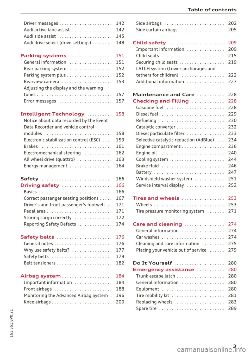
Audi active lane assist . . . . . . . . . . . . . . . . 142
Audi side assist . . . . . . . . . . . . . . . . . . . . . 145
Audi drive select (drive settings) . . . . . . . . 148
Parking systems
General information ............ .... .
Rear parking system .......... .. .... .
Parking system plus ...... ... .. .. .. .. . 151
151
152
152
Rearview camera . . . . . . . . . . . . . . . . . . . . 153
Adjusting the display and the warning
tones. . . . . . . . . . . . . . . . . . . . . . . . . . . . . . 157
Error messages . . . . . . . . . . . . . . . . . . . . . 157
Intelligent Technology . . . . . . . . . . 158
Notice about data recorded by the Event
Data Recorder and vehicle control
modules . . . . . . . . . . . . . . . . . . . . . . . . . . . 158
Electronic stabilization control (E5C) . . . . 159
Brakes . . . . . . . . . . . . . . . . . . . . . . . . . . . . . 161
Electromechanical steering . . . . . . . . . . . . 162
All wheel drive (quattro) . . . . . . . . . . . . . . 163
Energy management 164
Safety ... . .. .. ............. .. .. .. . 166
Driving safety . . . . . . . . . . . . . . . . . . . . 166
Basics . . . . . . . . . . . . . . . . . . . . . . . . . . . . . 166
Correct passenger seating positions . . . . . 167
Driver's and front passenger's footwell . . 171
Pedal area . . . . . . . . . . . . . . . . . . . . . . . . . . 171
Storing cargo correctly . . . . . . . . . . . . . . . 172
Reporting Safety Defects . . . . . . . . . . . . . . 17 4
Safety belts . . . . . . . . . . . . . . . . . . . . . . 176
General notes . . . . . . . . . . . . . . . . . . . . . . . 176
Why use safety belts? . . . . . . . . . . . . . . . . 177
Safety belts . . . . . . . . . . . . . . . . . . . . . . . . 179
Belt tensioners . . . . . . . . . . . . . . . . . . . . . . 182
Airbag system . . . . . . . . . . . . . . . . . . . . 184
Important information . . . . . . . . . . . . . . . 184
Front airbags . . . . . . . . . . . . . . . . . . . . . . . 188
Monitoring the Advanced Airbag System . 196
Knee airbags . . . . . . . . . . . . . . . . . . . . . . . . 200
Table of contents
Side airbags . . . . . . . . . . . . . . . . . . . . . . . . 202
Side curtain airbags . . . . . . . . . . . . . . . . . . 205
Child safety . . . . . . . . . . . . . . . . . . . . . . 209
Important information . . . . . . . . . . . . . . . 209
Child seats . . . . . . . . . . . . . . . . . . . . . . . . . 215
Securing child seats. ............... .. 219
LATCH system (Lower anchorages and
tethers for children) . . . . . . . . . . . . . . . . . 222
Additional information . . . . . . . . . . . . . . . 227
Maintenance and Care . . . . . . . . . . . 228
Checking and Filling . . . . . . . . . . . . . 228
Gasoline fuel . . . . . . . . . . . . . . . . . . . . . . . 228
Diesel fuel . . . . . . . . . . . . . . . . . . . . . . . . . 229
Refueling . . . . . . . . . . . . . . . . . . . . . . . . . . 230
Catalytic converter . . . . . . . . . . . . . . . . . . . 232
Diesel particulate filter . . . . . . . . . . . . . . . 233
Selective catalytic reduction (AdBlue) . . . 234
Engine compartment . . . . . . . . . . . . . . . . . 236
Engine oil . . . . . . . . . . . . . . . . . . . . . . . . . . 240
Cooling system . . . . . . . . . . . . . . . . . . . . . . 244
Brake fluid . . . . . . . . . . . . . . . . . . . . . . . . . 246
Battery . . . . . . . . . . . . . . . . . . . . . . . . . . . . 247
Windshield washer system . . . . . . . . . . . . 251
Service interval display 252
Tires and wheels . . . . . . . . . . . . . . . . . 253
Wheels ... .. .. .. .. ... ... .... ..... .. 253
T ire pressure monitoring system 271
Care and cleaning ......... ... .. .. 274
General information . . . . . . . . . . . . . . . . . 274
Car washes . . . . . . . . . . . . . . . . . . . . . . . . . 2 7 4
Cleaning and care information . . . . . . . . . 275
Placing your vehicle out of service . . . . . . 279
Do It Yourself . . . . . . . . . . . . . . . . . . . . 280
Emergency a ssistance . . . . . . . . . . . 280
Trunk escape latch . . . . . . . . . . . . . . . . . . . 280
Genera l information . . . . . . . . . . . . . . . . . 280
Equipment . . . . . . . . . . . . . . . . . . . . . . . . . 280
Tire mobility kit . . . . . . . . . . . . . . . . . . . . . 281
Replacing wheels . . . . . . . . . . . . . . . . . . . . 283
Spare tire . . . . . . . . . . . . . . . . . . . . . . . . . . 289
3
Page 11 of 328
,....,
N
0 > co ,....,
@
®
©
®
®
(J)
®
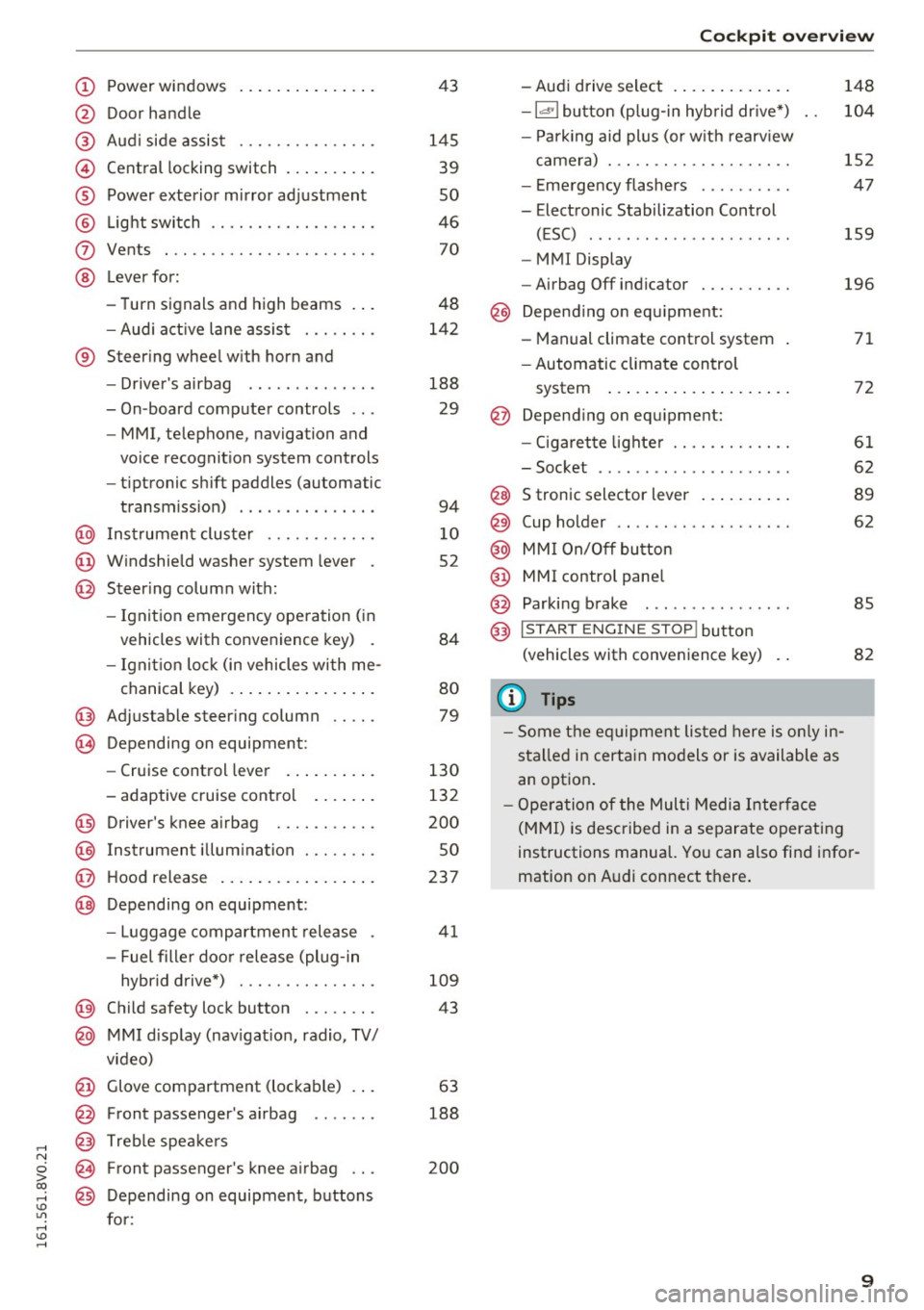
Power windows
Door handle
Aud i side assist ............ .. .
Central locking switch .. ... .. .. .
Power exterior mirror ad justment
L ig ht swit ch ............... .. .
Vents
L ever fo r:
- Turn signals and high beams . . .
- Audi a ct ive lane assis t ..... .. .
® Steer ing whee l w ith horn and
- Drive r's airbag ...... ..... .. .
- On-board compute r controls .. .
- MMI, telephone, navigation and
vo ice recognit ion system cont rols
- tiptronic sh ift paddles (automatic
transm iss ion) . .. .... ... .. .. .
@ Ins trumen t cluste r ....... .. .. .
@ W indshield washer system lever .
@ Steering column with:
- Ignit ion emergency operation ( in
vehicles with convenience key) .
- Ignit io n lock (in vehicles wi th me -
chanical key) . .. ..... ... .. .. .
@ Adjustable steer ing column .. .. .
(B) D epending on equipment:
- Cruise control leve r ..... .. .. .
- adaptive cruise contro l .. .. .. .
@ Driver's knee a irbag ........ .. .
@ Ins trumen t illum ination ..... .. .
@ Hood release ... .. .... ... .. .. .
@ Depending on equipment: 43
145 39
so
46 70
48
142
188 29
94
1 0
52
84
80
79
130
132
200
so
237
- Luggage compartment release . 41
- Fuel fille r doo r release (plug-in
hybrid drive*) . . . . . . . . . . . . . . . 109
@ Child safety lock button . . . . . . . . 43
@ MMI d isp lay (nav igat ion, radio, TV/
v ideo)
@ Glove compartment (lockable) . . . 63
@ Front passenger 's airbag . . . . . . . 188
@ Treb le spe akers
@ Front passenger's knee a irbag . . . 200
@ Depending on equipment, b uttons
for:
Coc kpit o ve rv iew
- Aud i drive select . .. .. ..... .. .
- la •I bu tton (p lug-in hyb rid dr ive *)
- P ark ing aid plus (or w it h rearv iew
came ra) . .. .. .............. .
- E me rgency flashers ......... .
- Electronic Stabilization Control (ESC) ....... .. ............ .
- MMI Display
- Airbag Off indicator ......... .
@ Depend ing o n eq uipment:
- Manual climate control system
- Automatic climate con trol
system ..... .. ... .. ..... .. .
@ Depend ing o n equ ipment:
- Ciga ret te lighte r ............ .
- Soc ket .. .. .. .. ............ .
@ S tronic selector lever .. ..... .. .
@) Cup holder .. .. .. ............ .
@ MM I On/Off bu tton
@ MMI contro l pane l
@ Parking brake . .. ............ .
@ I STAR T ENGINE ST OP ! button
(vehicle s with conve nience key)
(1) Tips
- Some t he e quipment listed here is o nly in
sta lled in certai n mo del s or is available as
an opt ion . 148
10
4
152
47
159
196
71
72
61
62
8 9
62
85
82
- Ope ra tio n of the Mul ti M edia Inte rface
(M MI) is described in a separate operatin g
instructions manual. Yo u can also fi nd info r
mation on A udi connect t here .
9
Page 12 of 328
Instrumen ts and ind icator ligh ts
Instruments and indicator Lights
Instruments
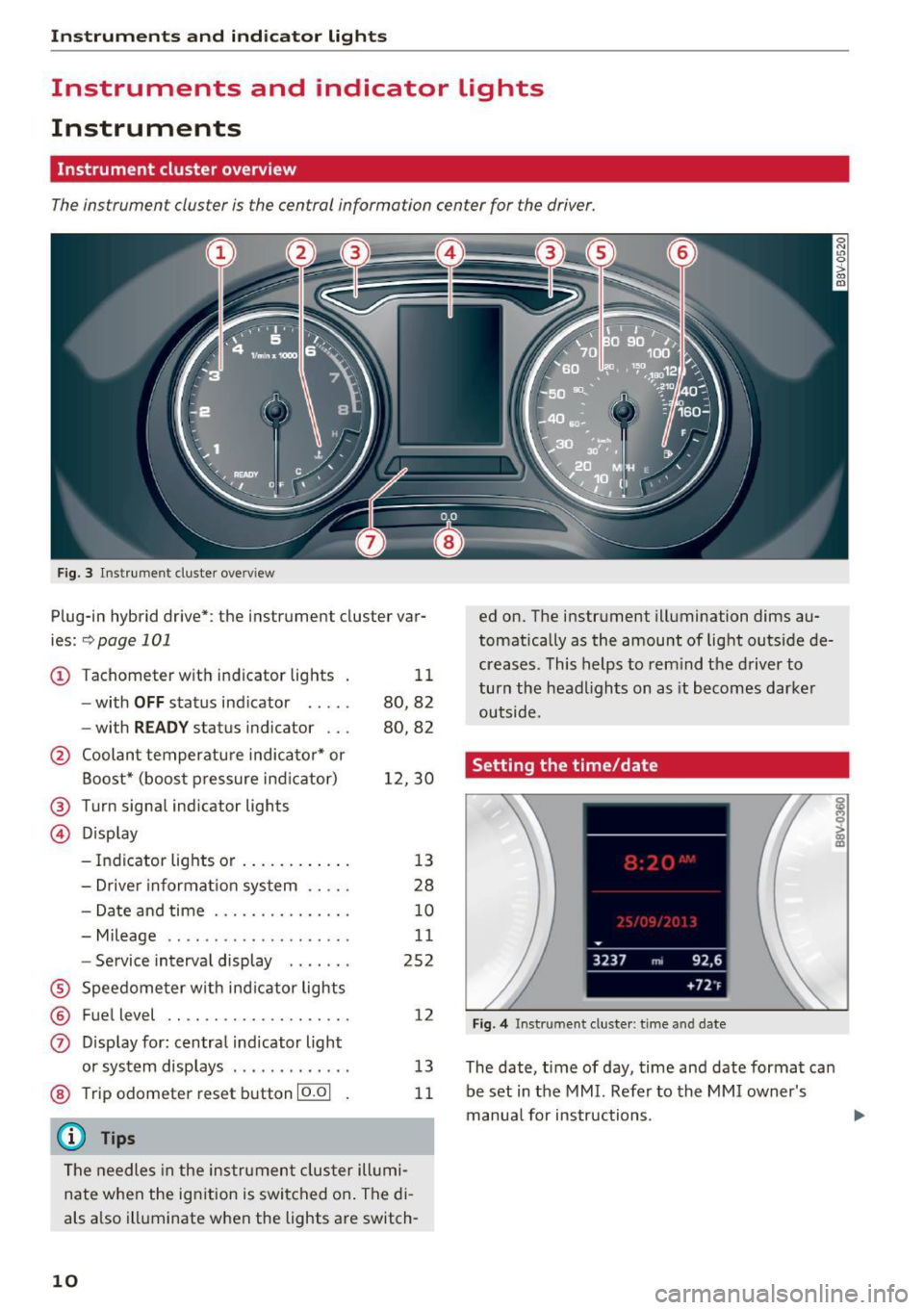
Instrument cluster overview
The instrument cluster is the central information center for the driver.
Fig. 3 Instrument cluster overv iew
Plug-in hybrid drive*: the instrument cluster var
ies:
~ page 101
CD Tachometer with indicator lights
- with
OFF status ind icator .... .
- with
READ Y status indicator .. .
@ Coolant temperatu re indicato r* or
Boost* (boost pressure ind icator)
@ Turn signal indicator lights
@ Display 11
80,82
80,82
1 2,30
- Indicator lights or . . . . . . . . . . . . 13
- Drive r informat ion system . . . . . 28
- Date and time . . . . . . . . . . . . . . . 10
- Mileage . . . . . . . . . . . . . . . . . . . . 11
- Service interva l display . . . . . . . 252
® Speedome ter w ith ind icator lights
® Fuel level ...... ........... .. .
0 D isp lay for : centra l indicator light
or system displays ............ .
@ Trip odometer reset button 10.01
{D) Tips
12
13
11
The needles in the instrume nt cluster ill umi
nate when the ign ition is swi tched o n. The di
als a lso illuminate when the lights are switch-
10
ed on. The instrument illumination dims au
tomatica lly as the amount of light outside de
creases. This helps to rem ind t he driver to
turn the head lights on as it becomes dar ker
outside.
Setting the time/date
Fig. 4 Instrument cluster : time and date
The date, time of day, time and date format can
be set in the MMI. Refer to the MMI owner's
manua l for instructions.
i 0 > a) m
Page 13 of 328
.... N
0 > CX)
.... I.Cl U"I
.... I.Cl ....
@ Tips
-When you switch the ignition off or open
the driver's door, the date and t ime are dis
played for approximately 30 seconds.
- You can also turn on the disp lay with the
10.01 button when the ignition is switched
off
q page 10 , fig. 3.
Tachometer
The tachometer displays the engine speed in rev
olutions per minute (RP/11).
The beginning of the red zone in the tachometer
indicates the maximum permitted engine speed
for all gears once the engine has been broken in
and when it is warm. You should select the "D/
S" (Drive) selector lever position or take your foot
off the accelerator pedal before reaching this
area .
It is best to avoid high engine speeds, even when
driving in tiptronic mode
q page 94 .
Vehicles with plug-in hybrid drive* have a power
meter instead of a tachometer. A digital tachom
eter can be displayed in the driver information
system
q page 29.
(D Note
The needle in the tachometer(I) c::;,page 10,
fig . 3
may only be in the red area of the gauge
for a short time or there is a r isk of damaging
the engine.
@ For the sake of the environment
Upshifting early helps you to save fuel and re
duce operating noise.
Instruments and indicator lights
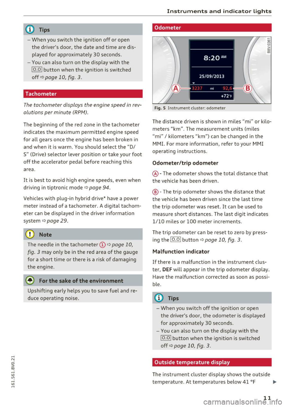
Odometer
Fig. 5 In st ru me nt cluster : odometer
The distance driven is shown in miles "mi" or kilo
meters "km" . The measurement units (miles
''mi"
I kilometers "km") can be changed in the
MMI. For more information, refer to your MMI
operating instructions .
Odometer/trip odometer
@-The odometer shows the total distance that
the vehicle has been driven .
®-The trip odometer shows the distance that
the vehicle has been driven since the last time
the tr ip odometer was reset . It can be used to
measure short distances. The last digit indicates
1/ 10 m iles or 100 meter increments.
The trip odometer can be reset to zero by press ing the
10.01 button c::;, page 10, fig. 3.
Malfunction indicator
If there is a malfunction in the instrument clus
ter,
DEF will appear in the trip odometer display.
Have the malfunction corrected as soon as possi
ble.
(D Tips
- When you switch off the ignition or open
the driver's door, the odometer is displayed
for approximately 30 seconds.
- You can also turn on the display with the
j o.o j button when the ignition is switched
off
q page 10, fig. 3 .
Outside temperature display
The instrument cluster display shows the outside
temperature . At temperatures below 41 °F ..,_
11
Page 14 of 328
Instruments and indicator lights
(+S °C), a snowflake symbol appears in front of
the temperature display.
If your vehicle is stationary or if you are driving at
very low speeds, the temperature displayed may
be slightly higher than the actual temperature
outside due to the heat radiating from the en
gine.
A WARNING
Do not assume the roads are free of ice based
on the outside temperature display . Be aware
that there may be ice on roads even when the
outside temperature is around 41 °F (+S
0
()
and that ice can increase the risk of accidents .
@ Tips
You can change the measurement units, for
example for temperature or speed, in the
MMI.
Fuel level
The display @ q page 10, fig. 3 only works when
the ignition is switched on. When the display has reached the reserve mark, the bottom LED will
turn red and the
tj] indicator light turns on
q page 24. Th e bottom LED blinks red when
the fuel level is very low.
The on-board computer shows the range based
on the fuel level~
page 29, On-board comput
er display.
For the tank capacity in your vehicle , refer to the
Technical Data
qpoge 303.
(D Note
Never drive until the tank is completely emp
ty . The irregular supply of fuel that results
from that can cause engine misfires . Uncom
busted fuel will then enter the exhaust sys
tem. This can cause overheating and damage
to the catalytic converter.
Coolant temperature indicator
In vehicles without a coolant temperature indica
t or, an indicator light . will turn on when the
12
coolant temperature is too high q page 20. Re
fer to
q 0 .
The coolant temperature indicator @ q page 10,
fig. 3
only works when the ignition is switched
on. To prevent engine damage, please observe
the following notes about the temperature rang
es .
Cold range
If only the LEDs at the bottom of the gauge turn
on, the engine has not reached operating tem
perature yet. Avoid high engine speeds, full ac
ce lerating and heavy engine loads.
Normal range
The engine has reached its operating tempera
ture once the LEDs up to the center of the gauge
turn on under normal driving conditions. The
LEDs higher up may turn on if the engine is under
heavy load or the outside temperature is high.
T his is no cause for concern as long as the. in
dicator light in the instrument cluster does not
turn on.
Hot range
If the LEDs in the upper area of the display and
the . indicator light in the instrument cluster
display turn on, the coolant temperature is too
high
q page 20 .
A WARNING
-Never open the hood if you can see or hear
steam or coolant escaping from the engine
compartment . This increases the risk of
burns . Wait until you no longer see or hear
steam or coolant escaping.
- The engine compartment in any vehicle can
be a dangerous area. Stop the engine and
allow it to cool before working in the engine
compartment. Always follow the informa
tion found in¢
page 236, Working in the
engine comportment.
([) Note
-In vehicles with a boost pressure indicator*,
this indicator replaces the temperature dis
play. To promote a long engine service life,
avoiding high engine speeds, full
Page 15 of 328
.... N
0 > CX)
.... I.Cl U"I
.... I.Cl ....
acceleration and heavy engine loads during
approximately the first 15 minutes when
the engine is cold is recommended. The
amount of time until the engine is warm de
pends on the outside temperature. Check
the engine oil temperature* if necessary
¢ page 32.
-Auxiliary headlights and other accessories in
front of the cooling-air intake impair the
cooling effect of the coolant . This increases
the risk of the engine overheating during
high outside temperatures and heavy en
gine load.
- The front spoiler also he lps to distr ibute
cooling air correct ly wh ile driving. If the
spo iler is damaged, the cooling effect will
be impaired and the risk of the engine over
heating will increase. See an authorized
Audi dealer or authorized Audi Service Fa
cility for assistance.
@ Tips
Diesel engines: due to the high efficiency of
these engines, the engine may not always
reach operating temperature in cold outside
temperatures. This is normal and not a cause
for concern.
Indicator lights
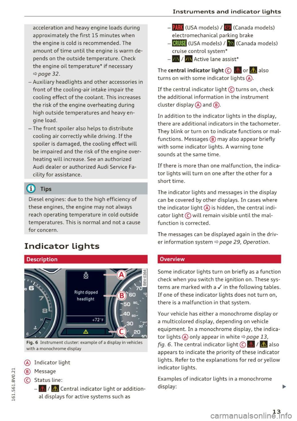
Description
Fig. 6 Instrument cl uster : example of a d isplay in veh icles
wit h a mo nochrome d isplay
@
®
©
Indicator light
Message
Status line:
- • Im, Central indicator light or addition
al displays for active systems such as
Instruments and indicator lights
-- (USA models)/ . (Canada models)
electromechanical parking brake
-18;(1 )~1~ (USA mode ls)/ . (Canada models)
cruise control system*
-•III Act ive lane assist*
The
central ind icator light© • or h also
turns on with some indicator lights @.
If the central indicator light © turns on, check
the additional information in the instrument
cluster display @ and @.
In addition to the indicator lights in the display,
there are addit ional ind icators in the tachometer .
They blink or turn on to indicate functions or mal
functions . Messages @ may also appear briefly
with some indicator lights. A warning tone
sounds at the same time.
If there is more than one malfunction, the indica
tor lights will turn on one after the other for a short time.
The ind icator lights and messages in the display
can be covered by other d isplays . In cases where
the indicator light @ is hidden, the central ind i
cator light © will remain visib le until the mal
function is corrected.
The messages can be displayed aga in in the driv
er information system
¢ page 29, Operation .
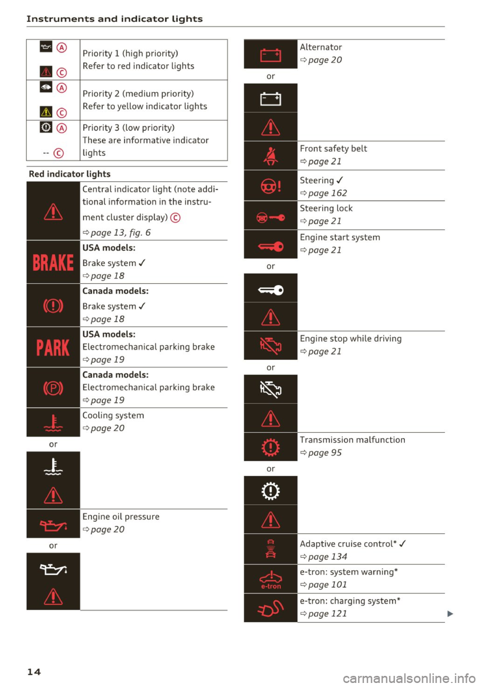
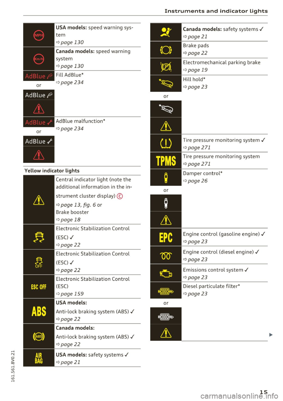
Overview
Some indicator lights turn on briefly as a funct ion
check when you sw itch the ignition on. These sys
tems are marked with a./ in the following tab les.
If one of these ind icator lights does not turn on,
there is a malfunction in that system .
Your vehicle has either a monochrome display or
a multicolored disp lay, depending on vehicle
equipment. In a monochrome display, the indica
tor lights @only appear in white ¢
page 13,
fig. 6. The central indicator light@• / rAi also
appears to indicate the priority of these indicator
lights. Refer to the explanations for red or yellow
indicator lights .
Examples of indicator lights in a monochrome
display :
13
Page 16 of 328
Instruments and indicator lights
IJ® Priority 1 (h igh prior ity)
. © Refer to red indicator
lights
m@ Pr ior ity 2 (medium priority)
II ©
Refer to yellow indicator lights
fm ® Priority 3 (low prio rity)
These are informative ind icator
-- © lights
Red indicator lights
,---=---------~--~:--
Central indicator light (note addi-
or
or
14
tional informat io n in the instru-
ment cluster display) ©
¢ page 13, fig. 6
Brake system ./
¢page 18
Canada models:
Brake system./
¢page 18
USA models:
Electromechanical parking brake
¢page 19
Canada models:
Electromechanical parking brake
¢page 19
Cooling system
¢page20
Engine oil pressure
¢page20
or
or
or
or Alternato
r
¢page20
Front safety be lt
¢ page 21
Steering./
¢page 162
Steering lock
¢page 21
Engine start system
¢page 21
Engine stop wh ile driving
¢ page 21
Transmission malfunction
¢page 95
Adaptive cruise contro l*./
¢page 134
e-tron: system warning*
¢page 101
e-tron: charging system*
¢page 121
Page 17 of 328
,....,
N
0 > co ,....,
or
USA models: speed war ning sys
tem
c;,page 130
Canada models : speed warning
sys tem
c;, page 130
Fill Ad Bl ue*
c;, page234
AdBlue ma lf u nction*
¢ page234
Yellow indicator lights
--------------Cent ral indi cato r light (note the
a d dit io nal info rm ation in the in-
strument cluster display) ©
¢page 13, fig. 6 or
B rak e boos te r
c;,page 18
Elect ronic Stabiliz ation Con trol
(ESC) ./
¢page22
Elect ronic Stabilization Control
(ESC) ./
c;, page22
Elec tronic Stabilization Con trol
( E SC)
c;, page 159
USA models:
Anti -loc k bra king system (A BS) ./
c;,page22
Canada models:
Anti-lock brak ing system (ABS) ./
¢page 22
USA models: safety systems ./
c;,page 21
Instruments and ind icator lights
or
·~
Lh
CD
TPMS
;
or
or
Canada models: safety systems ./
c;,page 21
Brake pads
c;, page22
Electromechanical parking brake
¢ page 19
Hill hold*
¢ page 23
Tire pressure mo nitoring system./
¢ page 271
Tire p ressure mo nitor ing system
¢ page 271
Dampe r contro l*
¢page 26
Engine co ntro l (gasoline engine)./
c;, page 23
Engine co ntro l (diese l engi ne) ./
c;,page 23
Emissions control system ./
¢page 23
Diesel pa rtic ulate fi lter*
¢ page 23
15
Page 26 of 328

Instruments and indicator lights
(D Tips
For additional information on the diesel par
ticulate filter, refer to¢
page 233.
!?) Engine speed limitation
A pp lies to ve hicles : w ith e ngin e spee d limit ation
[II Max. engine speed: XXXX rpm
The engine speed is automatically limited to the
speed displayed in the driver information system.
This protects the engine from overheating.
The engine speed limitation deactivates once the
engine is no longer in the critical temperature
range and you have released the accelerator ped
al once.
If the engine speed limitation was activated by
an engine control malfunction, the
[m indicator
light also turns on. Make sure the engine speed
does not go above the speed displayed, for exam
ple when downshifting. Drive to an authorized
Audi dealer or authorized Audi Service Facility im
mediately to have the malfunction corrected.
~ Engine oil level (min .)
II Check oil level
You may continue driving for the time being.
Check the engine oil level as soon as possible
¢page 240.
-If the engine oil level is too low, add engine oil
qpage242.
- If the engine oil level is correct and the indica
tor light still turns on, drive at low engine
speed to an authorized Audi dealer or author
ized Audi Service Facility.
'1::7' .., Engine oil sensor
• Oil level sensor: system fault!
The sensor to check the engine oil level has
failed. Drive to an authorized Audi dealer or au
thorized Audi Service Facility immediately to have
the malfunction corrected.
Ill Oil level sens.: oil change necessary. Please
contact Service
24
The engine oil level is too high.
Drive to an authorized Audi dealer or authorized
Audi Service Facility immediately to have the
malfunction corrected .
(D Note
Refer to the description in the Owner's Man
ual
q page 242, Checking the engine oil level
and ¢ page 242, Adding engine oil
ID Please refuel
If the indicator light turns first turns on and this
message appears, the tank contains the follow
ing amount of fuel:
- Front wheel drive: approximately 1.8 gallons (7
liters)
-All wheel drive: approximately
2.2 gallons (8.5
liters)
fiD Please refuel immediately
If the indicator light turns on the message ap
pears, the fuel tank is almost empty. Refuel the
vehicle immediately.
ID Fuel tank malfunction! Please contact Serv
ice
If the indicator light turns on and the message
appears:
- there is a malfunction in the fuel tank system,
or
- in vehicles with diesel engines, water may have
collected in the fuel filter.
Drive to an authorized Audi dealer or authorized
Audi Service Facility immediately to have the
malfunction corrected.
Page 30 of 328
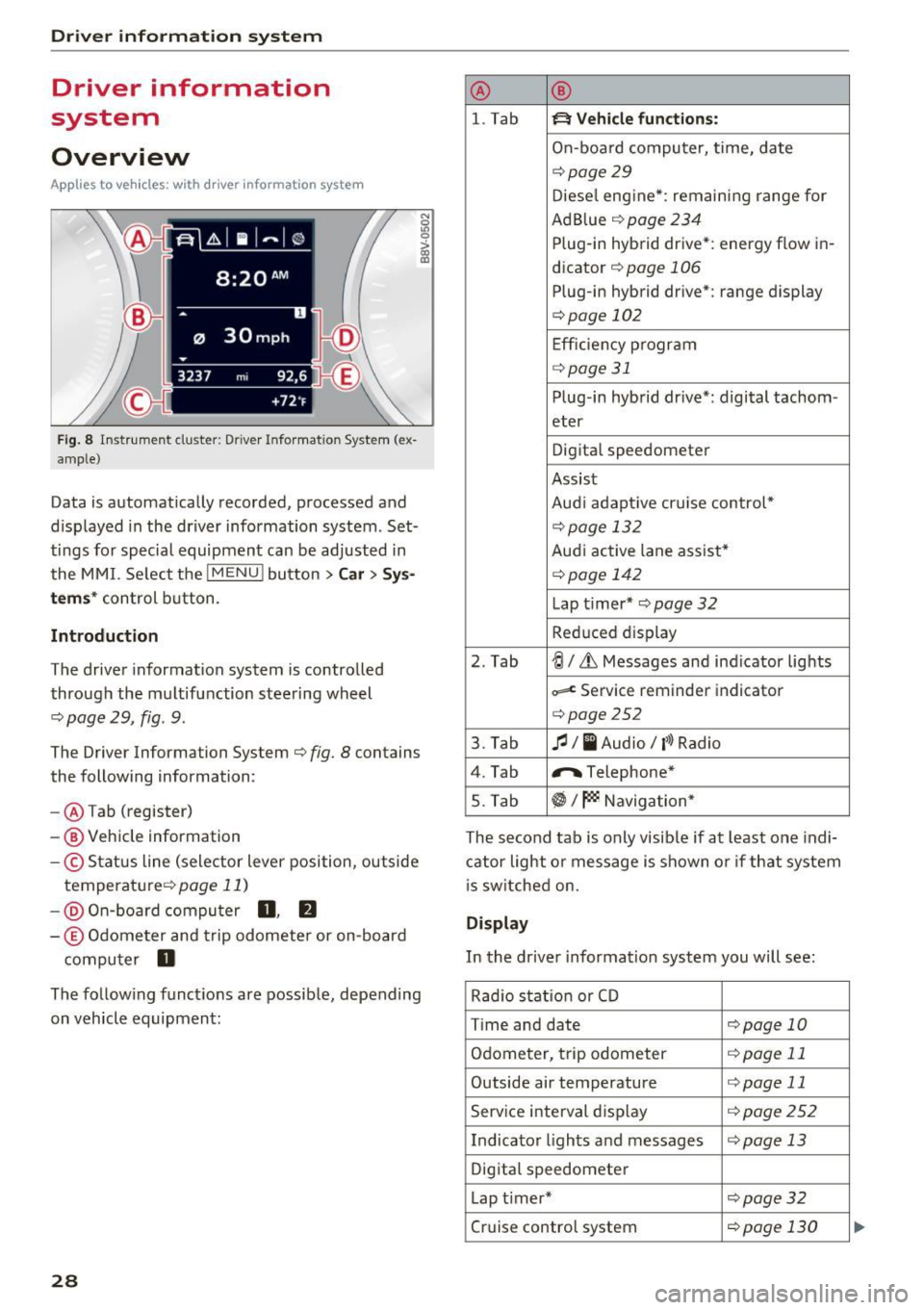
Driver information system
Driver information
system
Overview
A pp lies to veh icles: w ith driver information system
F ig. 8 In strum ent cluster: Drive r Info rmation System (ex
amp le)
Data is automatically recorded, processed and
d isplayed in the driver information system . Set
tings for special equipment can be adjusted in
the MMI. Se lect the
I MENU ! button >Car > Sys
tems* control button .
Introduction
The driver inform ation system is controlled
through the multifunction steering wheel
<=.> page 29, fig . 9.
The Driver Information System <=.> fig. 8 contains
the following information:
- @ Tab (register)
- @ Vehicle information
-© Status line (selector lever position, outside
temperature <=.>
page 11)
-@ On-board computer 0, fJ
-© Odometer and trip odometer or on-board
computer
D
N
0
LO 0
> OJ a,
The follow ing functions are possible, depending
on vehicle equipment:
28
@ ®
l. Tab ~ Vehicle functions:
On-board computer, time, date
<=.>page 29
Diesel engine*: remaining range for
Ad Blue <=.>
page 234
Plug-in hybrid drive*: energy flow in-
dicator
<=.> page 106
Plug-in hybrid drive*: range display
<=.>page 102
Efficiency program
<=.>page 31
Plug-in hybrid drive*: digital tachom -
eter
Digital speedometer
Assist
Aud i adapt ive cruise control*
<=.> page 13 2
Audi active lane assist*
<=.> page 142
Lap t i mer* <=.> page 32
Reduc ed display
2. Tab
~I&, Messages and ind icator lights
~ Service reminder indicator
<=.>page252
3. Tab fl I I Audio/ l'>l Radio
4. Tab "'Telephone*
5. Tab
~I~ Navigation*
The second tab is only visib le if at least one indi
cator light or message is shown or if that system
is switched on.
Display
In the driver information system you will see :
Rad io stat ion or CD
T ime and date
<=.>page 10
Odometer, trip odometer <=.>page 11
Outside air temperature <=.>page 11
Service interval display <=.>page 252
Indicator lights and messages <=.>page 13
Digital speedometer
Lap timer*
<=.>page 32
Cruise control system <=.>page 130