fog light AUDI A3 2020 Owner´s Manual
[x] Cancel search | Manufacturer: AUDI, Model Year: 2020, Model line: A3, Model: AUDI A3 2020Pages: 400, PDF Size: 107.47 MB
Page 45 of 400
8V2012721BK
Lights and Vision
Lights and Vision
Exterior lighting
Stare MUL Las eal
B8V-0430
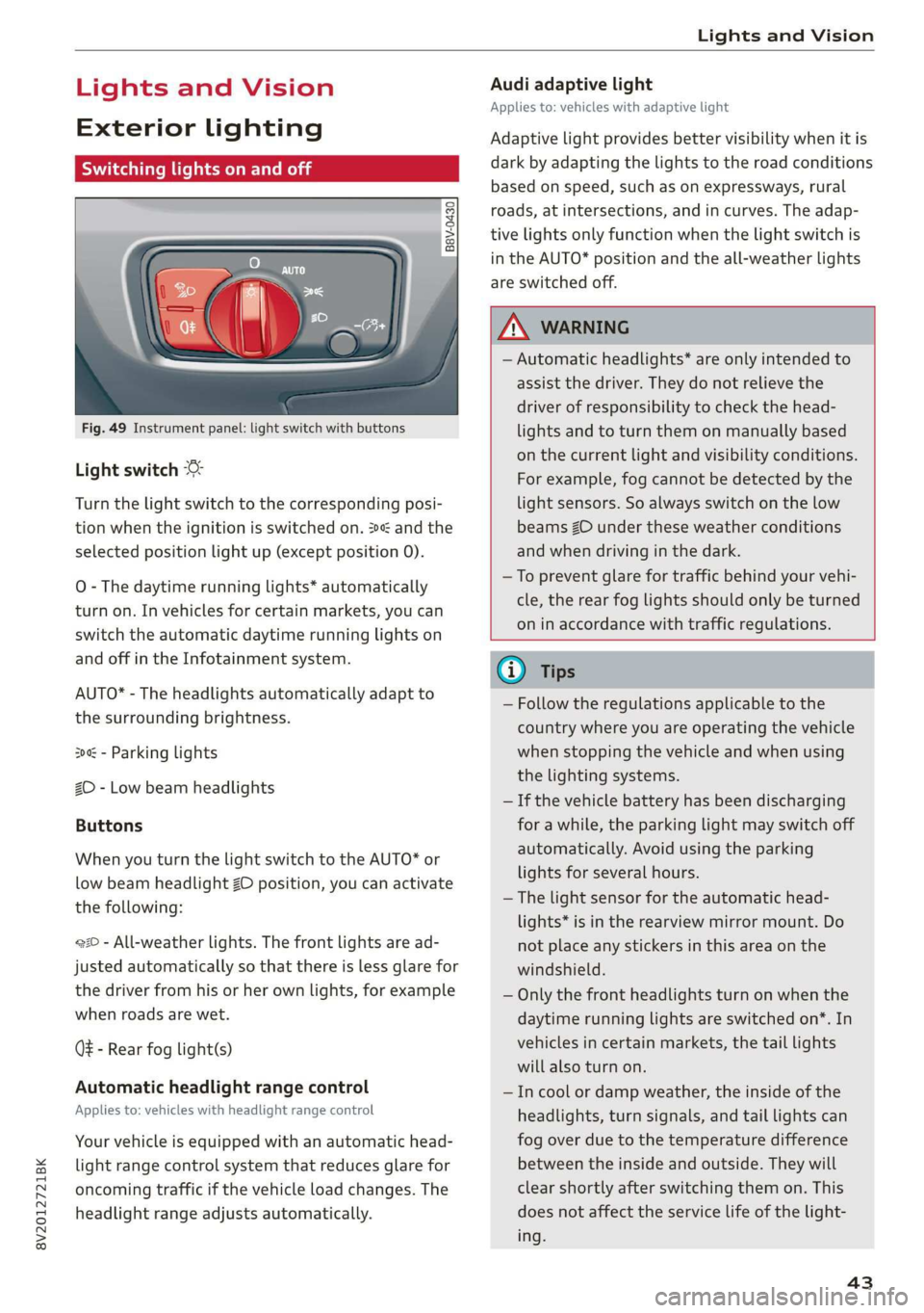
Fig. 49 Instrument panel: light switch with buttons
Light switch
Turn the light switch to the corresponding posi-
tion when the ignition is switched on. 2 and the
selected position light up (except position 0).
O
- The daytime running lights* automatically
turn on. In vehicles for certain markets, you can
switch the automatic daytime running lights on
and off in the Infotainment system.
AUTO* - The headlights automatically adapt to
the surrounding brightness.
300 - Parking lights
2D - Low beam headlights
Buttons
When you turn the light switch to the AUTO* or
low beam headlight ZO position, you can activate
the following:
220 - All-weather lights. The front lights are ad-
justed automatically so that there is less glare for
the driver from his or her own lights, for example
when roads are wet.
Q - Rear fog light(s)
Automatic headlight range control
Applies to: vehicles with headlight range control
Your vehicle is equipped with an automatic head-
light range control system that reduces glare for
oncoming traffic if the vehicle load changes. The
headlight range adjusts automatically.
Audi adaptive light
Applies to: vehicles with adaptive light
Adaptive light provides better visibility when it is
dark by adapting the lights to the road conditions
based on speed, such as on expressways, rural
roads, at intersections, and in curves. The adap-
tive lights only function when the light switch is
in the AUTO* position and the all-weather lights
are switched off.
Z\ WARNING
— Automatic headlights* are only intended to
assist the driver. They do not relieve the
driver of responsibility to check the head-
lights and to turn them on manually based
on the current light and visibility conditions.
For example, fog cannot be detected by the
light sensors. So always switch on the low
beams ZO under these weather conditions
and when driving in the dark.
—To prevent glare for traffic behind your vehi-
cle, the rear fog lights should only be turned
on in accordance with traffic regulations.
G) Tips
— Follow the regulations applicable to the
country where you are operating the vehicle
when stopping the vehicle and when using
the lighting systems.
— If the vehicle battery has been discharging
for a while, the parking light may switch off
automatically. Avoid using the parking
lights for several hours.
— The light sensor for the automatic head-
lights* is in the rearview mirror mount. Do
not place any stickers in this area on the
windshield.
— Only the front headlights turn on when the
daytime running lights are switched on*. In
vehicles in certain markets, the tail lights
will also turn on.
—Incool or damp weather, the inside of the
headlights, turn signals, and tail lights can
fog
over due to the temperature difference
between the inside and outside. They will
clear shortly after switching them on. This
does not affect the service life of the light-
ing.
43
Page 47 of 400
8V2012721BK
Lights and Vision
manually depending on light and visibility
conditions. It may be necessary to operate
them manually in situations such as:
— In adverse weather conditions such as fog,
heavy rain, blowing snow or spraying water.
— On roads where oncoming traffic may be
partially obscured, such as expressways.
— If there are road users with poor lighting,
such as bicyclists.
— In tight curves and on steep hills.
—In poorly lit areas.
— With strong reflectors, such as signs.
— If the area of the windshield near the sensor
is fogged over, dirty, icy or covered with a
sticker.
Adjusting the exterior lighting
You can adjust the exterior lighting separately.
The settings depend on the vehicle equipment.
The functions are adjusted in the Infotainment
system.
> Select in the Infotainment system: [MENU] but-
ton > Vehicle > left control button > Vehicle
settings > Exterior lighting.
Automatic headlights
You can adjust the following settings in the Auto-
matic
headlights menu:
Activation time - You can adjust if the headlights
switch on Early, Medium or Late according to the
sensitivity of the light sensor.
Headlight assistant - You can switch the high
beam assistant* on and off.
Entry/exit lighting
When it is dark, the Entry/exit lighting illumi-
nates the area around the vehicle when unlocking
the vehicle and after switching off the ignition
and opening the driver's door.
The entry/exit lighting only works when it is dark
and the light switch is in the AUTO* position.
)_ This function is not available in all countries.
Daytime running lights!)
The daytime running lights can be turned on and
off. When daytime running lights are turned on,
the lights will stay on continuously whenever the
ignition is switched on.
Emergency flashers
B8V-0210
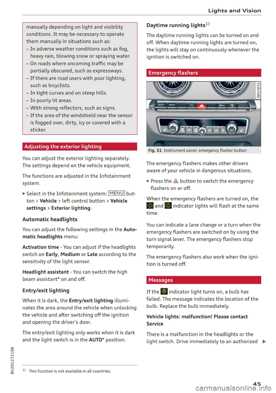
Fig. 51 Instrument panel: emergency flasher button
The emergency flashers makes other drivers
aware of your vehicle in dangerous situations.
> Press the A button to switch the emergency
flashers on or off.
When the emergency flashers are turned on, the
a and BY indicator lights will flash at the same
time.
You can indicate a lane change or a turn when the
emergency flashers are switched on by using the
turn signal lever. The emergency flashers stop
temporarily.
The emergency flashers also work when the igni-
tion is turned off.
If the ka indicator light turns on, a bulb has
failed. The message indicates the location of the
bulb. Replace the bulb immediately.
Vehicle lights: malfunction! Please contact
Service
There is a malfunction in the headlights or the
light switch. Drive immediately to an authorized >
45
Page 63 of 400

8V2012721BK
Stowing and using
braking maneuvers or in the event of an ac-
cident.
Loose objects can be thrown around the ve-
hicle interior during sudden driving or brak-
ing maneuvers, which increases the risk of
an accident. Always stow objects securely in
the luggage compartment and secure them
at the tie-downs. Use straps suitable for
heavy objects.
If pieces of luggage or objects are secured
to the tie-downs with unsuitable or dam-
aged straps, this can increase the risk of in-
jury during braking maneuvers or accidents.
When transporting heavy objects, the vehi-
cle characteristics will change due to the
shift in the center of gravity, which increases
the risk of an accident. You may need to
adapt your driving style and speed to the
current conditions.
The cargo net is only strong enough to se-
cure light objects. Heavy objects are not ade-
quately secured. Attempting to secure heavy
objects increases the risk of injury.
Never exceed the permitted axle and load
and vehicle weight > page 380.
Never secure a child safety seat to the tie-
downs.
Never leave your vehicle unattended, espe-
cially if the luggage compartment lid is
open. Children could enter the luggage com-
partment and close the luggage compart-
ment lid from the inside. This creates the
risk of fatal injury, since the children would
be locked in and may not be able to escape
by themselves.
Do not allow children to play in or on the ve-
hicle. Close and lock the luggage compart-
ment lid as well as all other doors when you
leave the vehicle.
Never transport passengers in the luggage
compartment. Every passenger must be cor-
rectly secured with the safety belts in the
vehicle > page 245.
Be careful when releasing the backrest and
folding
it forward. To reduce the risk of be-
ing pinched, pay attention and check when
folding backrests forward.
— The backrest must be securely latched so
objects cannot slide forward out of the lug-
gage compartment during sudden braking.
— The backrest must be latched securely to en-
sure that the safety belt is protecting the
center seating position.
— Always pull forward on the backrest to make
sure it is check if it is correctly locked in
place.
@) Note
—To reduce the risk of damage, move the rear
head restraints down > page 57 before fold-
ing the rear backrests forward.
— When folding the backrest forward, make
sure the outer safety belts are in the belt
guide recess so that they do not get pinched
in the backrest lock and damaged. Other ob-
jects should be removed from the rear
bench seat to protect the backrest from
damage.
— If you move the front seat back when the
rear seat backrest is folded forward, you
could damage the head restraints on the
rear seat.
— Make sure that the heating grid strips for
the rear window defogger are not damaged
by abrasive objects.
@ Tips
— The tire pressure must be adapted to the
load > page 330.
— You can purchase straps at specialty stores.
Luggage compartment cover
Applies to: vehicles with luggage compartment cover
5 = S$
= = &
oO
Fig. 74 Luggage compartment: luggage compartment cov-
er >
61
Page 68 of 400

Warm and cold
2-zone deluxe automatic climate control
Applies to: vehicles with 2-zone deluxe automatic climate control
B8V-0590
Fig. 82 2-zone deluxe automatic climate control: controls
The functions can be switched on and off by
pressing the buttons or adjusted by turning the
knob. The LED in a button will light up when the
function is switched on.
The deluxe climate control system automatically
maintains a temperature once it has been set. In
all heating mode functions except defrost, the
blower only switches to a higher speed once the
engine coolant has reached a certain tempera-
ture.
AUTO Automatic mode or eco mode*
Automatic mode maintains a constant tempera-
ture inside the vehicle. Air temperature, airflow
and air distribution are controlled automatically.
AUTO mode switches off once a button in the cli-
mate control system is pressed.
Applies to: vehicles with eco mode: Pressing the
AUTO button briefly when automatic mode is ac-
tive will activate the energy-saving mode of the
climate control system. eco will appear on the
control panel display. You can end eco mode by
pressing the AUTO button again.
A/C cooling mode
The cooling mode only functions with the blower
turned on. You can turn the cooling system on or
off by pressing the A/C button. The air is not
cooled and humidity is not removed when cooling
66
mode is switched off. This can cause fog on the
windows. The cooling mode switches off auto-
matically when there are cold outside tempera-
tures.
@ / @ Temperature
The temperature for the driver's and front pas-
senger's side can be adjusted separately with the
dials @/@). Temperatures between 60 °F
(+16 °C) and 84 °F (+28 °C) can be set. If outside
of this range, LO or HI will appear in the climate
control system display. In both settings, the cli-
mate control runs constantly at the maximum
cooling or heating level. The temperature is not
regulated.
Synchronization: Pressing and holding the AUTO
button for two seconds transfers the tempera-
ture setting for the driver to the front passeng-
er's side. This applies a temperature change to
the front passenger's side.
S8 Blower
Using the dial $8, you can manually adjust the
volume of air generated by the blower to your
preference. The blower should always run at a
low setting to prevent the windows from fogging
and to ensure a continuous exchange of air inside
the vehicle. To have the blower regulated auto-
matically, press the AUTO button.
Page 81 of 400

8V2012721BK
Driving
strength can depend on various factors, for ex-
ample:
— If you are in tiptronic mode > page 76. Or
—If the sport driving mode "S" was selected.
Plug-in hybrid drive modes
Applies to: vehicles with plug-in hybrid drive
Adjusting the plug-in-hybrid mode
The <8" button is located above the selector lever
in the center console.
> Press the <$" button repeatedly until the de-
sired mode is displayed in the instrument clus-
ter.
The active mode is displayed the first time the
Hybrid driving
If the <8Y button does not turn on, you are driv-
ing in hybrid mode. The vehicle can be driven
with the combustion engine or with the electric
motor if the conditions for it have been met
=> page 79, Conditions for electric driving.
© e-tron mode: Hybrid - The electric motor and
combustion engine are working efficiently to-
gether. Hybrid mode is particularly effective for
long trips.
* e-tron mode: Battery Hold - The vehicle is
driven predominantly with the combustion en-
gine to maintain the high-voltage battery charge
level for as long as possible.
Electric driving
can be driven by the electric motor if the condi-
tions for this have been met > page 79, Condi-
tions for electric driving.
Conditions for electric driving
— Driving program “S” must not be selected.
— The charge level of the high-voltage battery
must be sufficient.
— The temperature of the high-voltage battery
must be adequate (outside temperatures not
below approximately 14°F / -10°C and not
above approximately 104°F / 40°C).
— The driving speed must be under approximately
80 mph (130 km/h).
— The accelerator pedal must not be pressed too
hard.
Indicator lights
Symbol |Meaning
EV mode is switched on and active.
You are driving only with electric
power.
EV mode is not available, because
the conditions for electric driving
have not been met.
The combustion engine is running.
The hybrid mode e-tron mode: Bat-
tery Hold is active.
The hybrid mode e-tron mode: Hy-
brid is active.
G) Tips
— When temperatures are below approximate-
ly 14 °F (-10 °C), the vehicle heat output in
EV mode is reduced in order to attain higher
ranges. If the windows fog up or a higher
heat output is desired, switch on the Hybrid
or Battery Hold mode.
— Applies to: Battery Hold mode: The high-
voltage battery charge level can still de-
crease depending on the driving behavior.
—If you select the sport driving mode "S", the
Battery Hold mode is automatically select-
ed
@
— It may be necessary for the gasoline engine
to run longer for technical reasons, such as
when condensation accumulates in the en-
gine. Driving exclusively in electric mode is
not possible in this phase.
— Before driving downhill a long distance ona
steep hill, decrease your speed and select a
lower gear. When driving with a trailer, the
"S" selector lever position must be selected.
This makes use of the engine braking effect
and reduces the load placed on the brakes.
Tips
79
>
Page 117 of 400
8V2012721BK
Assist systems
Assist systems
Speed warning system
Applies to: vehicles with speed warning system
The speed warning system helps you to stay be-
low a specified maximum speed that can be set,
changed or deleted in the Infotainment system.
The speed warning system warns you if you are
exceeding the maximum speed that you have set.
A warning tone will sound as soon as your speed
exceeds the stored value slightly. The ow in-
dicator light will appear at the same time in the
instrument cluster display along with a message.
The fe) indicator light and the message turn
off if the speed falls back below the stored maxi-
mum speed.
Setting a threshold is recommended if you would
like to be reminded when you reach a certain
maximum speed. Situations where you may want
to do so include driving in a country with a gener-
al speed limit or if there is a specified maximum
speed for winter tires.
Setting the warning threshold
> Select in the Infotainment system: [MENU] but-
ton > Vehicle > left control button > Driver as-
sistance > Speed warning > Manual.
G) Tips
Regardless of the speed warning system, you
should always monitor your speed using the
speedometer and make sure you are following
the legal speed limit.
Messages
Applies to: vehicles with speed warning system
Manually set speed limit XX mph
(km/h) exceeded
The stored speed was exceeded.
Cruise control system
Applies to: vehicles with cruise control system
The cruise control system assists the driver in
maintaining a constant speed above approxi-
mately 15 mph (20 km/h). The system maintains
the desired speed by braking and accelerating.
ZA WARNING
— Always pay attention to the traffic around
your vehicle when the cruise control system
is in operation. As the driver, you are always
responsible for controlling your vehicle
speed and the distance between your vehicle
and
other vehicles.
— For safety reasons, cruise control should not
be used in the city, in stop-and-go traffic, on
winding roads, and when road conditions are
poor (such as ice, fog, gravel, heavy rain,
and conditions that could lead to hydroplan-
ing), because this increases the risk of an ac-
cident.
— Switch the cruise control off temporarily
when driving in turning lanes, highway exits,
or in construction zones.
—To reduce the risk of an accident, you should
only resume the stored speed if it is suitable
for the current traffic conditions.
@) Note
— Conventional drive system: before driving
downhill a long distance on a steep hill, de-
crease your speed and select a lower gear.
This makes use of the engine braking effect
and reduces the load placed on the brakes.
— Plug-in hybrid drive: before driving downhill
a long distance on a steep hill, decrease
your speed and use the recuperation braking
effect > page 78. This reduces the load on
the brakes.
(i) Tips
The brake lights turn on when the brakes are
applied automatically.
115
Page 131 of 400

8V2012721BK
Assist systems
signal. In this case, it assumes that you are
changing lanes intentionally.
Z\ WARNING
— The system warns the driver that the vehicle
is leaving the lane using corrective steering.
The driver is always responsible for keeping
the vehicle within the lane.
— The system can help you keep the vehicle in
the lane, but it does not drive by itself. Al-
ways keep your hands on the steering wheel.
— Corrective steering may not occur in certain
situations, such as during heavy braking.
— There may be cases where the camera does
not recognize all lane marker lines. Correc-
tive steering can only take place on the side
of the vehicle where lane marker lines are
detected.
— Other road structures or objects could possi-
bly be identified unintentionally as lane
marker lines. As a result, corrective steering
may be unexpected or may not occur.
— The camera view can be restricted, for exam-
ple by vehicles driving ahead or by rain,
snow, heavy spray light shining into the
camera or by dirt on the window. This can
result in active lane assist not detecting the
lane marker lines or detecting them incor-
rectly.
— Under certain conditions such as ruts in the
road, an inclined roadway or crosswinds, the
corrective steering alone may not be enough
to keep the vehicle in the middle of the lane.
— For safety reasons, active lane assist must
not be used when there are poor road and/or
weather conditions such as slippery roads,
fog, gravel, heavy rain, snow and the poten-
tial for hydroplaning. Using active lane as-
sist under these conditions may increase the
risk of a crash.
SY iicealiaremelilie Rela
Applies to: vehicles with Audi active lane assist
B4M-0064|
Fig. 121 Turn signal lever: switching Active lane assist on
and off (example)
B4M-0090
Fig. 122 Windshield: camera window for active lane assist
> Press the button to switch the system on and
off > fig. 121. The indicator light in the instru-
ment cluster turns on or off.
129
Page 348 of 400
Care and cleaning
ZA WARNING
— Never immerse the Audi e-tron charging sys-
tem and connectors in water.
— The Audi e-tron charging system must only
be cleaned when the control unit is com-
pletely disconnected from the power supply
and from the vehicle.
@) Note
— Headlights and tail lights
— Never clean headlights or tail lights with a
dry cloth or sponge.
— Do not use any cleaning products that con-
tain alcohol, because they could cause
cracks to form.
— Wheels
— Never use any paint polish or other abra-
sive materials.
— Damage to the protective layer on the
rims, such as stone chips or scratches,
must be repaired immediately.
— Camera lenses
— Never use warm or hot water to remove
snow or ice from the camera lens. This
could cause the lens to crack.
— Never use abrasive cleaning materials or
alcohol to clean the camera lens. This
could cause scratches and cracks.
— Power top
— Remove bird droppings immediately.
— Never use gasoline, spot remover, ben-
zene, paint thinner or other solvents to re-
move.
— Door windows
— Remove snow and ice on windows and ex-
terior mirrors with a plastic scraper. To re-
duce the risk of scratches, move the scra-
per only in one direction and not back and
forth.
— Never remove snow or ice from door win-
dows and mirrors using warm or hot water
because this could cause cracks to form.
—To reduce the risk of damage to the rear
window defogger, do not apply any stick-
ers on the heating wires on the inside of
the window.
346
— Decorative parts and trim
— Never use chrome care or cleaning prod-
ucts.
— Paint
— To reduce the risk of scratches, the vehicle
must be free of dirt and dust before pol-
ishing or waxing.
—To prevent paint damage, do not polish or
wax the vehicle in direct sunlight.
—To reduce the risk of paint damage, do not
polish away rust spots.
— Remove cosmetics and sunscreen immedi-
ately because they could damage the
paint.
— Decorative decals
—To reduce the risk of damage, do not use
any rough powder or abrasive cleaning
products.
—To reduce the risk of damage, do not pol-
ish decorative decals that have a matte or
printed finish.
— Due to the risk of damage, do not use an
ice scraper to remove snow and ice on win-
dows with decorative decals on them.
— Displays and instrument cluster
— The displays/instrument cluster and the
trim surrounding them must not be
cleaned with dry cleaning methods be-
cause they could be scratched.
— Make sure that the instrument cluster is
switched off and has cooled off before
cleaning it.
— Make sure no fluids enter the spaces be-
tween the instrument cluster and the
trim, because that could cause damage.
— Controls
— Make sure that no fluids enter the con-
trols, because this could cause damage.
— Safety belts
— Do not remove the safety belts to clean
them.
— Never clean safety belts or their compo-
nents with chemicals or with corrosive flu-
ids or solvents and never allow sharp ob-
jects to come into contact with the safety
belts. This could cause damage to the belt
webbing.
Page 363 of 400
8V2012721BK
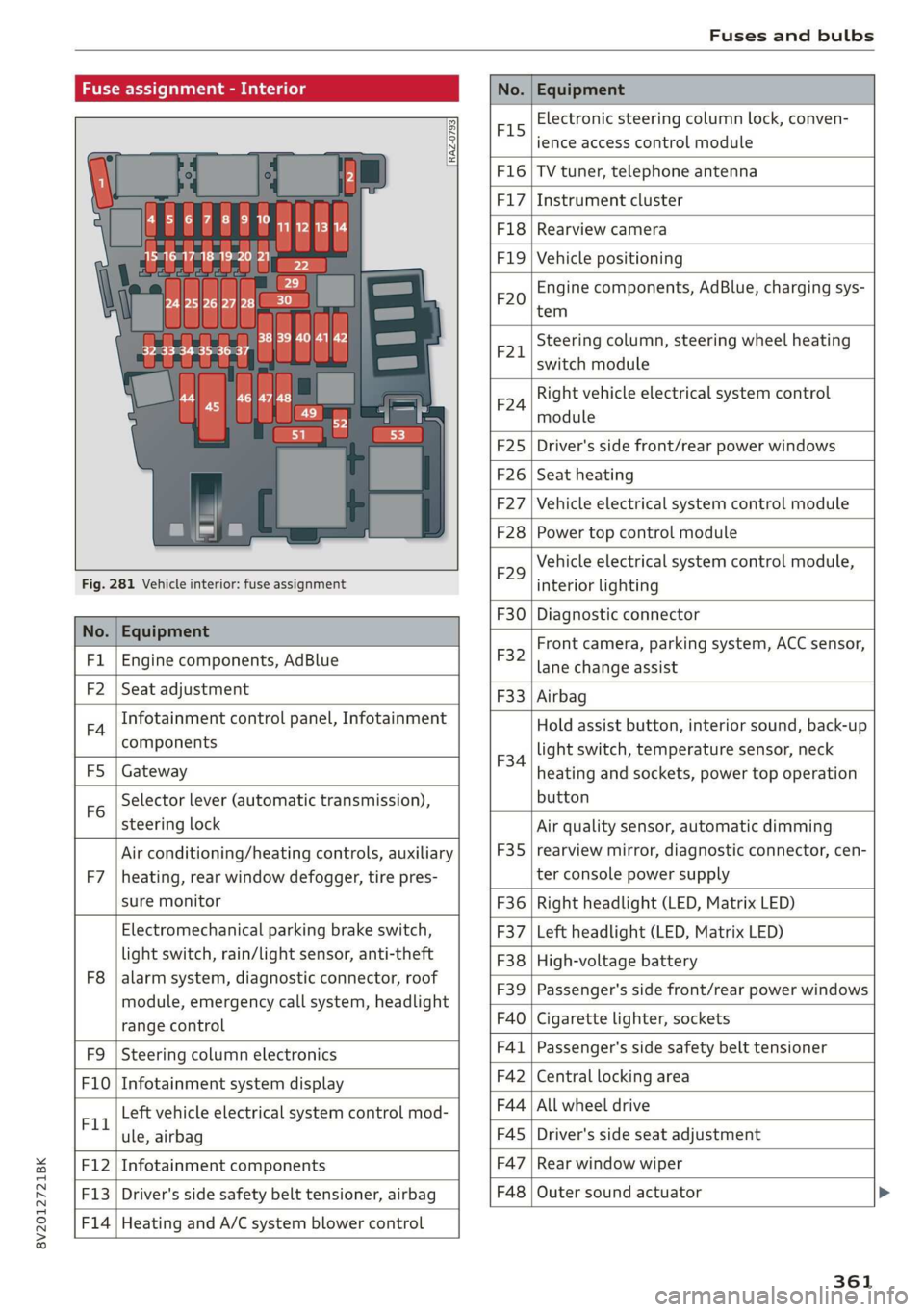
Fuses and bulbs
Fuse assignment - Interior
No. Equipment
RAZ-0793,
PO ee
15°16°17-18 19 20 21
PZ ply lip y ips}
ei Hes ole” So}
32°33 34 35 36 37
F15
Electronic steering column lock, conven-
ience access control module
F16 TV tuner, telephone antenna
F17 Instrument cluster
F18 Rearview camera
F1I9 Vehicle positioning
F20
Engine components, AdBlue, charging sys-
tem
F221
Steering column, steering wheel heating
switch module
F24
Right vehicle electrical system control
module
F25 Driver's side front/rear power windows
F26 Seat heating
F27 Vehicle electrical system control module
F28 Power top control module
Fig. 281 Vehicle interior: fuse assignment
F29
Vehicle electrical system control module,
interior lighting
No. Equipment
F30 Diagnostic connector
FL Engine components, AdBlue
F2 Seat adjustment
F32
Front camera, parking system, ACC sensor,
lane change assist
F4
Infotainment control panel, Infotainment
components
F33 Airbag
FS Gateway
Fo
Selector lever (automatic transmission),
steering lock
F34
Hold assist button, interior sound, back-up
light switch, temperature sensor, neck
heating and sockets, power top operation
button
Air conditioning/heating controls, auxiliary F35
Air quality sensor, automatic dimming
rearview mirror, diagnostic connector, cen-
F7 |heating, rear window defogger, tire pres- ter console power supply
sure monitor F36 | Right headlight (LED, Matrix LED)
Electromechanical parking brake switch, F37 | Left headlight (LED, Matrix LED)
light switch, rain/light sensor, anti-theft F38 | High-voltage battery
ae ene eee dent F39 | Passenger's side front/rear power windows
range control F40 | Cigarette lighter, sockets
F9 |Steering column electronics F41 | Passenger's side safety belt tensioner
F10 | Infotainment system display F42 | Central locking area
Tl Left vehicle electrical system control mod- F44 al ee
ule, airbag FAS | Driver's side seat adjustment
F12 | Infotainment components F47 | Rear window wiper
F13 | Driver's side safety belt tensioner, airbag F48 | Outer sound actuator
F14 | Heating and A/C system blower control
361
Page 364 of 400
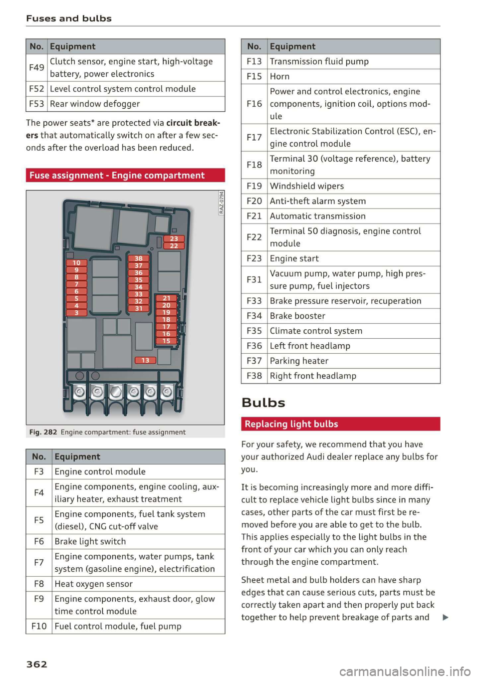
Fuses and bulbs
No. | Equipment No. | Equipment
Clutch sensor, engine start, high-voltage
F49 3
battery, power electronics
F52 F53 Level control system control module
Rear window defogger
The power seats* are protected via circuit break-
ers that automatically switch on after a few sec-
onds after the overload has been reduced.
Fuse assignment - Engine compartment
RAZ-0794)
1 0
&
F:}
vi
6
5
4
5}
Fig. 282 Engine compartment: fuse assignment
No. | Equipment
F3 | Engine control module
FA Engine components, engine cooling, aux-
iliary heater, exhaust treatment
Engine components, fuel tank system
(diesel), CNG cut-off valve
Brake light switch
E5
Fo
Engine components, water pumps, tank
F7 ; . ee cae
system (gasoline engine), electrification
F8
F9
Heat oxygen sensor
Engine components, exhaust door, glow
time control module
F10 | Fuel control module, fuel pump
362
F13 | Transmission fluid pump
F15 |Horn
Power and control electronics, engine
components, ignition coil, options mod-
ule
F1l6
Electronic Stabilization Control (ESC), en-
F17
gine control module
Terminal 30 (voltage reference), battery
F18
es
monitoring
FIO F20
F21
Windshield wipers
Anti-theft alarm system
Automatic transmission
Terminal 50 diagnosis, engine control
F22
module
F23 | Engine start
Vacuum pump, water pump, high pres-
F31. 2
sure pump, fuel injectors
F33
F34
F35
F36
F37
Brake pressure reservoir, recuperation
Brake booster
Climate control system
Left front headlamp
Parking heater
F38 | Right front headlamp
Bulbs
Replacing light bulbs
For your safety, we recommend that you have
your authorized Audi dealer replace any bulbs for
you.
It is becoming increasingly more and more diffi-
cult to replace vehicle light bulbs since in many
cases, other parts of the car must first be re-
moved before you are able to get to the bulb.
This applies especially to the light bulbs in the
front of your car which you can only reach
through the engine compartment.
Sheet metal and bulb holders can have sharp
edges that can cause serious cuts, parts must be
correctly taken apart and then properly put back
together to help prevent breakage of parts and >