AUDI A4 1995 B5 / 1.G APB Engine Ignition System Checking
Manufacturer: AUDI, Model Year: 1995, Model line: A4, Model: AUDI A4 1995 B5 / 1.GPages: 64, PDF Size: 0.37 MB
Page 11 of 64

- Switch ignition off.
Pa
ge 11 of 64 I
gnition s
ystem, checkin
g
11/22/2002 htt
p://127.0.0.1:8080/audi/servlet/Dis
play?action=Goto&t
yp
e=re
pair&id=AUDI.B5.FU04.28.1
Page 12 of 64

28-10
Check the following wiring connections for open circuits and/or short to B+
or Ground (GND).
Black 3-pin connector on power
output stage, terminal
3-pin connector on ignition
coil, terminal
1 1 (cylinder 1)
2 1 (cylinder 2)
3 1 (cylinder 3)
Brown 3-pin connector on power
output stage, terminal
3-pin connector on ignition
coil, terminal
1 1 (cylinder 4)
2 1 (cylinder 5)
3 1 (cylinder 6)
- Eliminate any open/short circuit as necessary.
Pa
ge 12 of 64 I
gnition s
ystem, checkin
g
11/22/2002 htt
p://127.0.0.1:8080/audi/servlet/Dis
play?action=Goto&t
yp
e=re
pair&id=AUDI.B5.FU04.28.1
Page 13 of 64
28-11
Power output stages for ignition coils,
checking
Note:
Power Output Stage -N122 (black connector)
activates the ignition coils for cylinder bank 1
(cylinders 1 to 3).
Power Output Stage 2 -N192 (brown connector)
activates the ignition coils for cylinder bank 2
(cylinders 4 to 6).
Checking activation of power output stages
- Disconnect harness connectors from all six fuel
injectors.
Note:
It is important to ensure that no fuel is injected
during the test as this would damage the catalytic
converter. The harness connectors on the fuel
injectors must therefore be disconnected.
Pa
ge 13 of 64 I
gnition s
ystem, checkin
g
11/22/2002 htt
p://127.0.0.1:8080/audi/servlet/Dis
play?action=Goto&t
yp
e=re
pair&id=AUDI.B5.FU04.28.1
Page 14 of 64
28-12
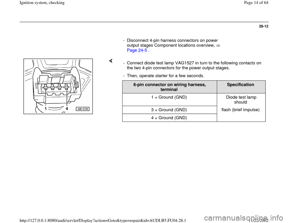
- Disconnect 4-pin harness connectors on power
output stages Component locations overview,
Page 24
-5 .
- Connect diode test lamp VAG1527 in turn to the following contacts on
the two 4-pin connectors for the power output stages.
- Then, operate starter for a few seconds.
6-pin connector on wiring harness,
terminal
Specification
1 + Ground (GND) Diode test lamp
should
3 + Ground (GND) flash (brief impulse)
4 + Ground (GND)
Pa
ge 14 of 64 I
gnition s
ystem, checkin
g
11/22/2002 htt
p://127.0.0.1:8080/audi/servlet/Dis
play?action=Goto&t
yp
e=re
pair&id=AUDI.B5.FU04.28.1
Page 15 of 64

28-13
If the specifications are not obtained:
- Switch ignition off.
- Connect test box VAG 1598/31 to wiring
harness for engine control module. Do not
connect to the engine control module itself.
Page 24
-20
.
The following wiring connections are to be checked for open circuits
and/or short to B+ or Ground (GND).
Black 4-pin connector on wiring
harness, terminal VAG1598/31 test box,
socket
1 94
3 110
4 102 Brown 4-pin connector on wiring
harness, terminal VAG1598/31 test box,
socket
1 95
3 111
4 103
Pa
ge 15 of 64 I
gnition s
ystem, checkin
g
11/22/2002 htt
p://127.0.0.1:8080/audi/servlet/Dis
play?action=Goto&t
yp
e=re
pair&id=AUDI.B5.FU04.28.1
Page 16 of 64

28-14
- Rectify any open/short circuit as necessary.
If no wiring malfunction is detected:
- Connect 4-pin connectors to power output
stages.
- Disconnect 3-pin connectors from power output
stages.
- Connect diode test lamp VAG1527 to battery
(B+) and to one of the 3 terminals on power
output stage.
- Operate starter for few seconds.
The diode test lamp should flash.
- Carry out test with all 3 terminals on each of the
3-pin connectors for the power output stages.
The diode test lamp should flash each time.
Pa
ge 16 of 64 I
gnition s
ystem, checkin
g
11/22/2002 htt
p://127.0.0.1:8080/audi/servlet/Dis
play?action=Goto&t
yp
e=re
pair&id=AUDI.B5.FU04.28.1
Page 17 of 64

28-15
If the diode test lamp does not flash when testing
one or more of the contacts:
Check the Ground (GND) connections for the
power output stages as follows:
- Disconnect 4-pin harness connectors from
power output stages.
- Connect diode test lamp VAG1527 to battery
(B+) and terminal 2 of each of the 4-pin
connectors in turn.
The diode test lamp should light up.
Pa
ge 17 of 64 I
gnition s
ystem, checkin
g
11/22/2002 htt
p://127.0.0.1:8080/audi/servlet/Dis
play?action=Goto&t
yp
e=re
pair&id=AUDI.B5.FU04.28.1
Page 18 of 64
28-16
- If diode test lamp does not light up, test for open
circuit in wiring using wiring diagram.
Electrical Wiring Diagrams, Troubleshooting &
Component Locations
If the diode test lamp lights up:
- Replace power output stage.
Note:
Before installing new power output stage coat
metal side with heat paste (part no. G 052 170
A1). The heat paste is used to prevent corrosion
between the power output stage and the
fastening point, it is also used to transfer heat
from the power output stage.
CAUTION!
Part numbers are only for reference, always
check with your parts department for latest
information.
Pa
ge 18 of 64 I
gnition s
ystem, checkin
g
11/22/2002 htt
p://127.0.0.1:8080/audi/servlet/Dis
play?action=Goto&t
yp
e=re
pair&id=AUDI.B5.FU04.28.1
Page 19 of 64
28-17
Intake Air Temperature (IAT) sensor -
G42, checking
Location of sensor and connector Page 24
-5 .
- Connect vehicle diagnostic, testing and
information system VAS 5051 or VAG1551 scan
tool and select engine electronics control
module by entering address word "01" Page
01
-9 . When doing this the ignition must be
switched on.
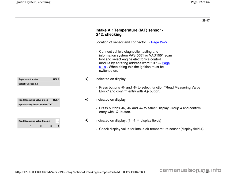
Rapid data transfer
HELP
Select Function XX
Indicated on display
- Press buttons -0- and -8- to select function "Read Measuring Value
Block" and confirm entry with -Q- button.
Read Measurin
g Value Block
HELP
Input Displa
y Group Number XXX
Indicated on display
- Press buttons -0-, -0- and -4- to select Display Group 4 and confirm
entry with -Q- button.
Read Measuring Value Block 4
1
2
3
4
Indicated on display: (1...4 display fields) - Check display value for intake air temperature sensor (display field 4):
Pa
ge 19 of 64 I
gnition s
ystem, checkin
g
11/22/2002 htt
p://127.0.0.1:8080/audi/servlet/Dis
play?action=Goto&t
yp
e=re
pair&id=AUDI.B5.FU04.28.1
Page 20 of 64
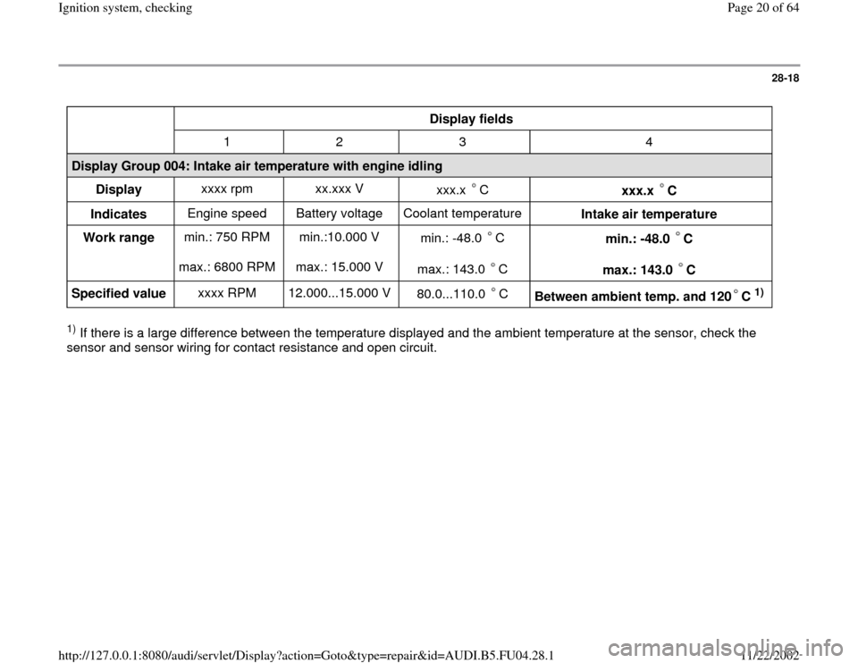
28-18
Display fields
1 2 3 4
Display Group 004: Intake air temperature with engine idling
Display xxxx rpm xx.xxx V
xxx.x C
xxx.x C
Indicates Engine speed Battery voltage Coolant temperature
Intake air temperature
Work range min.: 750 RPM
max.: 6800 RPM min.:10.000 V
max.: 15.000 V min.: -48.0 C
max.: 143.0 C
min.: -48.0 C
max.: 143.0 C
Specified value xxxx RPM 12.000...15.000 V
80.0...110.0 C
Between ambient temp. and 120 C
1)
1) If there is a large difference between the temperature displayed and the ambient temperature at the sensor, check the
sensor and sensor wiring for contact resistance and open circuit.
Pa
ge 20 of 64 I
gnition s
ystem, checkin
g
11/22/2002 htt
p://127.0.0.1:8080/audi/servlet/Dis
play?action=Goto&t
yp
e=re
pair&id=AUDI.B5.FU04.28.1