AUDI A4 1995 B5 / 1.G AWM Engine Assembly Workshop Manual
A4 1995 B5 / 1.G
AUDI
AUDI
https://www.carmanualsonline.info/img/6/934/w960_934-0.png
AUDI A4 1995 B5 / 1.G AWM Engine Assembly Workshop Manual
Page 1 of 47
13-1
Engine, disassembling and
assembling
Lock carrier, moving into service
position
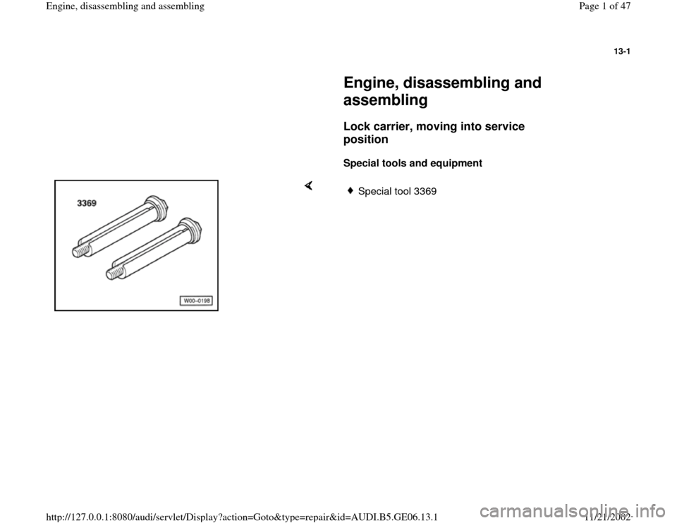
Special tools and equipment
Special tool 3369
Pa
ge 1 of 47 En
gine, disassemblin
g and assemblin
g
11/21/2002 htt
p://127.0.0.1:8080/audi/servlet/Dis
play?action=Goto&t
yp
e=re
pair&id=AUDI.B5.GE06.13.1
Page 2 of 47
13-2
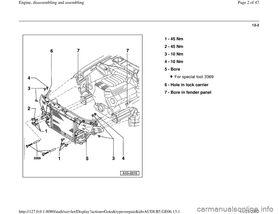
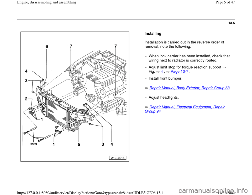
1 -
45 Nm
2 -
45 Nm
3 -
10 Nm
4 -
10 Nm
5 -
Bore
For special tool 3369
6 -
Hole in lock carrier
7 -
Bore in fender panel
Pa
ge 2 of 47 En
gine, disassemblin
g and assemblin
g
11/21/2002 htt
p://127.0.0.1:8080/audi/servlet/Dis
play?action=Goto&t
yp
e=re
pair&id=AUDI.B5.GE06.13.1
Page 3 of 47
13-3
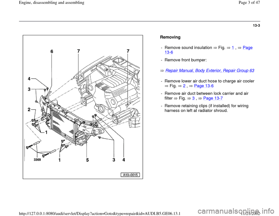
Removing
Repair Manual, Body Exterior, Repair Group 63
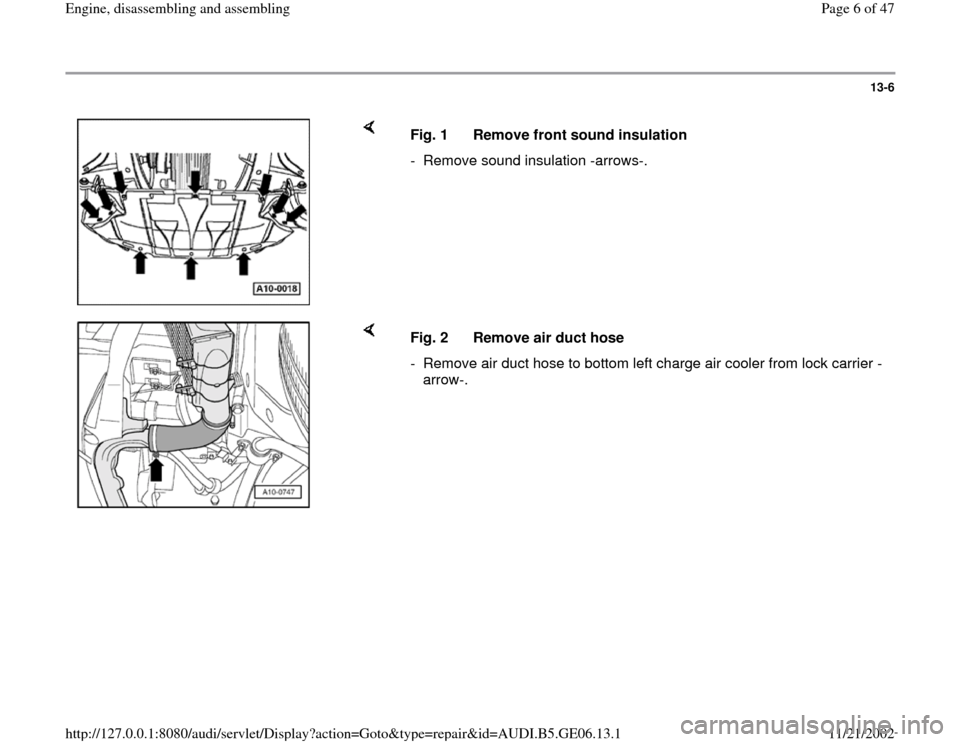
- Remove sound insulation Fig. 1
, Page
13
-6
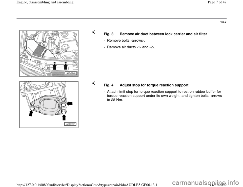
- Remove front bumper:- Remove lower air duct hose to charge air cooler
Fig. 2
, Page 13
-6
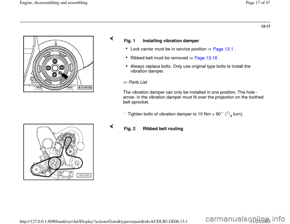
- Remove air duct between lock carrier and air
filter Fig. 3
, Page 13
-7
- Remove retaining clips (if installed) for wiring
harness on left at radiator shroud.
Pa
ge 3 of 47 En
gine, disassemblin
g and assemblin
g
11/21/2002 htt
p://127.0.0.1:8080/audi/servlet/Dis
play?action=Goto&t
yp
e=re
pair&id=AUDI.B5.GE06.13.1
Page 4 of 47
13-4
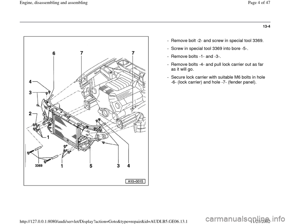
- Remove bolt -2- and screw in special tool 3369.
- Screw in special tool 3369 into bore -5-.
- Remove bolts -1- and -3-.
- Remove bolts -4- and pull lock carrier out as far
as it will go.
- Secure lock carrier with suitable M6 bolts in hole
-6- (lock carrier) and hole -7- (fender panel).
Pa
ge 4 of 47 En
gine, disassemblin
g and assemblin
g
11/21/2002 htt
p://127.0.0.1:8080/audi/servlet/Dis
play?action=Goto&t
yp
e=re
pair&id=AUDI.B5.GE06.13.1
Page 5 of 47
13-5
Installing
Installation is carried out in the reverse order of
removal; note the following:
Repair Manual, Body Exterior, Repair Group 63
Repair Manual, Electrical Equipment, Repair
Group 94
- When lock carrier has been installed, check that
wiring next to radiator is correctly routed.
- Adjust limit stop for torque reaction support
Fig. 4 , Page 13
-7 .
- Install front bumper.- Adjust headlights.
Pa
ge 5 of 47 En
gine, disassemblin
g and assemblin
g
11/21/2002 htt
p://127.0.0.1:8080/audi/servlet/Dis
play?action=Goto&t
yp
e=re
pair&id=AUDI.B5.GE06.13.1
Page 6 of 47
13-6
Fig. 1 Remove front sound insulation
- Remove sound insulation -arrows-.
Fig. 2 Remove air duct hose
- Remove air duct hose to bottom left charge air cooler from lock carrier -
arrow-.
Pa
ge 6 of 47 En
gine, disassemblin
g and assemblin
g
11/21/2002 htt
p://127.0.0.1:8080/audi/servlet/Dis
play?action=Goto&t
yp
e=re
pair&id=AUDI.B5.GE06.13.1
Page 7 of 47
13-7
Fig. 3 Remove air duct between lock carrier and air filter
- Remove bolts -arrows-.
- Remove air ducts -1- and -2-.
Fig. 4 Adjust stop for torque reaction support
- Attach limit stop for torque reaction support to rest on rubber buffer for
torque reaction support under its own weight, and tighten bolts -arrows-
to 28 Nm.
Pa
ge 7 of 47 En
gine, disassemblin
g and assemblin
g
11/21/2002 htt
p://127.0.0.1:8080/audi/servlet/Dis
play?action=Goto&t
yp
e=re
pair&id=AUDI.B5.GE06.13.1
Page 17 of 47
13-17
Parts List
The vibration damper can only be installed in one position. The hole -
arrow- in the vibration damper must fit over the projection on the toothed
belt sprocket. Fig. 1 Installing vibration damperLock carrier must be in service position Page 13
-1 .
Ribbed belt must be removed Page 13
-18
.
Always replace bolts. Only use original type bolts to install the
vibration damper.
-
Tighten bolts of vibration damper to 10 Nm + 90 (
1/4turn).
Fig. 2 Ribbed belt routing
Pa
ge 17 of 47 En
gine, disassemblin
g and assemblin
g
11/21/2002 htt
p://127.0.0.1:8080/audi/servlet/Dis
play?action=Goto&t
yp
e=re
pair&id=AUDI.B5.GE06.13.1
Page 19 of 47
13-19
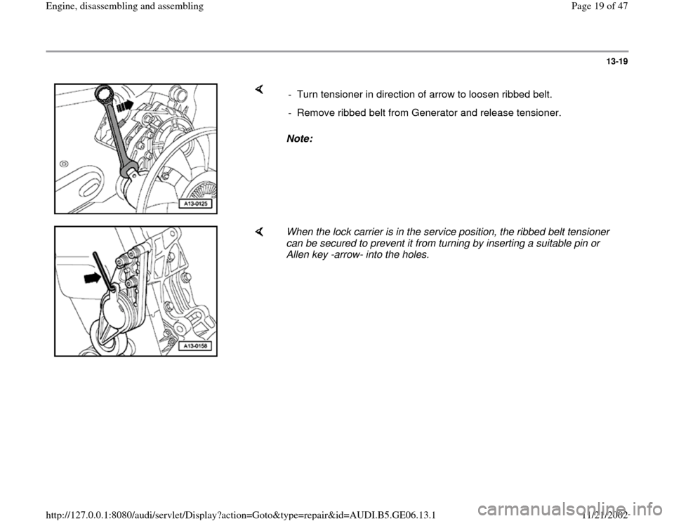
Note: - Turn tensioner in direction of arrow to loosen ribbed belt.
- Remove ribbed belt from Generator and release tensioner.
When the lock carrier is in the service position, the ribbed belt tensioner
can be secured to prevent it from turning by inserting a suitable pin or
Allen key -arrow- into the holes.
Pa
ge 19 of 47 En
gine, disassemblin
g and assemblin
g
11/21/2002 htt
p://127.0.0.1:8080/audi/servlet/Dis
play?action=Goto&t
yp
e=re
pair&id=AUDI.B5.GE06.13.1
Page 20 of 47
13-20
Installing
- Attach ribbed belt to pulleys from crankshaft and
vane pump and, if necessary, pull up with
auxiliary tool.
- Swivel tensioner for ribbed belt in direction of arrow.
- Install ribbed belt over Generator pulley last. Release tensioner.
- Check that ribbed belt is properly seated.
- Fit ribbed belt for A/C compressor.
Ribbed belt routing Fig. 2
, Page 13
-17
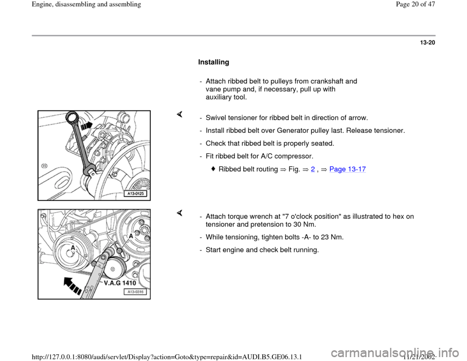
- Attach torque wrench at "7 o'clock position" as illustrated to hex on
tensioner and pretension to 30 Nm.
- While tensioning, tighten bolts -A- to 23 Nm.
- Start engine and check belt running.
Pa
ge 20 of 47 En
gine, disassemblin
g and assemblin
g
11/21/2002 htt
p://127.0.0.1:8080/audi/servlet/Dis
play?action=Goto&t
yp
e=re
pair&id=AUDI.B5.GE06.13.1
