relay AUDI A4 1995 B5 / 1.G Brakes Read Mesure Value Block Workshop Manual
[x] Cancel search | Manufacturer: AUDI, Model Year: 1995, Model line: A4, Model: AUDI A4 1995 B5 / 1.GPages: 79, PDF Size: 0.24 MB
Page 6 of 79

01-65
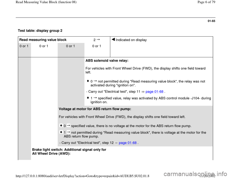
Test table: display group 2 Read measuring value block
2
Indicated on display
0 or 1
0 or 1
0 or 1
0 or 1
ABS solenoid valve relay:
For vehicles with Front Wheel Drive (FWD), the display shifts one field toward
left.
0 not permitted during "Read measuring value block", the relay was not
activated during "ignition on".
- Carry out "Electrical test", step 11 page 01
-68
.
1 specified value, relay was activated by ABS control module -J104- during
ignition on.
Voltage at motor for ABS return flow pump:
For vehicles with Front Wheel Drive (FWD), the display shifts one field toward left.
0 specified value, there is no voltage at the motor for the ABS return flow pump. 1 not permitted during "Read measuring value block", there is voltage at the motor for the
ABS return flow pump.
- Carry out "Electrical test", step 12 page 01
-68
.
Brake light switch: Additional signal only for
All Wheel Drive (AWD):
Pa
ge 6 of 79 Read Measurin
g Value Block
(function 08
)
11/20/2002 htt
p://127.0.0.1:8080/audi/servlet/Dis
play?action=Goto&t
yp
e=re
pair&id=AUDI.B5.SU02.01.8
Page 15 of 79

01-72
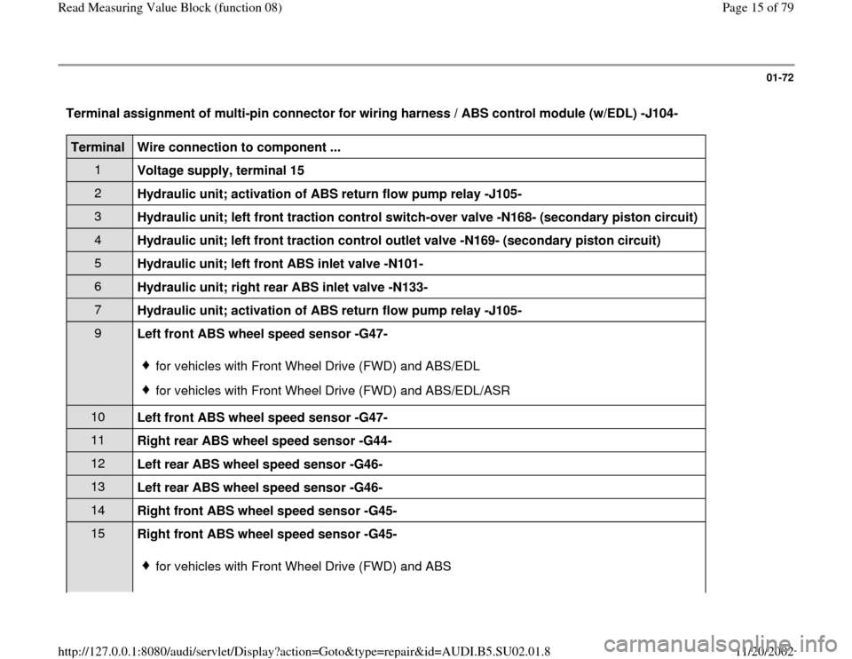
Terminal assignment of multi-pin connector for wiring harness / ABS control module (w/EDL) -J104- Terminal
Wire connection to component ...
1
Voltage supply, terminal 15 2
Hydraulic unit; activation of ABS return flow pump relay -J105- 3
Hydraulic unit; left front traction control switch-over valve -N168- (secondary piston circuit) 4
Hydraulic unit; left front traction control outlet valve -N169- (secondary piston circuit) 5
Hydraulic unit; left front ABS inlet valve -N101- 6
Hydraulic unit; right rear ABS inlet valve -N133- 7
Hydraulic unit; activation of ABS return flow pump relay -J105- 9
Left front ABS wheel speed sensor -G47-
for vehicles with Front Wheel Drive (FWD) and ABS/EDLfor vehicles with Front Wheel Drive (FWD) and ABS/EDL/ASR
10
Left front ABS wheel speed sensor -G47- 11
Right rear ABS wheel speed sensor -G44- 12
Left rear ABS wheel speed sensor -G46- 13
Left rear ABS wheel speed sensor -G46- 14
Right front ABS wheel speed sensor -G45- 15
Right front ABS wheel speed sensor -G45-
for vehicles with Front Wheel Drive (FWD) and ABS
Pa
ge 15 of 79 Read Measurin
g Value Block
(function 08
)
11/20/2002 htt
p://127.0.0.1:8080/audi/servlet/Dis
play?action=Goto&t
yp
e=re
pair&id=AUDI.B5.SU02.01.8
Page 19 of 79

01-74
Terminal
Wire connection to component ...
37
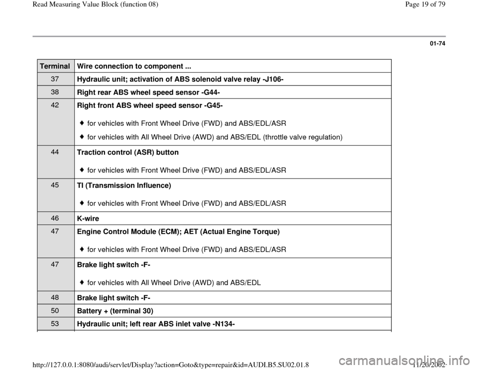
Hydraulic unit; activation of ABS solenoid valve relay -J106- 38
Right rear ABS wheel speed sensor -G44- 42
Right front ABS wheel speed sensor -G45-
for vehicles with Front Wheel Drive (FWD) and ABS/EDL/ASR for vehicles with All Wheel Drive (AWD) and ABS/EDL (throttle valve regulation)
44
Traction control (ASR) button
for vehicles with Front Wheel Drive (FWD) and ABS/EDL/ASR
45
TI (Transmission Influence)
for vehicles with Front Wheel Drive (FWD) and ABS/EDL/ASR
46
K-wire 47
Engine Control Module (ECM); AET (Actual Engine Torque)
for vehicles with Front Wheel Drive (FWD) and ABS/EDL/ASR
47
Brake light switch -F-
for vehicles with All Wheel Drive (AWD) and ABS/EDL
48
Brake light switch -F- 50
Battery + (terminal 30) 53
Hydraulic unit; left rear ABS inlet valve -N134-
Pa
ge 19 of 79 Read Measurin
g Value Block
(function 08
)
11/20/2002 htt
p://127.0.0.1:8080/audi/servlet/Dis
play?action=Goto&t
yp
e=re
pair&id=AUDI.B5.SU02.01.8
Page 26 of 79

01-79
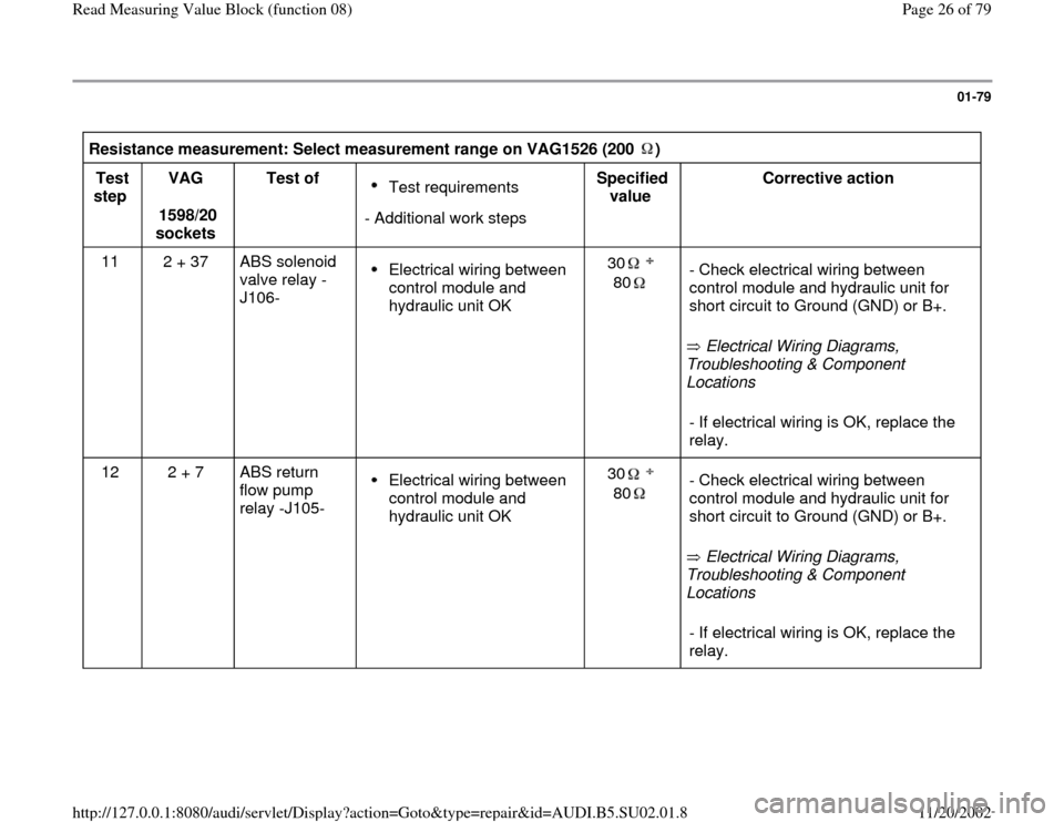
Resistance measurement: Select measurement range on VAG1526 (200 ) Test
step VAG
1598/20
sockets Test of
Test requirements
- Additional work stepsSpecified
value Corrective action
11 2 + 37 ABS solenoid
valve relay -
J106- Electrical wiring between
control module and
hydraulic unit OK 30
80
Electrical Wiring Diagrams,
Troubleshooting & Component
Locations - Check electrical wiring between
control module and hydraulic unit for
short circuit to Ground (GND) or B+. - If electrical wiring is OK, replace the
relay.
12 2 + 7 ABS return
flow pump
relay -J105-
Electrical wiring between
control module and
hydraulic unit OK 30
80
Electrical Wiring Diagrams,
Troubleshooting & Component
Locations - Check electrical wiring between
control module and hydraulic unit for
short circuit to Ground (GND) or B+. - If electrical wiring is OK, replace the
relay.
Pa
ge 26 of 79 Read Measurin
g Value Block
(function 08
)
11/20/2002 htt
p://127.0.0.1:8080/audi/servlet/Dis
play?action=Goto&t
yp
e=re
pair&id=AUDI.B5.SU02.01.8
Page 66 of 79

01-107
Output on
printer of
VAG1551 Scan
Tool (ST) Possible cause
Corrective action
DTC
00301
ABS return flow
pump -V39 -
Open circuit in wire or contact resistance
in Ground (GND) connection or voltage
supply to ABS return flow pump -V39-.
Open circuit or short circuit to B+ or
Ground (GND) in wiring between ABS
return flow pump relay -J105- and the
ABS control module -J104-.
ABS return flow pump relay -J105-, ABS
return flow pump -V39- or hydraulic unit
malfunctioning. Electrical Wiring Diagrams, Troubleshooting &
Component Locations
Electrical Wiring Diagrams, Troubleshooting &
Component Locations - Locate and repair open circuit or contact resistance.
- Locate and repair open circuit or short circuit.- Check ABS return flow pump relay -J105-, ABS return
flow pump -V39- and ABS hydraulic unit -N55-, carry out
"electrical test", step 12+17 page 01
-68
, "Read
measuring value block", display group 2 page 01
-65
.
Pa
ge 66 of 79 Read Measurin
g Value Block
(function 08
)
11/20/2002 htt
p://127.0.0.1:8080/audi/servlet/Dis
play?action=Goto&t
yp
e=re
pair&id=AUDI.B5.SU02.01.8
Page 67 of 79

01-108
Output on printer
of VAG1551 Scan
Tool (ST) Possible cause
Corrective action
DTC
00302
ABS solenoid
valve relay -J106-
Faulty wire connection or excessively large
contact resistance in Ground (GND)
connection to ABS solenoid valve relay -
J106-.
Open circuit or short circuit to B+ or Ground
(GND) in wiring between ABS solenoid
valve relay -J106- and the ABS control
module -J104-.
ABS solenoid valve relay -J106- or ABS
hydraulic unit -N55- malfunctioning. Electrical Wiring Diagrams, Troubleshooting &
Component Locations
Electrical Wiring Diagrams, Troubleshooting &
Component Locations - Check Ground (GND) connection for contact
resistance and faulty wiring.
- Locate and repair open circuit or short circuit.- Check ABS solenoid valve relay -J106- and ABS
hydraulic unit, carry out "electrical test", step 11
page 01
-68
, "Read measuring value block", display
group 2 page 01
-65
.
Pa
ge 67 of 79 Read Measurin
g Value Block
(function 08
)
11/20/2002 htt
p://127.0.0.1:8080/audi/servlet/Dis
play?action=Goto&t
yp
e=re
pair&id=AUDI.B5.SU02.01.8