wiring AUDI A4 1997 B5 / 1.G 01V Transmission Electrical Testing Workshop Manual
[x] Cancel search | Manufacturer: AUDI, Model Year: 1997, Model line: A4, Model: AUDI A4 1997 B5 / 1.GPages: 66, PDF Size: 0.28 MB
Page 2 of 66
01-274
Additional information
Repair Manual, 5 Spd. Automatic Transmission
01V,
Electrical Wiring Diagrams, Troubleshooting &
Component Locations"
Notes:
Use VAG1526A multimeter for the test. The
tables list which measures range needs to be
selected before taking each measurement.
The specified values are valid for an ambient
temperature of 0 to 40 C (32 to 104 F).
If the values obtained differ from the specified
values, determine the malfunction using the
applicable wiring diagram.
If the measured values only deviate slightly
from the specified values clean sockets and
connectors of testers and repeat test. Before
replacing a component, check wires and
connections. If the specified values are below
10 , repeat the resistance measurement on
the component.
Pa
ge 2 of 66 Electrical testin
g
11/20/2002 htt
p://127.0.0.1:8080/audi/servlet/Dis
play?action=Goto&t
yp
e=re
pair&id=AUDI.B5.AT02.01.16
Page 4 of 66
01-275
The contact numbers of the connector and the
socket numbers of VAG 1598/20 test box match
up page 01
-277
.
To check the multi-function switch, it is not
necessary to connect test box VAG 1598/20
because first the connectors for the multi-
function switch are checked.
CAUTION!
To avoid permanent damage of electronic
components, select the appropriate
measuring range on tester before connecting
the measuring leads.
Test requirements
Battery voltage OK
Fuses for Transmission Control Module
(TCM) OK
Electrical Wiring Diagrams, Troubleshooting &
Component Locations
Fuses for component being tested OK. The
fuse holder is behind a cover on the side of
Pa
ge 4 of 66 Electrical testin
g
11/20/2002 htt
p://127.0.0.1:8080/audi/servlet/Dis
play?action=Goto&t
yp
e=re
pair&id=AUDI.B5.AT02.01.16
Page 5 of 66
the instrument cluster.
Ground (GND) connections OK:
Check battery Ground (GND) strap and Ground
(GND) strap between body and transmission.
Check Ground (GND) connections for
Transmission Control Module (TCM).
Electrical Wiring Diagrams, Troubleshooting &
Component Locations
Pa
ge 5 of 66 Electrical testin
g
11/20/2002 htt
p://127.0.0.1:8080/audi/servlet/Dis
play?action=Goto&t
yp
e=re
pair&id=AUDI.B5.AT02.01.16
Page 6 of 66
01-276
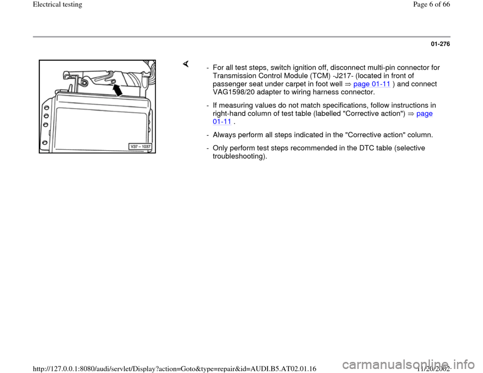
- For all test steps, switch ignition off, disconnect multi-pin connector for
Transmission Control Module (TCM) -J217- (located in front of
passenger seat under carpet in foot well page 01
-11
) and connect
VAG1598/20 adapter to wiring harness connector.
- If measuring values do not match specifications, follow instructions in
right-hand column of test table (labelled "Corrective action") page
01
-11
.
- Always perform all steps indicated in the "Corrective action" column.
- Only perform test steps recommended in the DTC table (selective
troubleshooting).
Pa
ge 6 of 66 Electrical testin
g
11/20/2002 htt
p://127.0.0.1:8080/audi/servlet/Dis
play?action=Goto&t
yp
e=re
pair&id=AUDI.B5.AT02.01.16
Page 7 of 66
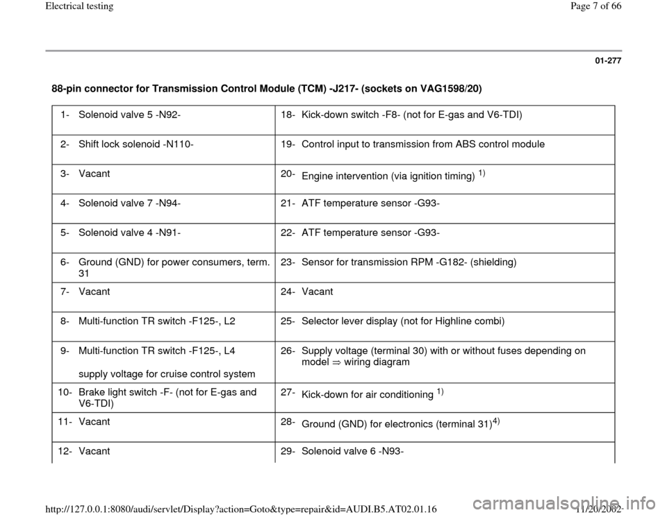
01-277
88-pin connector for Transmission Control Module (TCM) -J217- (sockets on VAG1598/20)
1- Solenoid valve 5 -N92- 18-
Kick-down switch -F8- (not for E-gas and V6-TDI)
2- Shift lock solenoid -N110- 19-
Control input to transmission from ABS control module
3- Vacant 20-
Engine intervention (via ignition timing)
1)
4- Solenoid valve 7 -N94- 21-
ATF temperature sensor -G93-
5- Solenoid valve 4 -N91- 22-
ATF temperature sensor -G93-
6- Ground (GND) for power consumers, term.
31 23-
Sensor for transmission RPM -G182- (shielding)
7- Vacant 24-
Vacant
8- Multi-function TR switch -F125-, L2 25-
Selector lever display (not for Highline combi)
9- Multi-function TR switch -F125-, L4
supply voltage for cruise control system 26-
Supply voltage (terminal 30) with or without fuses depending on
model wiring diagram
10-
Brake light switch -F- (not for E-gas and
V6-TDI) 27-
Kick-down for air conditioning
1)
11-
Vacant 28-
Ground (GND) for electronics (terminal 31)
4)
12- Vacant 29- Solenoid valve 6 -N93-
Pa
ge 7 of 66 Electrical testin
g
11/20/2002 htt
p://127.0.0.1:8080/audi/servlet/Dis
play?action=Goto&t
yp
e=re
pair&id=AUDI.B5.AT02.01.16
Page 12 of 66
01-280
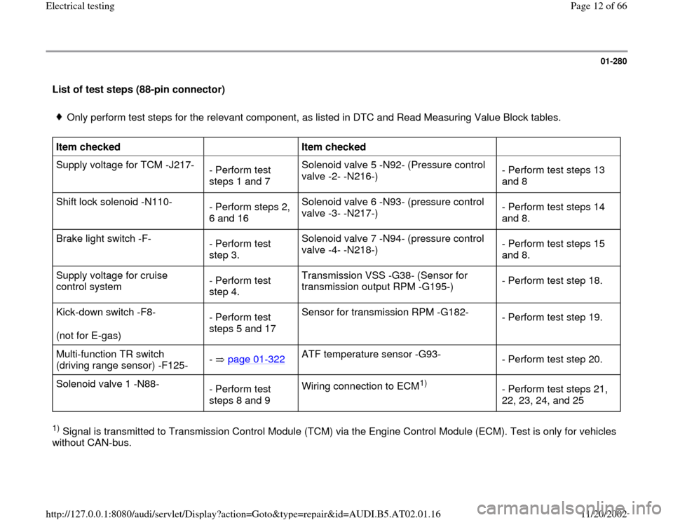
List of test steps (88-pin connector)
Only perform test steps for the relevant component, as listed in DTC and Read Measuring Value Block tables.
Item checked
Item checked
Supply voltage for TCM -J217-
- Perform test
steps 1 and 7 Solenoid valve 5 -N92- (Pressure control
valve -2- -N216-) - Perform test steps 13
and 8
Shift lock solenoid -N110-
- Perform steps 2,
6 and 16 Solenoid valve 6 -N93- (pressure control
valve -3- -N217-) - Perform test steps 14
and 8.
Brake light switch -F-
- Perform test
step 3. Solenoid valve 7 -N94- (pressure control
valve -4- -N218-) - Perform test steps 15
and 8.
Supply voltage for cruise
control system - Perform test
step 4. Transmission VSS -G38- (Sensor for
transmission output RPM -G195-) - Perform test step 18.
Kick-down switch -F8-
(not for E-gas) - Perform test
steps 5 and 17 Sensor for transmission RPM -G182-
- Perform test step 19.
Multi-function TR switch
(driving range sensor) -F125- - page 01
-322
ATF temperature sensor -G93-
- Perform test step 20.
Solenoid valve 1 -N88-
- Perform test
steps 8 and 9 Wiring connection to ECM
1)
- Perform test steps 21,
22, 23, 24, and 25
1) Signal is transmitted to Transmission Control Module (TCM) via the Engine Control Module (ECM). Test is only for vehicles
without CAN-bus.
Pa
ge 12 of 66 Electrical testin
g
11/20/2002 htt
p://127.0.0.1:8080/audi/servlet/Dis
play?action=Goto&t
yp
e=re
pair&id=AUDI.B5.AT02.01.16
Page 14 of 66
01-282
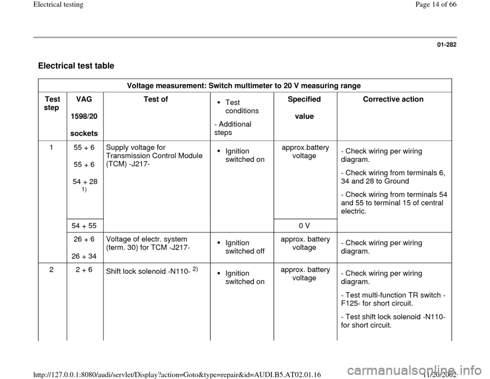
Electrical test table
Voltage measurement: Switch multimeter to 20 V measuring range
Test
step VAG
1598/20
sockets Test of
Test
conditions
- Additional
steps Specified
value Corrective action
1 55 + 6
55 + 6
54 + 28
1) Supply voltage for
Transmission Control Module
(TCM) -J217-
Ignition
switched on approx.battery
voltage - Check wiring per wiring
diagram.
- Check wiring from terminals 6,
34 and 28 to Ground
- Check wiring from terminals 54
and 55 to terminal 15 of central
electric.
54 + 55
0 V
26 + 6
26 + 34 Voltage of electr. system
(term. 30) for TCM -J217- Ignition
switched off approx. battery
voltage - Check wiring per wiring
diagram.
2 2 + 6
Shift lock solenoid -N110-
2)
Ignition
switched on approx. battery
voltage - Check wiring per wiring
diagram.
- Test multi-function TR switch -
F125- for short circuit.
- Test shift lock solenoid -N110-
for short circuit.
Pa
ge 14 of 66 Electrical testin
g
11/20/2002 htt
p://127.0.0.1:8080/audi/servlet/Dis
play?action=Goto&t
yp
e=re
pair&id=AUDI.B5.AT02.01.16
Page 16 of 66
01-283
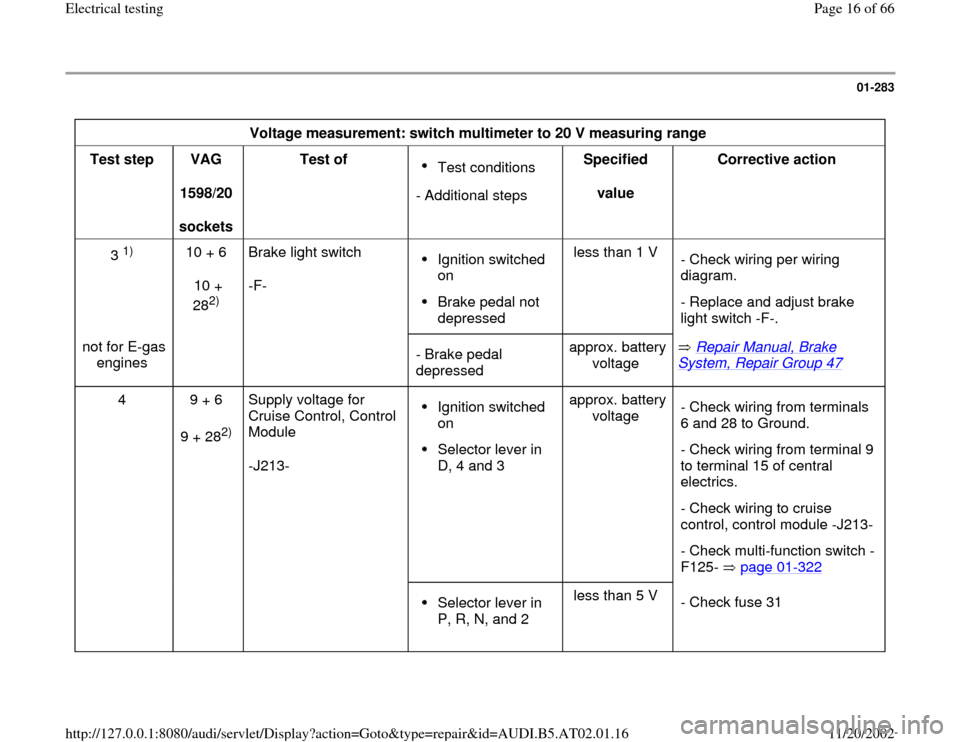
Voltage measurement: switch multimeter to 20 V measuring range
Test step
VAG
1598/20
sockets Test of
Test conditions
- Additional stepsSpecified
value Corrective action
3
1)
10 + 6
10 +
28
2) Brake light switch
-F-
Ignition switched
on Brake pedal not
depressed less than 1 V
- Check wiring per wiring
diagram.
- Replace and adjust brake
light switch -F-.
not for E-gas
engines
- Brake pedal
depressed approx. battery
voltage Repair Manual, Brake
System, Repair Group 47
4 9 + 6
9 + 28
2) Supply voltage for
Cruise Control, Control
Module
-J213-
Ignition switched
on Selector lever in
D, 4 and 3 approx. battery
voltage - Check wiring from terminals
6 and 28 to Ground.
- Check wiring from terminal 9
to terminal 15 of central
electrics.
- Check wiring to cruise
control, control module -J213-
- Check multi-function switch -
F125- page 01
-322
Selector lever in
P, R, N, and 2 less than 5 V
- Check fuse 31
Pa
ge 16 of 66 Electrical testin
g
11/20/2002 htt
p://127.0.0.1:8080/audi/servlet/Dis
play?action=Goto&t
yp
e=re
pair&id=AUDI.B5.AT02.01.16
Page 18 of 66
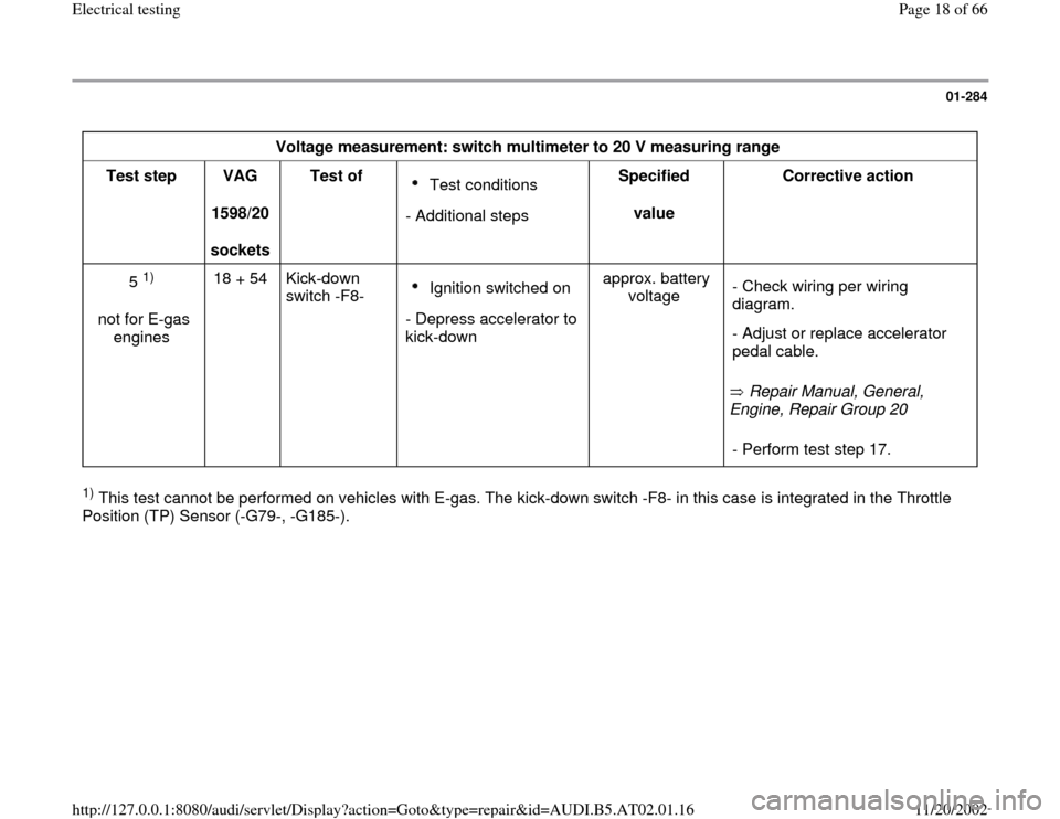
01-284
Voltage measurement: switch multimeter to 20 V measuring range
Test step
VAG
1598/20
sockets Test of
Test conditions
- Additional stepsSpecified
value Corrective action
5
1)
not for E-gas
engines 18 + 54 Kick-down
switch -F8-
Ignition switched on
- Depress accelerator to
kick-down approx. battery
voltage
Repair Manual, General,
Engine, Repair Group 20 - Check wiring per wiring
diagram.
- Adjust or replace accelerator
pedal cable.
- Perform test step 17.
1) This test cannot be performed on vehicles with E-gas. The kick-down switch -F8- in this case is integrated in the Throttle
Position (TP) Sensor (-G79-, -G185-).
Pa
ge 18 of 66 Electrical testin
g
11/20/2002 htt
p://127.0.0.1:8080/audi/servlet/Dis
play?action=Goto&t
yp
e=re
pair&id=AUDI.B5.AT02.01.16
Page 19 of 66
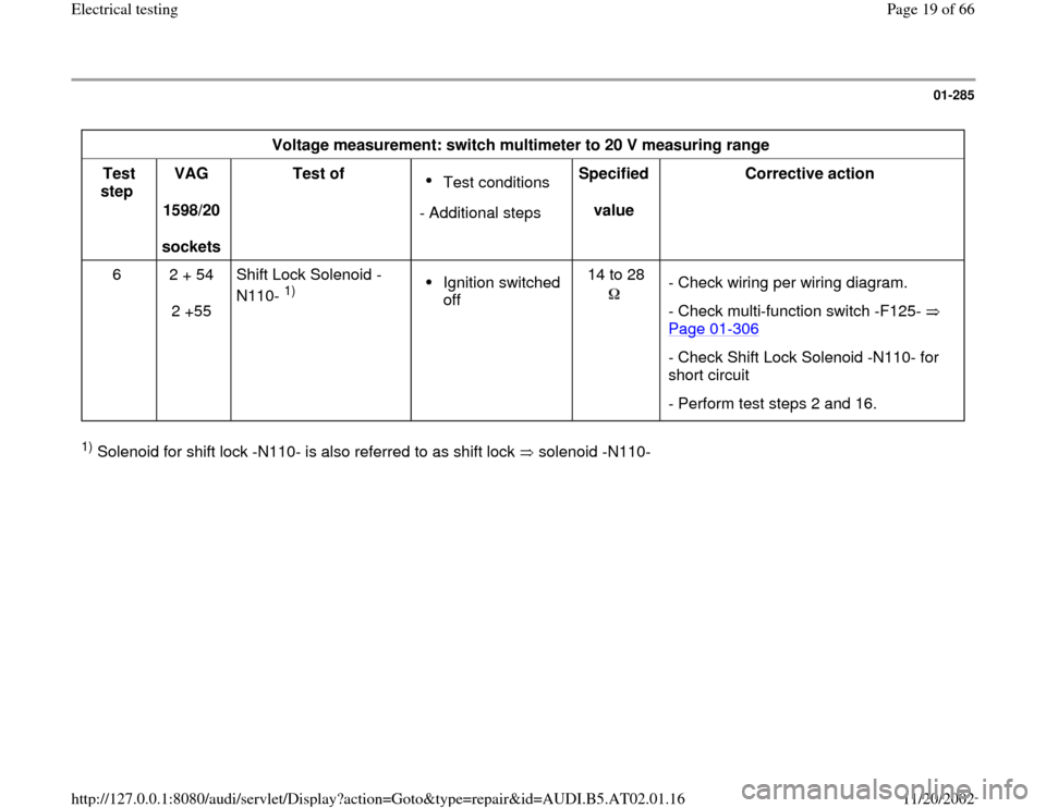
01-285
Voltage measurement: switch multimeter to 20 V measuring range
Test
step VAG
1598/20
sockets Test of
Test conditions
- Additional stepsSpecified
value Corrective action
6
2 + 54
2 +55 Shift Lock Solenoid -
N110-
1)
Ignition switched
off 14 to 28
- Check wiring per wiring diagram.
- Check multi-function switch -F125-
Page 01
-306
- Check Shift Lock Solenoid -N110- for
short circuit
- Perform test steps 2 and 16.
1) Solenoid for shift lock -N110- is also referred to as shift lock solenoid -N110-
Pa
ge 19 of 66 Electrical testin
g
11/20/2002 htt
p://127.0.0.1:8080/audi/servlet/Dis
play?action=Goto&t
yp
e=re
pair&id=AUDI.B5.AT02.01.16