AUDI A4 1997 B5 / 1.G Suspension Front Axle Components Workshop Manual
Manufacturer: AUDI, Model Year: 1997,
Model line: A4,
Model: AUDI A4 1997 B5 / 1.G
Pages: 26, PDF Size: 0.33 MB
AUDI A4 1997 B5 / 1.G Suspension Front Axle Components Workshop Manual
A4 1997 B5 / 1.G
AUDI
AUDI
https://www.carmanualsonline.info/img/6/1157/w960_1157-0.png
AUDI A4 1997 B5 / 1.G Suspension Front Axle Components Workshop Manual
Trending: wheel, wheel bolts, warning light, wiring, ABS, engine, boot
Page 1 of 26
40-17
Front drive axles, removing
and installing
WARNING!
Do not re-use any fasteners that are worn or
deformed in normal use.
Some fasteners are designed to be used only
once, and are unreliable and may fail if used
a second time. This includes, but is not
limited to, nuts, bolts, washers, circlips and
cotter pins. Always follow the
recommendations in this manual-replace
these fasteners with new parts where
indicated, and any other time it is deemed
necessary by inspection.
Removing
- Remove wheel trim.
On light-alloy wheels use puller in vehicle tool kit
to remove trim cap
- Remove collar bolt for drive axle.
WARNING!
The vehicle must be standing on its wheels
Pa
ge 1 of 26 Front drive axles, removin
g and installin
g
11/20/2002 htt
p://127.0.0.1:8080/audi/servlet/Dis
play?action=Goto&t
yp
e=re
pair&id=AUDI.B5.SU01.40.3
Page 2 of 26
when loosening or tightening the collar bolt
for the drive axle (item - 17 -, page Page 40
-
4 ). Otherwise the risk of an accident exists.
- Remove wheel.
Pa
ge 2 of 26 Front drive axles, removin
g and installin
g
11/20/2002 htt
p://127.0.0.1:8080/audi/servlet/Dis
play?action=Goto&t
yp
e=re
pair&id=AUDI.B5.SU01.40.3
Page 3 of 26
40-18
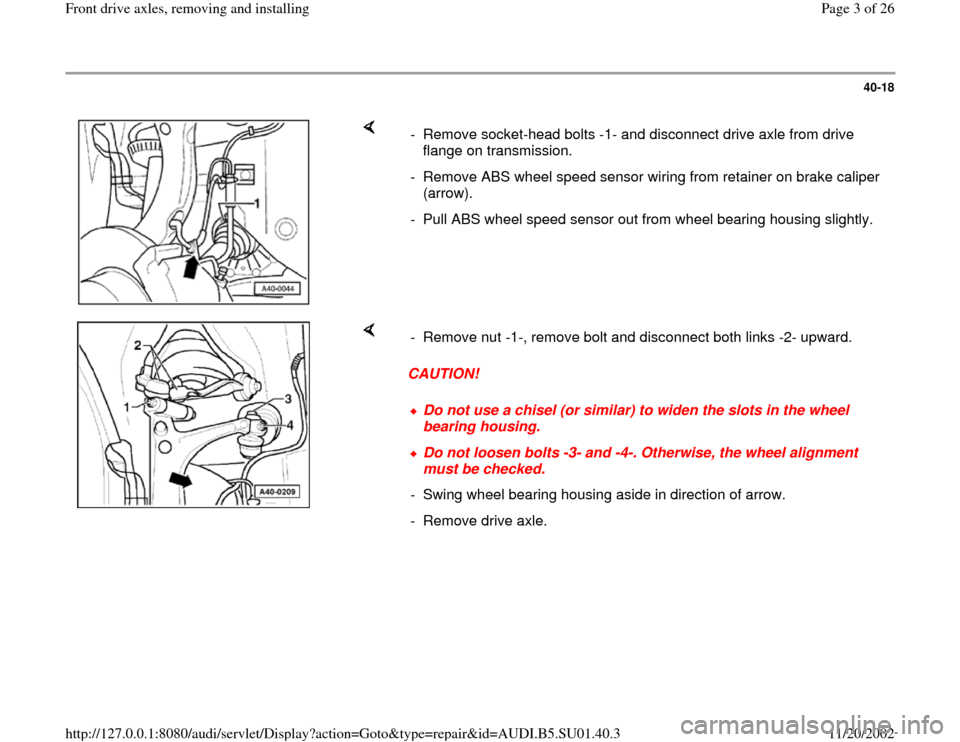
- Remove socket-head bolts -1- and disconnect drive axle from drive
flange on transmission.
- Remove ABS wheel speed sensor wiring from retainer on brake caliper
(arrow).
- Pull ABS wheel speed sensor out from wheel bearing housing slightly.
CAUTION! - Remove nut -1-, remove bolt and disconnect both links -2- upward.
Do not use a chisel (or similar) to widen the slots in the wheel
bearing housing. Do not loosen bolts -3- and -4-. Otherwise, the wheel alignment
must be checked.
- Swing wheel bearing housing aside in direction of arrow.
- Remove drive axle.
Pa
ge 3 of 26 Front drive axles, removin
g and installin
g
11/20/2002 htt
p://127.0.0.1:8080/audi/servlet/Dis
play?action=Goto&t
yp
e=re
pair&id=AUDI.B5.SU01.40.3
Page 4 of 26
40-19
Installing
- Install drive axle into wheel bearing housing and
bolt it to drive flange on transmission.
- Install both upper links and tighten nut to 40 Nm
(30 ft lb).
When tightening, press upper links downward as
far as possible
- Fully tighten bolts connecting drive axle to drive
flange on transmission.
M8 bolts: 40 Nm (30 ft lb)
M10 bolts: 80 Nm (59 ft lb)
- Push ABS wheel speed sensor into wheel
bearing housing up to stop and insert sensor
wiring into retainer on brake caliper.
- Install wheel.
- Install and tighten new bolt for drive axle.
M14 bolt: 115 Nm (85 ft lb) + 1/2-turn (180
Pa
ge 4 of 26 Front drive axles, removin
g and installin
g
11/20/2002 htt
p://127.0.0.1:8080/audi/servlet/Dis
play?action=Goto&t
yp
e=re
pair&id=AUDI.B5.SU01.40.3
Page 5 of 26
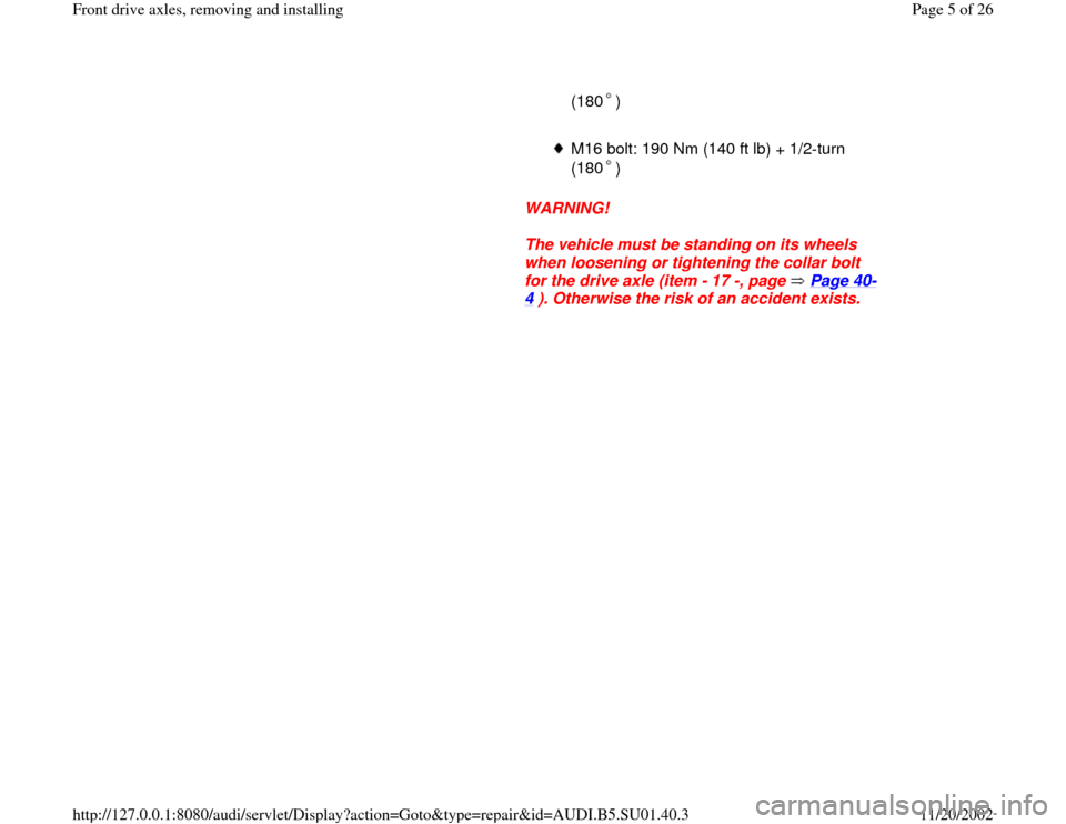
(180 )
M16 bolt: 190 Nm (140 ft lb) + 1/2-turn
(180 )
WARNING!
The vehicle must be standing on its wheels
when loosening or tightening the collar bolt
for the drive axle (item - 17 -, page Page 40
-
4 ). Otherwise the risk of an accident exists.
Pa
ge 5 of 26 Front drive axles, removin
g and installin
g
11/20/2002 htt
p://127.0.0.1:8080/audi/servlet/Dis
play?action=Goto&t
yp
e=re
pair&id=AUDI.B5.SU01.40.3
Page 6 of 26
40-20
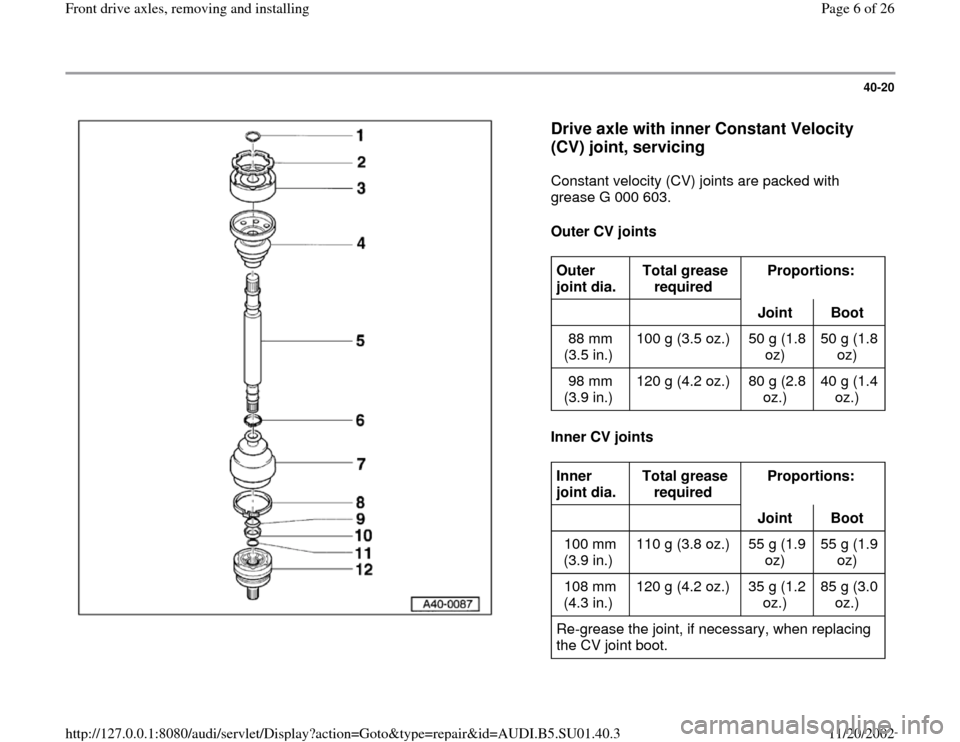
Drive axle with inner Constant Velocity
(CV) joint, servicing
Constant velocity (CV) joints are packed with
grease G 000 603.
Outer CV joints
Inner CV joints
Outer
joint dia. Total grease
required Proportions:
Joint
Boot
88 mm
(3.5 in.) 100 g (3.5 oz.) 50 g (1.8
oz) 50 g (1.8
oz)
98 mm
(3.9 in.) 120 g (4.2 oz.) 80 g (2.8
oz.) 40 g (1.4
oz.) Inner
joint dia. Total grease
required Proportions:
Joint
Boot
100 mm
(3.9 in.) 110 g (3.8 oz.) 55 g (1.9
oz) 55 g (1.9
oz)
108 mm
(4.3 in.) 120 g (4.2 oz.) 35 g (1.2
oz.) 85 g (3.0
oz.)
Re-grease the joint, if necessary, when replacing
the CV joint boot.
Pa
ge 6 of 26 Front drive axles, removin
g and installin
g
11/20/2002 htt
p://127.0.0.1:8080/audi/servlet/Dis
play?action=Goto&t
yp
e=re
pair&id=AUDI.B5.SU01.40.3
Page 7 of 26
40-21
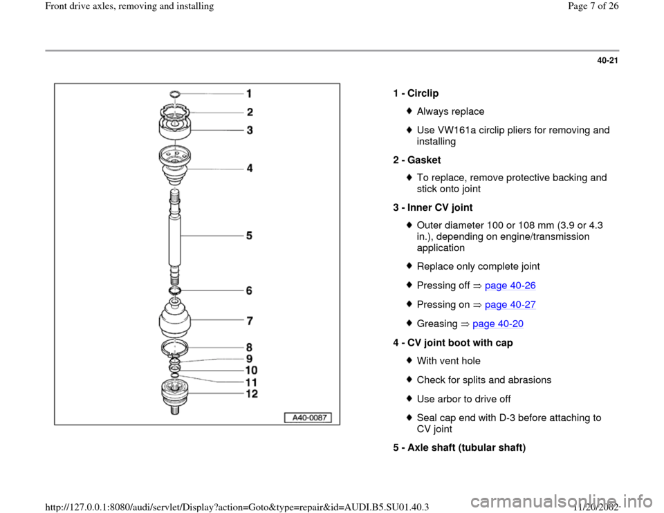
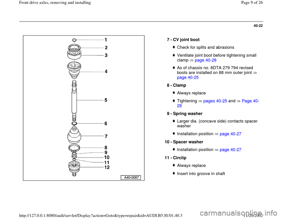
1 -
Circlip
Always replaceUse VW161a circlip pliers for removing and
installing
2 -
Gasket To replace, remove protective backing and
stick onto joint
3 -
Inner CV joint Outer diameter 100 or 108 mm (3.9 or 4.3
in.), depending on engine/transmission
application Replace only complete jointPressing off page 40
-26
Pressing on page 40
-27
Greasing page 40
-20
4 -
CV joint boot with cap
With vent holeCheck for splits and abrasionsUse arbor to drive offSeal cap end with D-3 before attaching to
CV joint
5 -
Axle shaft (tubular shaft)
Pa
ge 7 of 26 Front drive axles, removin
g and installin
g
11/20/2002 htt
p://127.0.0.1:8080/audi/servlet/Dis
play?action=Goto&t
yp
e=re
pair&id=AUDI.B5.SU01.40.3
Page 8 of 26
6 -
Clamp
Always replace
Pa
ge 8 of 26 Front drive axles, removin
g and installin
g
11/20/2002 htt
p://127.0.0.1:8080/audi/servlet/Dis
play?action=Goto&t
yp
e=re
pair&id=AUDI.B5.SU01.40.3
Page 9 of 26
40-22
7 -
CV joint boot
Check for splits and abrasionsVentilate joint boot before tightening small
clamp page 40
-28
As of chassis no. 8DTA 279 794 revised
boots are installed on 88 mm outer joint
page 40
-25
8 -
Clamp
Always replaceTightening pages 40
-25
and Page 40
-
28
9 -
Spring washer
Larger dia. (concave side) contacts spacer
washer Installation position page 40
-27
10 -
Spacer washer
Installation position page 40
-27
11 -
Circlip
Always replaceInsert into groove in shaft
Pa
ge 9 of 26 Front drive axles, removin
g and installin
g
11/20/2002 htt
p://127.0.0.1:8080/audi/servlet/Dis
play?action=Goto&t
yp
e=re
pair&id=AUDI.B5.SU01.40.3
Page 10 of 26
40-23
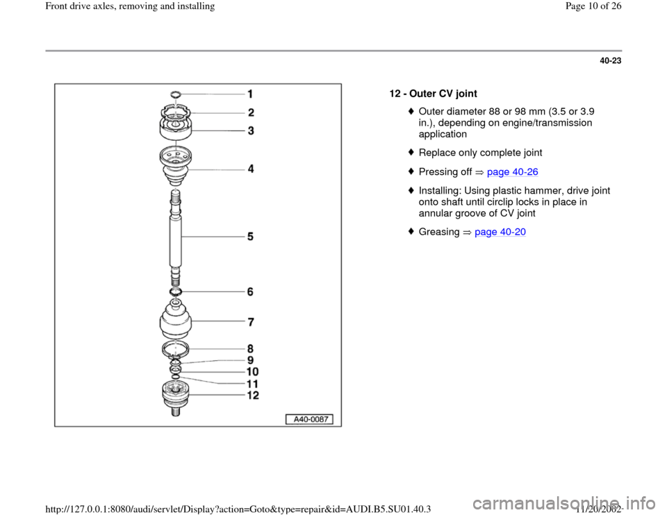
12 -
Outer CV joint
Outer diameter 88 or 98 mm (3.5 or 3.9
in.), depending on engine/transmission
application Replace only complete jointPressing off page 40
-26
Installing: Using plastic hammer, drive joint
onto shaft until circlip locks in place in
annular groove of CV joint Greasing page 40
-20
Pa
ge 10 of 26 Front drive axles, removin
g and installin
g
11/20/2002 htt
p://127.0.0.1:8080/audi/servlet/Dis
play?action=Goto&t
yp
e=re
pair&id=AUDI.B5.SU01.40.3
Trending: boot, wheel, engine, sensor, wheel torque, wiring, wheel alignment
