display AUDI A4 1998 B5 / 1.G AC System On Board Diagnostic Service Manual
[x] Cancel search | Manufacturer: AUDI, Model Year: 1998, Model line: A4, Model: AUDI A4 1998 B5 / 1.GPages: 91, PDF Size: 0.32 MB
Page 63 of 91
01-45
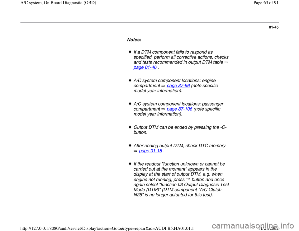
Notes:
If a DTM component fails to respond as
specified, perform all corrective actions, checks
and tests recommended in output DTM table
page 01
-46
.
A/C system component locations: engine
compartment page 87
-96
(note specific
model year information).
A/C system component locations: passenger
compartment page 87
-106
(note specific
model year information).
Output DTM can be ended by pressing the -C-
button.
After ending output DTM, check DTC memory
page 01
-18
.
If the readout "function unknown or cannot be
carried out at the moment" appears in the
display at the start of output DTM, e.g. when
engine not running, press button and once
again select "function 03 Output Diagnosis Test
Mode (DTM)" (DTM component "A/C Clutch
N25" is no longer actuated for this test).
Pa
ge 63 of 91 A/C s
ystem, On Board Dia
gnostic
(OBD
)
11/21/2002 htt
p://127.0.0.1:8080/audi/servlet/Dis
play?action=Goto&t
yp
e=re
pair&id=AUDI.B5.HA01.01.1
Page 64 of 91

If the readout "function unknown or cannot be
carried out at the moment" appears in the
display page 01
-63
, Read measuring value
block (display group 1).
Function is unknown or cannot be carried out at the moment!
Indicated on display
- If this readout appears in the display, output Diagnostic Test Mode
(DTM) is ended.
- VAG1551 Scan Tool (ST) can be returned to the function mode by
pressing the button.
Pa
ge 64 of 91 A/C s
ystem, On Board Dia
gnostic
(OBD
)
11/21/2002 htt
p://127.0.0.1:8080/audi/servlet/Dis
play?action=Goto&t
yp
e=re
pair&id=AUDI.B5.HA01.01.1
Page 65 of 91
01-46
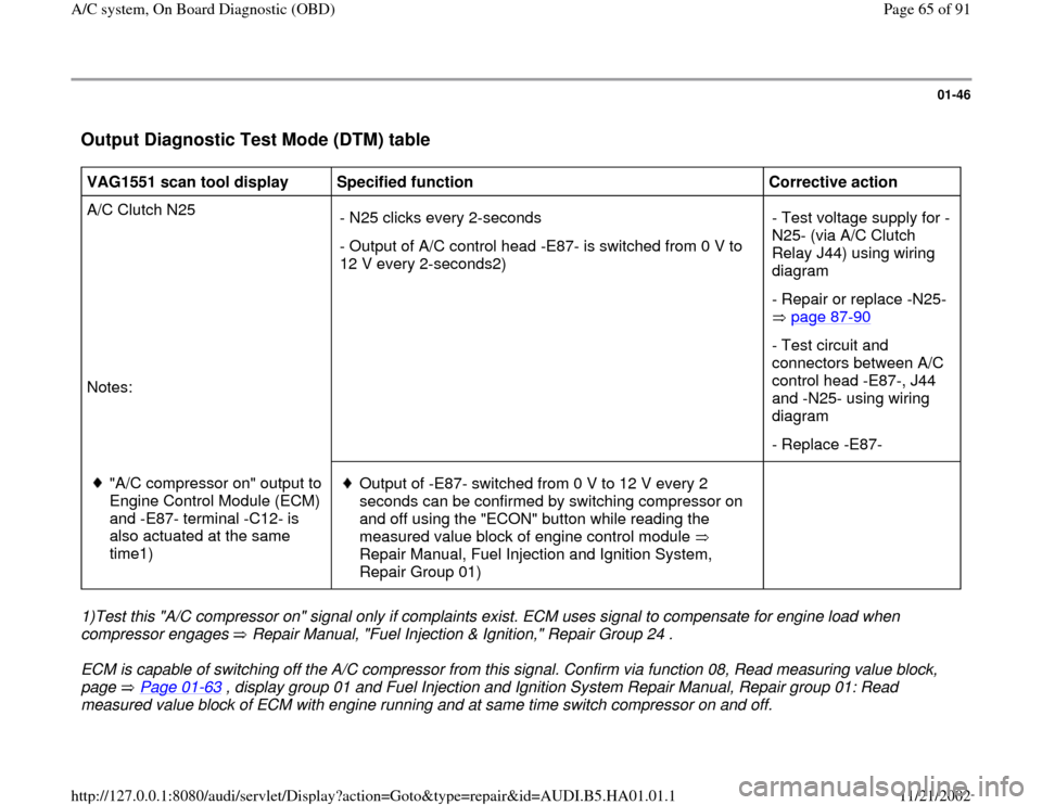
Output Diagnostic Test Mode (DTM) table
VAG1551 scan tool display
Specified function
Corrective action
A/C Clutch N25
Notes: - N25 clicks every 2-seconds
- Output of A/C control head -E87- is switched from 0 V to
12 V every 2-seconds2) - Test voltage supply for -
N25- (via A/C Clutch
Relay J44) using wiring
diagram
- Repair or replace -N25-
page 87
-90
- Test circuit and
connectors between A/C
control head -E87-, J44
and -N25- using wiring
diagram
- Replace -E87-
"A/C compressor on" output to
Engine Control Module (ECM)
and -E87- terminal -C12- is
also actuated at the same
time1)
Output of -E87- switched from 0 V to 12 V every 2
seconds can be confirmed by switching compressor on
and off using the "ECON" button while reading the
measured value block of engine control module
Repair Manual, Fuel Injection and Ignition System,
Repair Group 01)
1)Test this "A/C compressor on" signal only if complaints exist. ECM uses signal to compensate for engine load when
compressor engages Repair Manual, "Fuel Injection & Ignition," Repair Group 24 . ECM is capable of switching off the A/C compressor from this signal. Confirm via function 08, Read measuring value block,
page Page 01
-63
, display group 01 and Fuel Injection and Ignition System Repair Manual, Repair group 01: Read
measured value block of ECM with engine running and at same time switch compressor on and off.
Pa
ge 65 of 91 A/C s
ystem, On Board Dia
gnostic
(OBD
)
11/21/2002 htt
p://127.0.0.1:8080/audi/servlet/Dis
play?action=Goto&t
yp
e=re
pair&id=AUDI.B5.HA01.01.1
Page 67 of 91
01-47
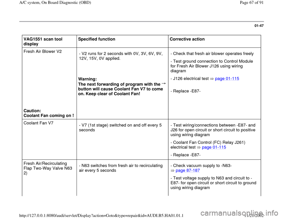
VAG1551 scan tool
display Specified function
Corrective action
Fresh Air Blower V2
Caution:
Coolant Fan coming on !
Warning:
The next forwarding of program with the
button will cause Coolant Fan V7 to come
on. Keep clear of Coolant Fan! - V2 runs for 2 seconds with 0V, 3V, 6V, 9V,
12V, 15V, 0V applied.
- Check that fresh air blower operates freely
- Test ground connection to Control Module
for Fresh Air Blower J126 using wiring
diagram
- J126 electrical test page 01
-115
- Replace -E87-
Coolant Fan V7
- V7 (1st stage) switched on and off every 5
seconds - Test wiring/connections between -E87- and
J26 for open circuit or short circuit to positive
using wiring diagram
- Coolant Fan Control (FC) Relay J261)
electrical test page 01
-115
- Replace -E87-
Fresh Air/Recirculating
Flap Two-Way Valve N63
2) - N63 switches from fresh air to recirculating
air every 5 seconds - Check vacuum supply to -N63-
page 87
-187
- Test voltage supply to N63 and circuit to -
E87- for open circuit or short circuit to ground
using wiring diagram
Pa
ge 67 of 91 A/C s
ystem, On Board Dia
gnostic
(OBD
)
11/21/2002 htt
p://127.0.0.1:8080/audi/servlet/Dis
play?action=Goto&t
yp
e=re
pair&id=AUDI.B5.HA01.01.1
Page 69 of 91
01-48
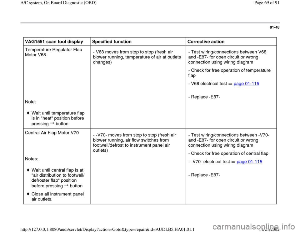
VAG1551 scan tool display
Specified function
Corrective action
Temperature Regulator Flap
Motor V68
Note:
Wait until temperature flap
is in "heat" position before
pressing button
- V68 moves from stop to stop (fresh air
blower running, temperature of air at outlets
changes) - Test wiring/connections between V68
and -E87- for open circuit or wrong
connection using wiring diagram
- Check for free operation of temperature
flap
- V68 electrical test page 01
-115
- Replace -E87-
Central Air Flap Motor V70
Notes:
Wait until central flap is at
"air distribution to footwell/
defroster flap" position
before pressing button Close all instrument panel
air outlets. - -V70- moves from stop to stop (fresh air
blower running, air flow switches from
footwell/defrost to instrument panel air
outlets) - Test wiring/connections between -V70-
and -E87- for open circuit or wrong
connection using wiring diagram
- Check for free operation of central flap
- -V70- electrical test page 01
-115
- Replace -E87-
Pa
ge 69 of 91 A/C s
ystem, On Board Dia
gnostic
(OBD
)
11/21/2002 htt
p://127.0.0.1:8080/audi/servlet/Dis
play?action=Goto&t
yp
e=re
pair&id=AUDI.B5.HA01.01.1
Page 70 of 91
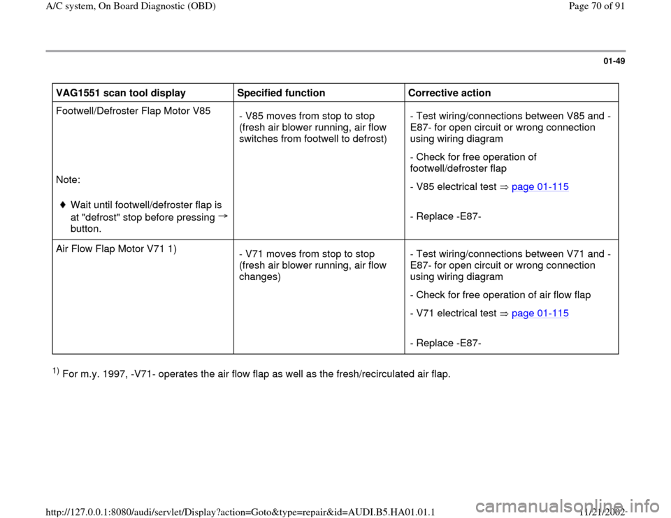
01-49
VAG1551 scan tool display
Specified function
Corrective action
Footwell/Defroster Flap Motor V85
Note:
Wait until footwell/defroster flap is
at "defrost" stop before pressing
button.
- V85 moves from stop to stop
(fresh air blower running, air flow
switches from footwell to defrost) - Test wiring/connections between V85 and -
E87- for open circuit or wrong connection
using wiring diagram
- Check for free operation of
footwell/defroster flap
- V85 electrical test page 01
-115
- Replace -E87-
Air Flow Flap Motor V71 1)
- V71 moves from stop to stop
(fresh air blower running, air flow
changes) - Test wiring/connections between V71 and -
E87- for open circuit or wrong connection
using wiring diagram
- Check for free operation of air flow flap
- V71 electrical test page 01
-115
- Replace -E87-
1) For m.y. 1997, -V71- operates the air flow flap as well as the fresh/recirculated air flap.
Pa
ge 70 of 91 A/C s
ystem, On Board Dia
gnostic
(OBD
)
11/21/2002 htt
p://127.0.0.1:8080/audi/servlet/Dis
play?action=Goto&t
yp
e=re
pair&id=AUDI.B5.HA01.01.1
Page 71 of 91
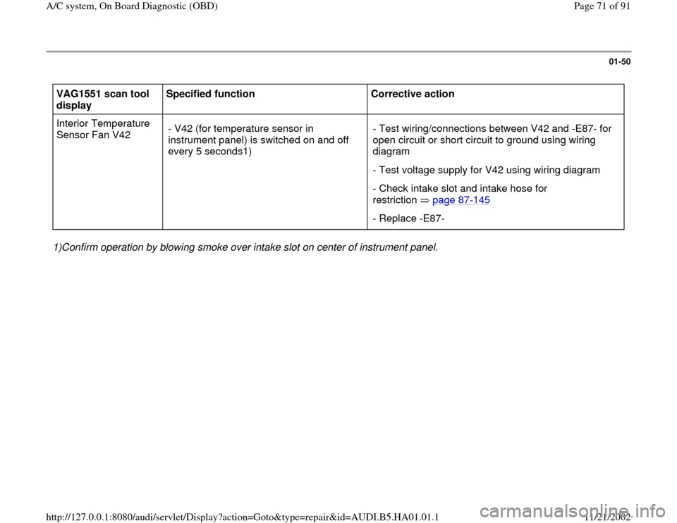
01-50
VAG1551 scan tool
display Specified function
Corrective action
Interior Temperature
Sensor Fan V42 - V42 (for temperature sensor in
instrument panel) is switched on and off
every 5 seconds1) - Test wiring/connections between V42 and -E87- for
open circuit or short circuit to ground using wiring
diagram
- Test voltage supply for V42 using wiring diagram
- Check intake slot and intake hose for
restriction page 87
-145
- Replace -E87-
1)Confirm operation by blowing smoke over intake slot on center of instrument panel.
Pa
ge 71 of 91 A/C s
ystem, On Board Dia
gnostic
(OBD
)
11/21/2002 htt
p://127.0.0.1:8080/audi/servlet/Dis
play?action=Goto&t
yp
e=re
pair&id=AUDI.B5.HA01.01.1
Page 72 of 91
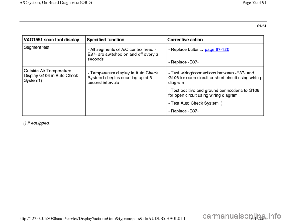
01-51
VAG1551 scan tool display
Specified function
Corrective action
Segment test
- All segments of A/C control head -
E87- are switched on and off every 3
seconds - Replace bulbs page 87
-126
- Replace -E87-
Outside Air Temperature
Display G106 in Auto Check
System1) - Temperature display in Auto Check
System1) begins counting up at 3
second intervals - Test wiring/connections between -E87- and
G106 for open circuit or short circuit using wiring
diagram
- Test positive and ground connections to G106
for open circuit using wiring diagram
- Test Auto Check System1)
- Replace -E87-
1) If equipped.
Pa
ge 72 of 91 A/C s
ystem, On Board Dia
gnostic
(OBD
)
11/21/2002 htt
p://127.0.0.1:8080/audi/servlet/Dis
play?action=Goto&t
yp
e=re
pair&id=AUDI.B5.HA01.01.1
Page 73 of 91
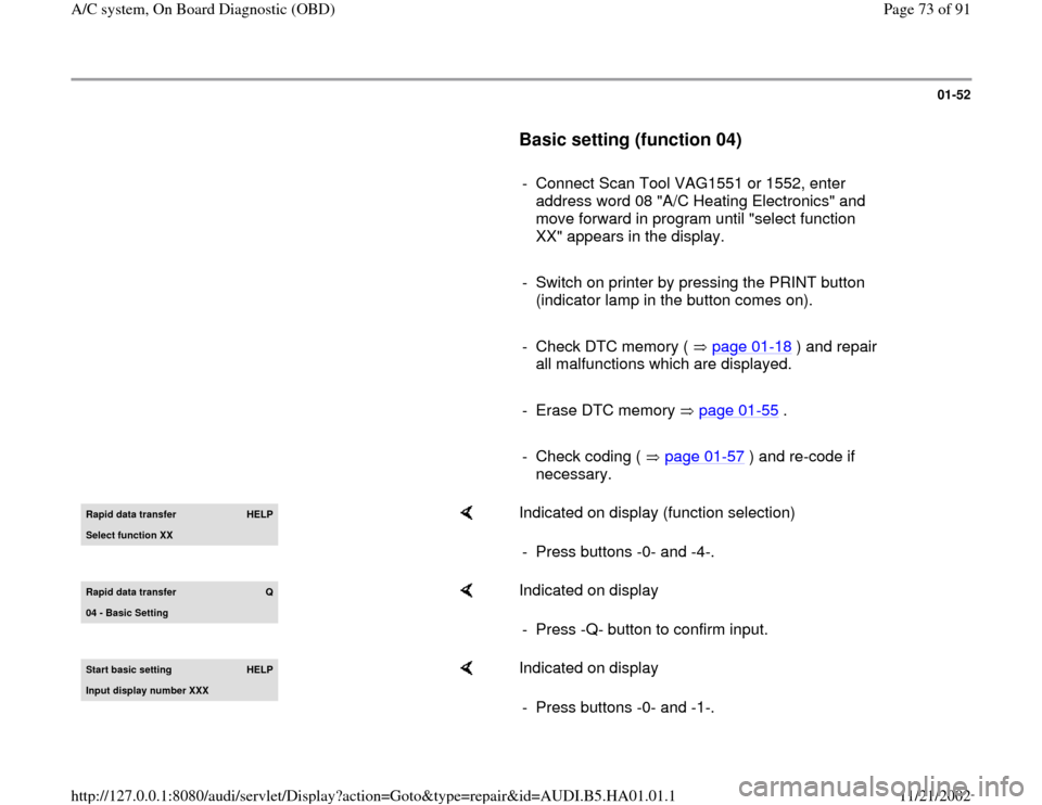
01-52
Basic setting (function 04)
- Connect Scan Tool VAG1551 or 1552, enter
address word 08 "A/C Heating Electronics" and
move forward in program until "select function
XX" appears in the display.
- Switch on printer by pressing the PRINT button
(indicator lamp in the button comes on).
- Check DTC memory ( page 01
-18
) and repair
all malfunctions which are displayed.
- Erase DTC memory page 01
-55
.
- Check coding ( page 01
-57
) and re-code if
necessary.
Rapid data transfer
HELP
Select function XX
Indicated on display (function selection)
- Press buttons -0- and -4-.
Rapid data transfer
Q
04 - Basic Settin
g
Indicated on display
- Press -Q- button to confirm input.
Start basic settin
g
HELP
Input display number XXX
Indicated on display
- Press buttons -0- and -1-.
Pa
ge 73 of 91 A/C s
ystem, On Board Dia
gnostic
(OBD
)
11/21/2002 htt
p://127.0.0.1:8080/audi/servlet/Dis
play?action=Goto&t
yp
e=re
pair&id=AUDI.B5.HA01.01.1
Page 75 of 91

01-53
Note:
The following flap motors are actuated in
sequence and end positions are stored in A/C
control head -E87-:
Temperature Regulator Flap Motor -V68-
Central Flap Motor -V70-
Footwell/Defroster Flap Motor -V85-
Air Flow Flap Motor -V71-
End positions are determined from resistance
values of potentiometers installed in the
air/temperature flap flap motors.
Basic settin
g 1
XXX XXX XXX XXX
Indicated on display
Basic settin
g 1
0 0 0 0
Indicated on display
When all display fields indicate "0", basic setting is ended.
-
Press button.
Pa
ge 75 of 91 A/C s
ystem, On Board Dia
gnostic
(OBD
)
11/21/2002 htt
p://127.0.0.1:8080/audi/servlet/Dis
play?action=Goto&t
yp
e=re
pair&id=AUDI.B5.HA01.01.1