AUDI A4 1998 B5 / 1.G APB Engine Motronic Multiport Fuel Injection System Servising Repair Manual
Manufacturer: AUDI, Model Year: 1998, Model line: A4, Model: AUDI A4 1998 B5 / 1.GPages: 90, PDF Size: 0.84 MB
Page 61 of 90
24-51
- Repeat test for fuel injectors from second bank
of cylinders.
- If measured values for all fuel injectors are
outside tolerance range (specification), check
fuel pressure Page 24
-33
.
Note:
When checking the injection quantity, also check
the spray pattern. The spray pattern should be
the same for all the injectors.
Installation of the fuel rail together with injectors
is performed in the reverse sequence. The
following points should be noted when installing:
Replace O-rings at all opened connections.
(When replacing the front O-ring, make sure
not to remove the plastic cap from the
injector head. The O-ring must be pulled off
over the plastic cap.)
Moisten O-rings with clean engine oil.
Pa
ge 61 of 90 Motronic Multi
port Fuel In
jection
(MFI
) system, servicin
g
11/22/2002 htt
p://127.0.0.1:8080/audi/servlet/Dis
play?action=Goto&t
yp
e=re
pair&id=AUDI.B5.FU04.24.1
Page 62 of 90
24-52
Make sure fuel injectors are correctly
positioned, insert vertically into fuel rail and
secure with retainer clips.
Position fuel rail together with injectors
(properly secured) against intake manifold
and press into place evenly all round.
Replace hose clamps and make sure that
they are securely installed.
Pa
ge 62 of 90 Motronic Multi
port Fuel In
jection
(MFI
) system, servicin
g
11/22/2002 htt
p://127.0.0.1:8080/audi/servlet/Dis
play?action=Goto&t
yp
e=re
pair&id=AUDI.B5.FU04.24.1
Page 63 of 90
24-53
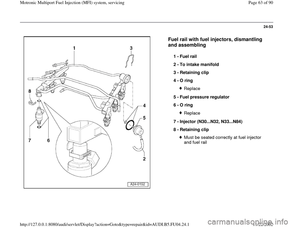
Fuel rail with fuel injectors, dismantling
and assembling
1 -
Fuel rail
2 -
To intake manifold
3 -
Retaining clip
4 -
O ring
Replace
5 -
Fuel pressure regulator
6 -
O ring Replace
7 -
Injector (N30...N32, N33...N84)
8 -
Retaining clip Must be seated correctly at fuel injector
and fuel rail
Pa
ge 63 of 90 Motronic Multi
port Fuel In
jection
(MFI
) system, servicin
g
11/22/2002 htt
p://127.0.0.1:8080/audi/servlet/Dis
play?action=Goto&t
yp
e=re
pair&id=AUDI.B5.FU04.24.1
Page 64 of 90
24-54
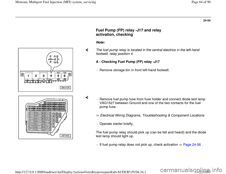
Fuel Pump (FP) relay -J17 and relay
activation, checking
Note:
The fuel pump relay is located in the central electrics in the left-hand
footwell, relay position 4.
A - Checking Fuel Pump (FP) relay -J17
- Remove storage bin in front left-hand footwell.
Electrical Wiring Diagrams, Troubleshooting & Component Locations
The fuel pump relay should pick up (can be felt and heard) and the diode
test lamp should light up. - Remove fuel pump fuse from fuse holder and connect diode test lamp
VAG1527 between Ground and one of the two contacts for the fuel
pump fuse. - Operate starter briefly.
- If fuel pump relay does not pick up, check activation Page 24
-56
.
Pa
ge 64 of 90 Motronic Multi
port Fuel In
jection
(MFI
) system, servicin
g
11/22/2002 htt
p://127.0.0.1:8080/audi/servlet/Dis
play?action=Goto&t
yp
e=re
pair&id=AUDI.B5.FU04.24.1
Page 65 of 90
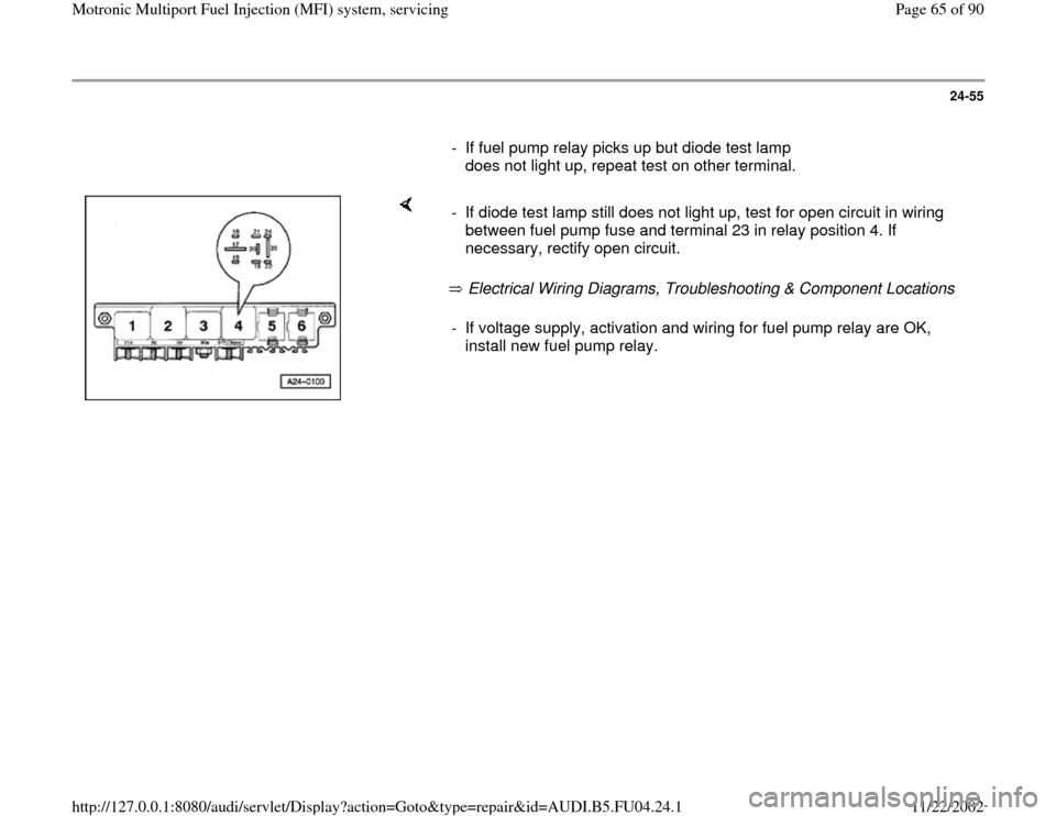
24-55
- If fuel pump relay picks up but diode test lamp
does not light up, repeat test on other terminal.
Electrical Wiring Diagrams, Troubleshooting & Component Locations - If diode test lamp still does not light up, test for open circuit in wiring
between fuel pump fuse and terminal 23 in relay position 4. If
necessary, rectify open circuit. - If voltage supply, activation and wiring for fuel pump relay are OK,
install new fuel pump relay.
Pa
ge 65 of 90 Motronic Multi
port Fuel In
jection
(MFI
) system, servicin
g
11/22/2002 htt
p://127.0.0.1:8080/audi/servlet/Dis
play?action=Goto&t
yp
e=re
pair&id=AUDI.B5.FU04.24.1
Page 66 of 90
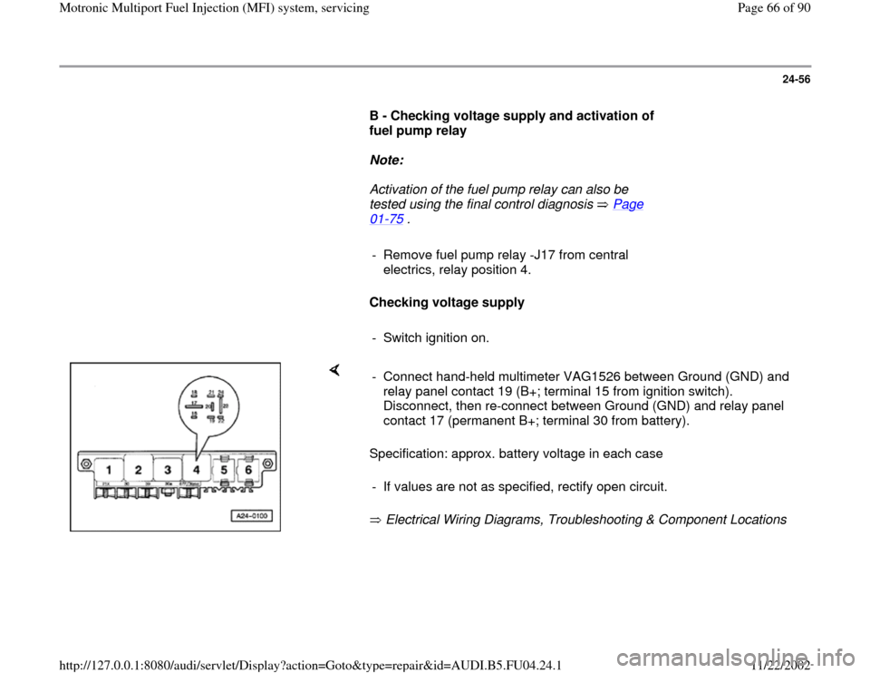
24-56
B - Checking voltage supply and activation of
fuel pump relay
Note:
Activation of the fuel pump relay can also be
tested using the final control diagnosis Page
01
-75
.
- Remove fuel pump relay -J17 from central
electrics, relay position 4.
Checking voltage supply
- Switch ignition on.
Specification: approx. battery voltage in each case
Electrical Wiring Diagrams, Troubleshooting & Component Locations - Connect hand-held multimeter VAG1526 between Ground (GND) and
relay panel contact 19 (B+; terminal 15 from ignition switch).
Disconnect, then re-connect between Ground (GND) and relay panel
contact 17 (permanent B+; terminal 30 from battery).
- If values are not as specified, rectify open circuit.
Pa
ge 66 of 90 Motronic Multi
port Fuel In
jection
(MFI
) system, servicin
g
11/22/2002 htt
p://127.0.0.1:8080/audi/servlet/Dis
play?action=Goto&t
yp
e=re
pair&id=AUDI.B5.FU04.24.1
Page 67 of 90
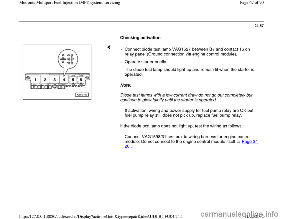
24-57
Checking activation
Note:
Diode test lamps with a low current draw do not go out completely but
continue to glow faintly until the starter is operated.
If the diode test lamp does not light up, test the wiring as follows: - Connect diode test lamp VAG1527 between B+ and contact 16 on
relay panel (Ground connection via engine control module).
- Operate starter briefly.
- The diode test lamp should light up and remain lit when the starter is
operated.
- If activation, wiring and power supply for fuel pump relay are OK but
fuel pump relay still does not pick up, replace fuel pump relay.
- Connect VAG1598/31 test box to wiring harness for engine control
module. Do not connect to the engine control module itself Page 24
-
20
.
Pa
ge 67 of 90 Motronic Multi
port Fuel In
jection
(MFI
) system, servicin
g
11/22/2002 htt
p://127.0.0.1:8080/audi/servlet/Dis
play?action=Goto&t
yp
e=re
pair&id=AUDI.B5.FU04.24.1
Page 68 of 90
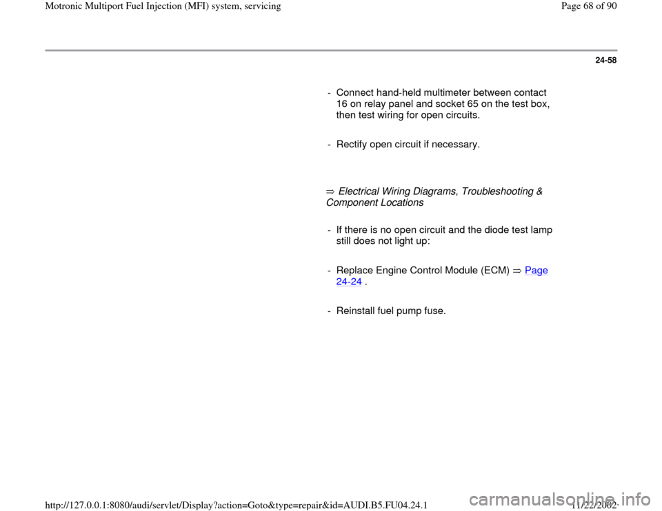
24-58
- Connect hand-held multimeter between contact
16 on relay panel and socket 65 on the test box,
then test wiring for open circuits.
- Rectify open circuit if necessary.
Electrical Wiring Diagrams, Troubleshooting &
Component Locations
- If there is no open circuit and the diode test lamp
still does not light up:
- Replace Engine Control Module (ECM) Page
24
-24
.
- Reinstall fuel pump fuse.
Pa
ge 68 of 90 Motronic Multi
port Fuel In
jection
(MFI
) system, servicin
g
11/22/2002 htt
p://127.0.0.1:8080/audi/servlet/Dis
play?action=Goto&t
yp
e=re
pair&id=AUDI.B5.FU04.24.1
Page 69 of 90
24-59
Mass Air FLow (MAF) sensor -G70,
checking
Requirements
Coolant temperature at least 80 C (175 F)
Electrical consumers switched off (radiator
fan must not run during test)
A/C switched off
Fuse for mass air flow sensor OK
Electrical Wiring Diagrams, Troubleshooting &
Component Locations
Checking function
- Connect vehicle diagnostic, testing and
information system VAS5051 or VAG1551 scan
tool and select engine electronics control
module by entering address word "01" Page
01
-9 . When doing this the engine must be at
idle.
Pa
ge 69 of 90 Motronic Multi
port Fuel In
jection
(MFI
) system, servicin
g
11/22/2002 htt
p://127.0.0.1:8080/audi/servlet/Dis
play?action=Goto&t
yp
e=re
pair&id=AUDI.B5.FU04.24.1
Page 70 of 90
24-60
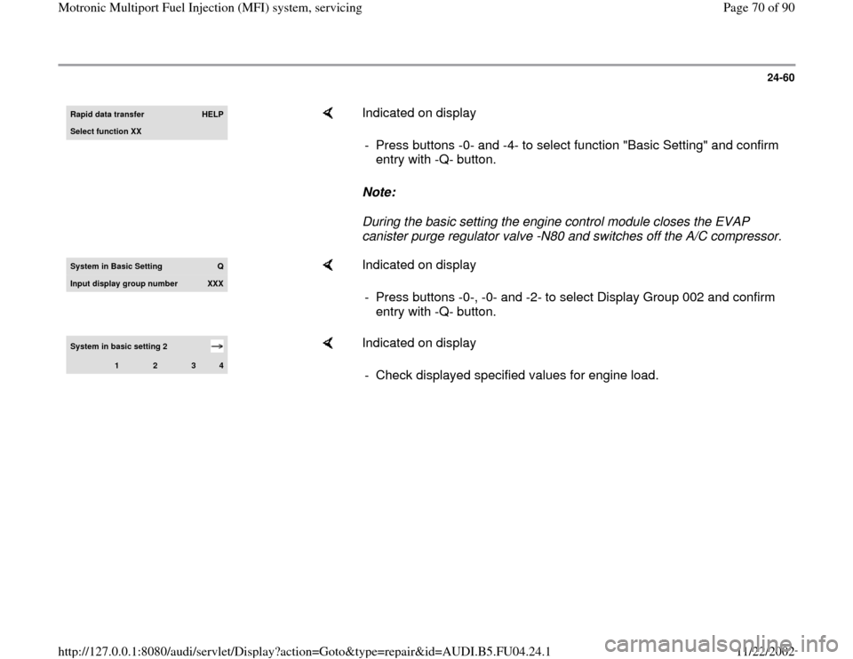
Rapid data transfer
HELP
Select function XX
Indicated on display
Note:
During the basic setting the engine control module closes the EVAP
canister purge regulator valve -N80 and switches off the A/C compressor. - Press buttons -0- and -4- to select function "Basic Setting" and confirm
entry with -Q- button.
System in Basic Settin
g
Q
Input displa
y group number
XXX
Indicated on display
- Press buttons -0-, -0- and -2- to select Display Group 002 and confirm
entry with -Q- button.
System in basic setting 2
1
2
3
4
Indicated on display
- Check displayed specified values for engine load.
Pa
ge 70 of 90 Motronic Multi
port Fuel In
jection
(MFI
) system, servicin
g
11/22/2002 htt
p://127.0.0.1:8080/audi/servlet/Dis
play?action=Goto&t
yp
e=re
pair&id=AUDI.B5.FU04.24.1