AUDI A4 1998 B5 / 1.G APB Engine Motronic Multiport Fuel Injection System Servising Owner's Manual
Manufacturer: AUDI, Model Year: 1998, Model line: A4, Model: AUDI A4 1998 B5 / 1.GPages: 90, PDF Size: 0.84 MB
Page 21 of 90
24-19
WARNING!
Fire hazard! DO NOT smoke or work near
heaters of have anything in the area that can
ignite fuel. The fuel system is pressurized.
Before loosening hose connections or opening
the test connection), place a cloth around the
connection.
Install intake manifold in reverse order. (Tightening
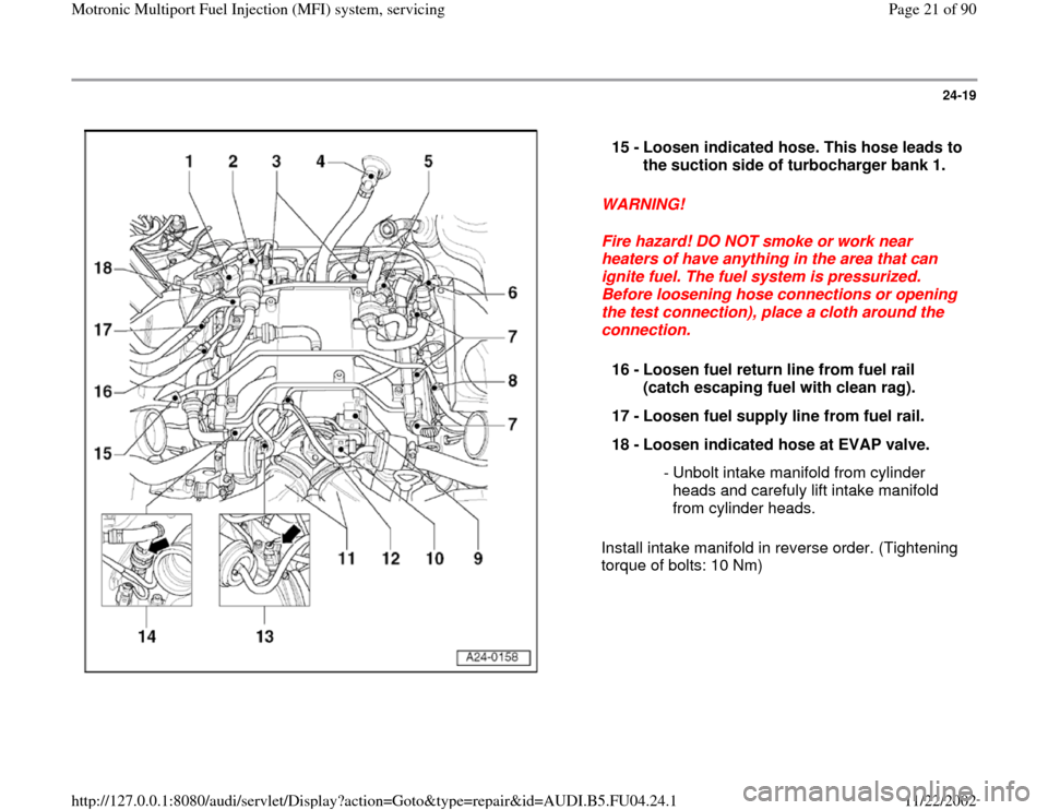
torque of bolts: 10 Nm) 15 -
Loosen indicated hose. This hose leads to
the suction side of turbocharger bank 1.
16 -
Loosen fuel return line from fuel rail
(catch escaping fuel with clean rag).
17 -
Loosen fuel supply line from fuel rail.
18 -
Loosen indicated hose at EVAP valve.
- Unbolt intake manifold from cylinder
heads and carefuly lift intake manifold
from cylinder heads.
Pa
ge 21 of 90 Motronic Multi
port Fuel In
jection
(MFI
) system, servicin
g
11/22/2002 htt
p://127.0.0.1:8080/audi/servlet/Dis
play?action=Goto&t
yp
e=re
pair&id=AUDI.B5.FU04.24.1
Page 22 of 90
24-20
Wiring and component check with
VAG1598/31 test box
Notes:
The VAG1598/31 test box is designed so it can
be simultaneously connected to the control
module wiring harness and to the control
module itself.
This has the advantage of enabling the engine
management system to remain fully operational
even with the test box connected (for example,
when testing signals while the engine is
running).
The instructions for performing the individual
tests indicate whether or not the engine control
module itself also needs to be connected to the
test box.
Use the hand multimeter Fluke 83 (or
equivalent) or the multimeter VAG1715 and the
diode test lamp VAG1527 for the checks.
To connect the testers to VAG1598/31 test box,
always use the adapter leads from VAG1594 A
connector test kit.
Required special tools and test equipment
Pa
ge 22 of 90 Motronic Multi
port Fuel In
jection
(MFI
) system, servicin
g
11/22/2002 htt
p://127.0.0.1:8080/audi/servlet/Dis
play?action=Goto&t
yp
e=re
pair&id=AUDI.B5.FU04.24.1
Page 23 of 90
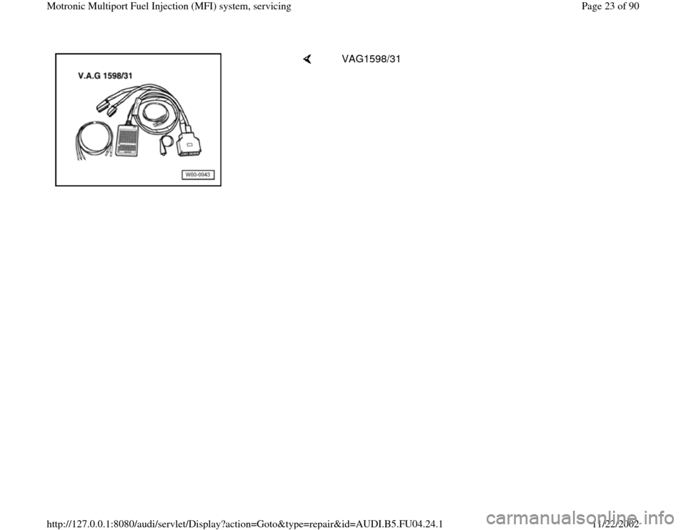
VAG1598/31
Pa
ge 23 of 90 Motronic Multi
port Fuel In
jection
(MFI
) system, servicin
g
11/22/2002 htt
p://127.0.0.1:8080/audi/servlet/Dis
play?action=Goto&t
yp
e=re
pair&id=AUDI.B5.FU04.24.1
Page 24 of 90
24-21
Work sequence
- Switch off ignition.
- Pull rubber gasket forward.
- Remove plenum cover forward.
- Remove cover for E-box (in plenum chamber).
CAUTION!
To prevent damage to the electronic components, switch to the
respective measuring range before connecting the measuring cable
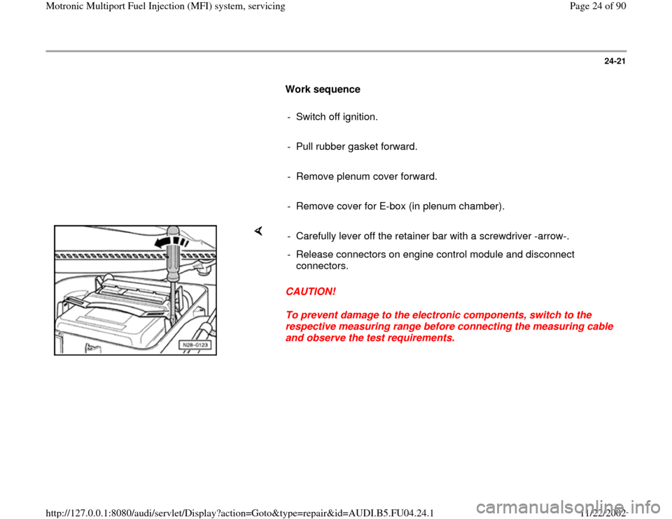
and observe the test requirements. - Carefully lever off the retainer bar with a screwdriver -arrow-.
- Release connectors on engine control module and disconnect
connectors.
Pa
ge 24 of 90 Motronic Multi
port Fuel In
jection
(MFI
) system, servicin
g
11/22/2002 htt
p://127.0.0.1:8080/audi/servlet/Dis
play?action=Goto&t
yp
e=re
pair&id=AUDI.B5.FU04.24.1
Page 25 of 90
24-22
After installing the engine control module, carry out the following
operation
Note:
At the first learning (adaptation) phase during the "Engine-Basic Setting"
the engine might run a little rough at idle and bucks/jerks a little while
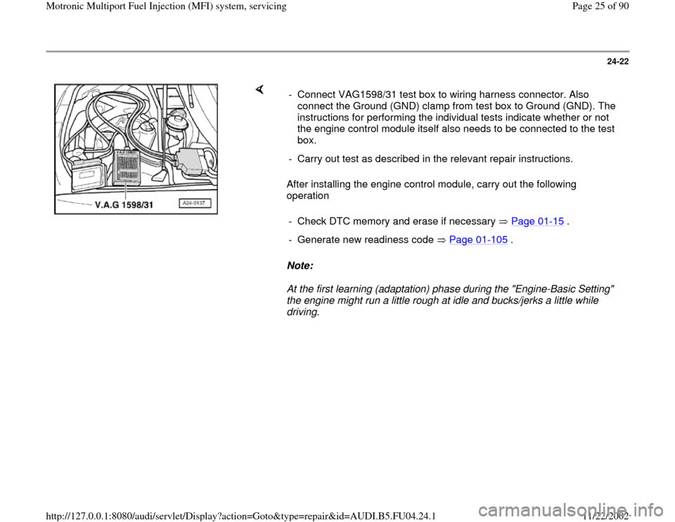
driving. - Connect VAG1598/31 test box to wiring harness connector. Also
connect the Ground (GND) clamp from test box to Ground (GND). The
instructions for performing the individual tests indicate whether or not
the engine control module itself also needs to be connected to the test
box.
- Carry out test as described in the relevant repair instructions.
- Check DTC memory and erase if necessary Page 01
-15
.
- Generate new readiness code Page 01
-105
.
Pa
ge 25 of 90 Motronic Multi
port Fuel In
jection
(MFI
) system, servicin
g
11/22/2002 htt
p://127.0.0.1:8080/audi/servlet/Dis
play?action=Goto&t
yp
e=re
pair&id=AUDI.B5.FU04.24.1
Page 26 of 90
24-23
Procedure after interrupting voltage
supply
Note:
At the first learning (adaptation) phase during the
"Engine-Basic Setting" the engine might run a
little rough at idle and bucks/jerks a little while
driving.
Required special tools and test equipment
Work procedure
Carry out the following work after the voltage was interrupted:
VAS 5051 with VAS 5051/1
orVAG1551 with VAG1551/3B
- Check DTC memory and erase if necessary Page 01
-15
.
- Generate new readiness code Page 01
-105
.
Pa
ge 26 of 90 Motronic Multi
port Fuel In
jection
(MFI
) system, servicin
g
11/22/2002 htt
p://127.0.0.1:8080/audi/servlet/Dis
play?action=Goto&t
yp
e=re
pair&id=AUDI.B5.FU04.24.1
Page 27 of 90
24-24
Motronic Engine Control Module (ECM) -
J220, replacing
Note:
When the engine control module is disconnected
the learned values are erased but the contents of
the DTC memory remain intact.
Required special tools and test equipment
Removing
VAS 5051 with VAS 5051/1
orVAG1551 with VAG1551/3B
- Connect vehicle Diagnostic, Test and Information System VAS5051 or
VAG1551 scan tool to vehicle and select control module for engine
elcectronics "Adress word" 01 Page 01
-9 . The ignition must be
switched on.
8D0907551.. 2.7L V6/5VT
G 0002
Codin
g 06711
WSC 06388
Indicated on display: e.g. ECM identification on VAG1551
- Always display control module identification and print out Page 01
-
13
.
Pa
ge 27 of 90 Motronic Multi
port Fuel In
jection
(MFI
) system, servicin
g
11/22/2002 htt
p://127.0.0.1:8080/audi/servlet/Dis
play?action=Goto&t
yp
e=re
pair&id=AUDI.B5.FU04.24.1
Page 28 of 90
24-25
- Compare coding with coding variation table
Page 01
-93
.
- Switch ignition off.
- Pull rubber gasket forward.
- Remove plenum cover forward.
- Remove cover for E-box (in plenum chamber).
Installing
Installation is performed in the reverse sequence. However note the
following:
Note:
At the first learning (adaptation) phase during the "Engine-Basic Setting"
the engine might run a little rough at idle and bucks/jerks a little while
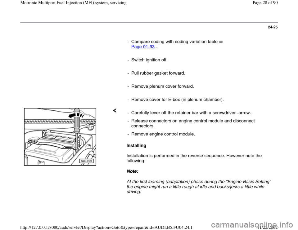
driving. - Carefully lever off the retainer bar with a screwdriver -arrow-.
- Release connectors on engine control module and disconnect
connectors.
- Remove engine control module.
Pa
ge 28 of 90 Motronic Multi
port Fuel In
jection
(MFI
) system, servicin
g
11/22/2002 htt
p://127.0.0.1:8080/audi/servlet/Dis
play?action=Goto&t
yp
e=re
pair&id=AUDI.B5.FU04.24.1
Page 29 of 90
24-26
Important Note:
After installing new engine control module, carry
out the following operations:
- Check DTC memory and erase if necessary
Page 01
-15
.
- Perform adaptation of Throttle Valve Control
Module -J338 Page 24
-146
.
- Observe notes for coding new engine control
module Page 01
-93
.
- On vehicles with cruise control (recognizable at
steering column switch), activate cruise control
function in the engine control module.
Repair Manual, Electrical Equipment, Repair
Group 01
- On vehicles with automatic transmission carry
out adaptation for Kick-Down switch Page 24
-
166
.
- Generate readiness code Page 01
-105
.
- Perform adaptation of immobilizer to engine
control module
Pa
ge 29 of 90 Motronic Multi
port Fuel In
jection
(MFI
) system, servicin
g
11/22/2002 htt
p://127.0.0.1:8080/audi/servlet/Dis
play?action=Goto&t
yp
e=re
pair&id=AUDI.B5.FU04.24.1
Page 30 of 90
Repair Manual, Electrical Equipment, Repair
Group 01, On Board Diagnostic of Immobilizer, Adaptation after replacing engine control module
Pa
ge 30 of 90 Motronic Multi
port Fuel In
jection
(MFI
) system, servicin
g
11/22/2002 htt
p://127.0.0.1:8080/audi/servlet/Dis
play?action=Goto&t
yp
e=re
pair&id=AUDI.B5.FU04.24.1