AUDI A4 1998 B5 / 1.G AWM Engine Charge Air Syst
Manufacturer: AUDI, Model Year: 1998,
Model line: A4,
Model: AUDI A4 1998 B5 / 1.G
Pages: 17, PDF Size: 0.23 MB
AUDI A4 1998 B5 / 1.G AWM Engine Charge Air Syst
A4 1998 B5 / 1.G
AUDI
AUDI
https://www.carmanualsonline.info/img/6/936/w960_936-0.png
AUDI A4 1998 B5 / 1.G AWM Engine Charge Air Syst
Trending: ignition, seat memory, brake light, wheel, ECU, check engine, fuel pump
Page 1 of 17
21-1
Charge air system with
turbocharger, checking
Notes:
For cleanliness rules, see Page 21
-44
.
Secure all hose connections with the correct
hose clips (same as original equipment):
Parts Catalog
Before performing a check or repair, all hoses
and lines must be checked for tight seating and
leaks.
Always replace seals, gaskets and self-locking
nuts.
Pa
ge 1 of 17 Char
ge air s
ystem with turbochar
ger, checkin
g
11/21/2002 htt
p://127.0.0.1:8080/audi/servlet/Dis
play?action=Goto&t
yp
e=re
pair&id=AUDI.B5.GE06.21.1
Page 2 of 17
21-2
Safety precautions
Note the following points if testers and measuring
instruments have to be used during a road test:
WARNING!
Always attach testers and measuring
instruments to the back seat and have a
second person operate them from there.
If test equipment were operated from the
front passenger seat, the person sitting there
could be injured if the front passenger airbag
were triggered in the event of an accident.
Pa
ge 2 of 17 Char
ge air s
ystem with turbochar
ger, checkin
g
11/21/2002 htt
p://127.0.0.1:8080/audi/servlet/Dis
play?action=Goto&t
yp
e=re
pair&id=AUDI.B5.GE06.21.1
Page 3 of 17
21-3
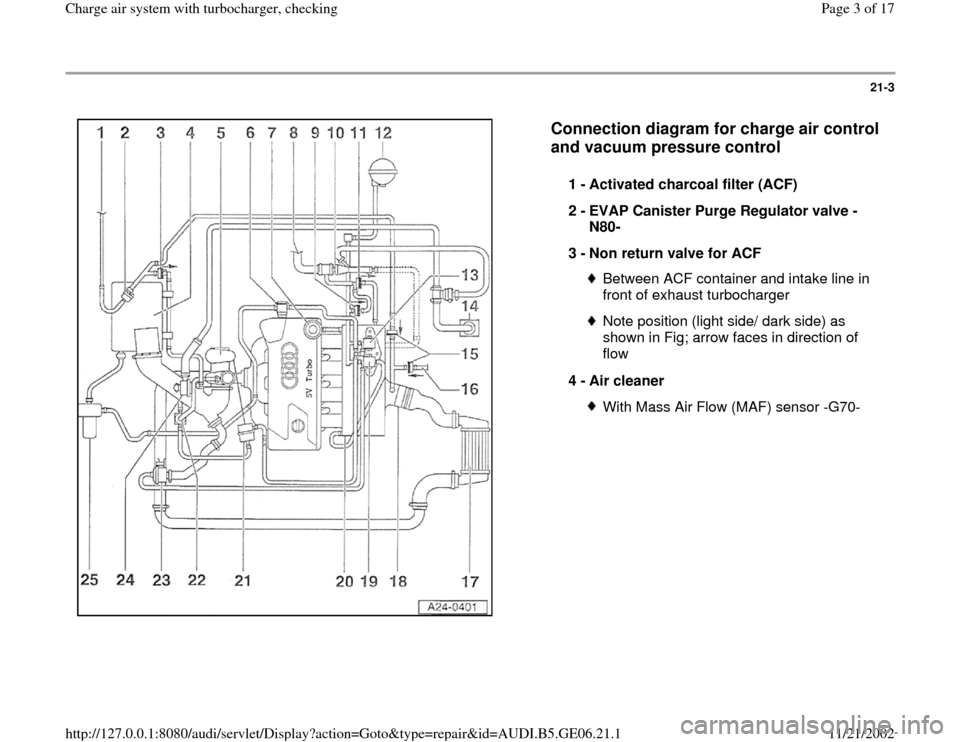
Connection diagram for charge air control
and vacuum pressure control
1 -
Activated charcoal filter (ACF)
2 -
EVAP Canister Purge Regulator valve -
N80-
3 -
Non return valve for ACF
Between ACF container and intake line in
front of exhaust turbocharger Note position (light side/ dark side) as
shown in Fig; arrow faces in direction of
flow
4 -
Air cleaner With Mass Air Flow (MAF) sensor -G70-
Pa
ge 3 of 17 Char
ge air s
ystem with turbochar
ger, checkin
g
11/21/2002 htt
p://127.0.0.1:8080/audi/servlet/Dis
play?action=Goto&t
yp
e=re
pair&id=AUDI.B5.GE06.21.1
Page 4 of 17
21-4
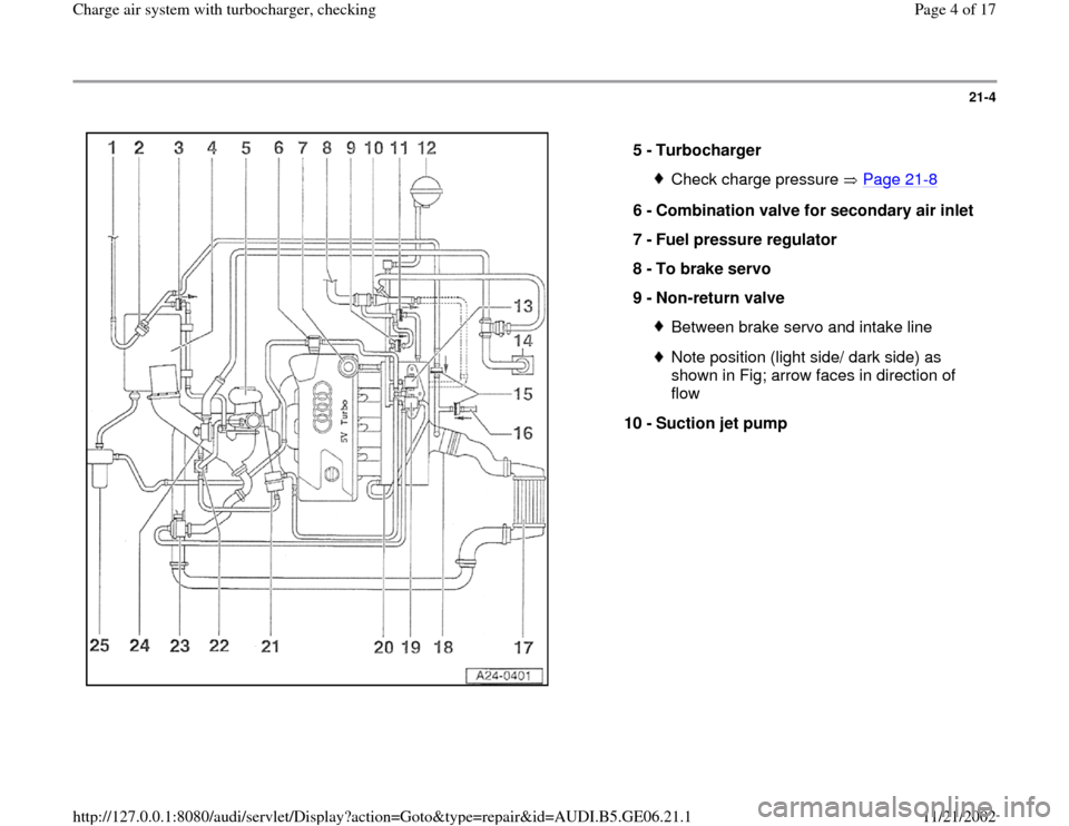
5 -
Turbocharger
Check charge pressure Page 21
-8
6 -
Combination valve for secondary air inlet
7 -
Fuel pressure regulator
8 -
To brake servo
9 -
Non-return valve
Between brake servo and intake lineNote position (light side/ dark side) as
shown in Fig; arrow faces in direction of
flow
10 -
Suction jet pump
Pa
ge 4 of 17 Char
ge air s
ystem with turbochar
ger, checkin
g
11/21/2002 htt
p://127.0.0.1:8080/audi/servlet/Dis
play?action=Goto&t
yp
e=re
pair&id=AUDI.B5.GE06.21.1
Page 5 of 17
21-5
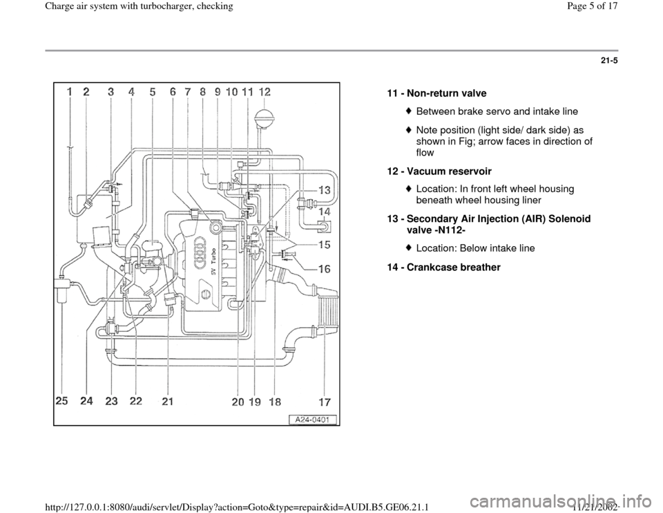
11 -
Non-return valve
Between brake servo and intake lineNote position (light side/ dark side) as
shown in Fig; arrow faces in direction of
flow
12 -
Vacuum reservoir Location: In front left wheel housing
beneath wheel housing liner
13 -
Secondary Air Injection (AIR) Solenoid
valve -N112- Location: Below intake line
14 -
Crankcase breather
Pa
ge 5 of 17 Char
ge air s
ystem with turbochar
ger, checkin
g
11/21/2002 htt
p://127.0.0.1:8080/audi/servlet/Dis
play?action=Goto&t
yp
e=re
pair&id=AUDI.B5.GE06.21.1
Page 6 of 17
21-6
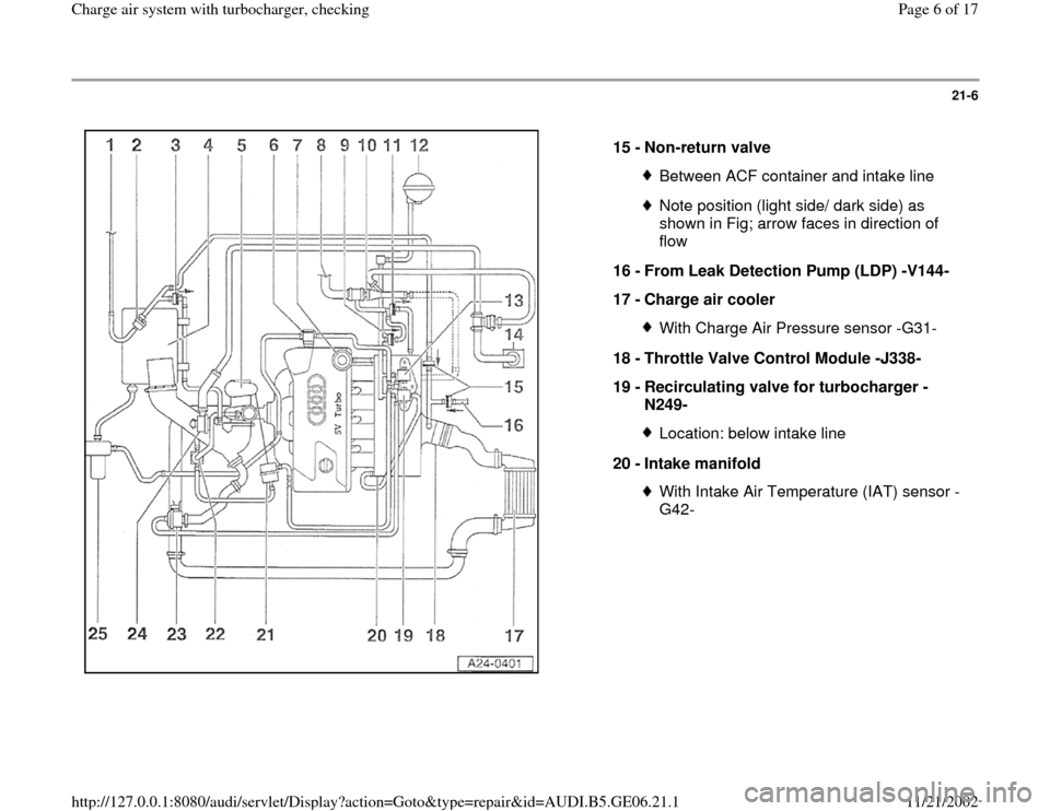
15 -
Non-return valve
Between ACF container and intake lineNote position (light side/ dark side) as
shown in Fig; arrow faces in direction of
flow
16 -
From Leak Detection Pump (LDP) -V144-
17 -
Charge air cooler With Charge Air Pressure sensor -G31-
18 -
Throttle Valve Control Module -J338-
19 -
Recirculating valve for turbocharger -
N249- Location: below intake line
20 -
Intake manifold With Intake Air Temperature (IAT) sensor -
G42-
Pa
ge 6 of 17 Char
ge air s
ystem with turbochar
ger, checkin
g
11/21/2002 htt
p://127.0.0.1:8080/audi/servlet/Dis
play?action=Goto&t
yp
e=re
pair&id=AUDI.B5.GE06.21.1
Page 7 of 17
21-7
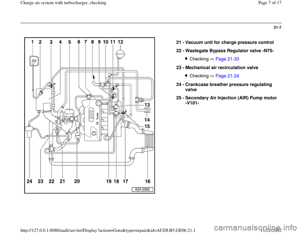
21 -
Vacuum unit for charge pressure control
22 -
Wastegate Bypass Regulator valve -N75-
Checking Page 21
-33
23 -
Mechanical air recirculation valve
Checking Page 21
-24
24 -
Crankcase breather pressure regulating
valve
25 -
Secondary Air Injection (AIR) Pump motor
-V101-
Pa
ge 7 of 17 Char
ge air s
ystem with turbochar
ger, checkin
g
11/21/2002 htt
p://127.0.0.1:8080/audi/servlet/Dis
play?action=Goto&t
yp
e=re
pair&id=AUDI.B5.GE06.21.1
Page 8 of 17
21-8
Turbocharger and charge pressure
regulating valve, checking
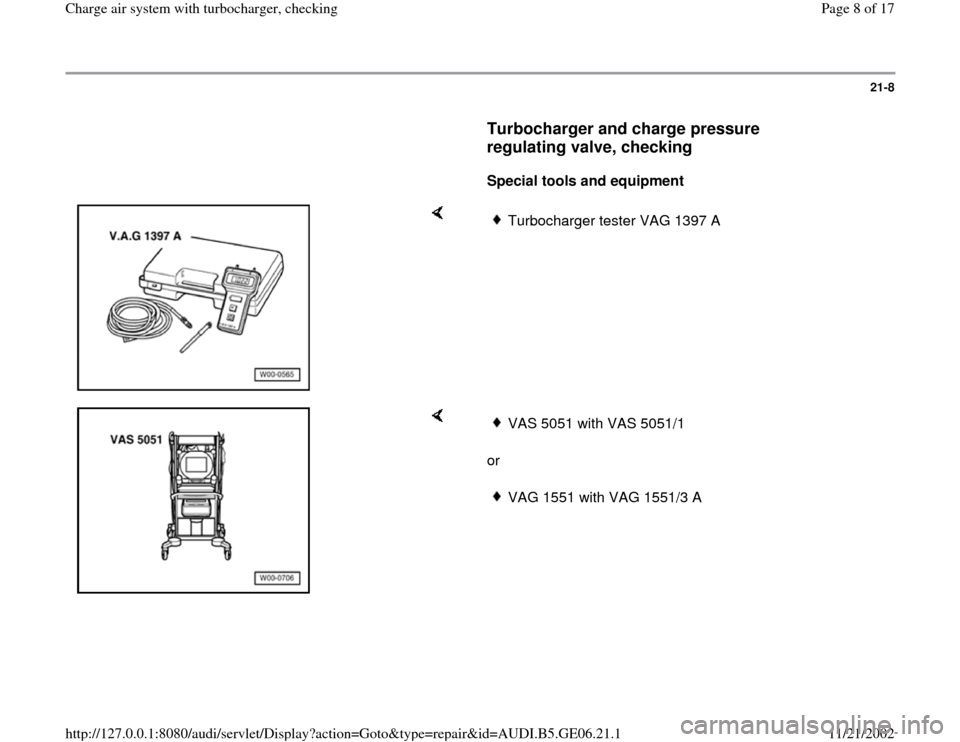
Special tools and equipment
Turbocharger tester VAG 1397 A
or
VAS 5051 with VAS 5051/1VAG 1551 with VAG 1551/3 A
Pa
ge 8 of 17 Char
ge air s
ystem with turbochar
ger, checkin
g
11/21/2002 htt
p://127.0.0.1:8080/audi/servlet/Dis
play?action=Goto&t
yp
e=re
pair&id=AUDI.B5.GE06.21.1
Page 9 of 17
21-9
Test requirements:
Vehicle diagnostic, testing and information
system VAS 5051 or VAG 1551 Scan Tool
connected.
Repair Manual, 1.8 Liter 4
-Cyl. 5V Turbo Fuel
Injection & Ignition, Engine Code(s): AWM, Repair Group 01
All hoses and lines must be checked for
correct seating and leaks.
Diagnostic Trouble Code (DTC) memory has
been checked:
Repair Manual, 1.8 Liter 4
-Cyl. 5V Turbo Fuel
Injection & Ignition, Engine Code(s): AWM, Repair Group 01
Output Diagnostic Test Mode (DTM) has
been performed:
Repair Manual, 1.8 Liter 4
-Cyl. 5V Turbo Fuel
Injection & Ignition, Engine Code(s): AWM,
Pa
ge 9 of 17 Char
ge air s
ystem with turbochar
ger, checkin
g
11/21/2002 htt
p://127.0.0.1:8080/audi/servlet/Dis
play?action=Goto&t
yp
e=re
pair&id=AUDI.B5.GE06.21.1
Page 10 of 17
Repair Group 01
Test sequence
WARNING!
Always attach testers and measuring
instruments to the back seat and have a
second person operate them from there.
If test equipment were operated from the
front passenger seat, the person sitting there
could be injured if the front passenger airbag
were triggered in the event of an accident.
Pa
ge 10 of 17 Char
ge air s
ystem with turbochar
ger, checkin
g
11/21/2002 htt
p://127.0.0.1:8080/audi/servlet/Dis
play?action=Goto&t
yp
e=re
pair&id=AUDI.B5.GE06.21.1
Trending: wheel, fuel pressure, key battery, battery, fuel, display, warning
