AUDI A4 1999 B5 / 1.G 01W Transmission Differential Remove And Install Workshop Manual
Manufacturer: AUDI, Model Year: 1999, Model line: A4, Model: AUDI A4 1999 B5 / 1.GPages: 6, PDF Size: 0.2 MB
Page 1 of 6
39-10
Differential, removing and
installing
Special tools and equipment
VW771 slide hammer - complete set
3257 Puller
Kukko 21/3 extractor
Notes:
Removal and installation is also possible with
transmission installed.
The differential can be removed and installed
without disassembling shift mechanism, input
shaft, pinion shaft or transmission cover. The
above components have to be disassembled if
the differential needs to be adjusted.
Flanges with and without polygon bearings are
used. Application Page 00
-3 .
Polygon bearings can only be replaced together
with drive flange.
Pa
ge 1 of 6 Differential, removin
g and installin
g
11/19/2002 htt
p://127.0.0.1:8080/audi/servlet/Dis
play?action=Goto&t
yp
e=re
pair&id=AUDI.B5.TM01.39.3
Page 2 of 6
Look for visible damage to polygon bearings.
The rough operation of the polygon bearing with
the drive flange not installed is not an indication
that the bearings are malfunctioning. An
acoustic check can only be carried out while
installed.
A spacer ring is installed between the polygon
bearing and differential pinion for drive flanges
with a spline diameter of 30 mm Page 39
-
14
, Fig. 3
and Fig. 4
.
Adjustments are required when replacing
components marked with 1): Page 39
-33
,
list of adjustments
Pa
ge 2 of 6 Differential, removin
g and installin
g
11/19/2002 htt
p://127.0.0.1:8080/audi/servlet/Dis
play?action=Goto&t
yp
e=re
pair&id=AUDI.B5.TM01.39.3
Page 3 of 6
39-11
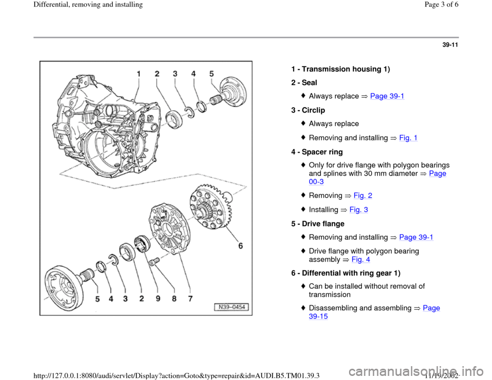
1 -
Transmission housing 1)
2 -
Seal
Always replace Page 39
-1
3 -
Circlip
Always replaceRemoving and installing Fig. 1
4 -
Spacer ring
Only for drive flange with polygon bearings
and splines with 30 mm diameter Page 00
-3
Removing Fig. 2Installing Fig. 3
5 -
Drive flange
Removing and installing Page 39
-1
Drive flange with polygon bearing
assembly Fig. 4
6 -
Differential with ring gear 1)
Can be installed without removal of
transmission Disassembling and assembling Page 39
-15
Pa
ge 3 of 6 Differential, removin
g and installin
g
11/19/2002 htt
p://127.0.0.1:8080/audi/servlet/Dis
play?action=Goto&t
yp
e=re
pair&id=AUDI.B5.TM01.39.3
Page 4 of 6
39-12
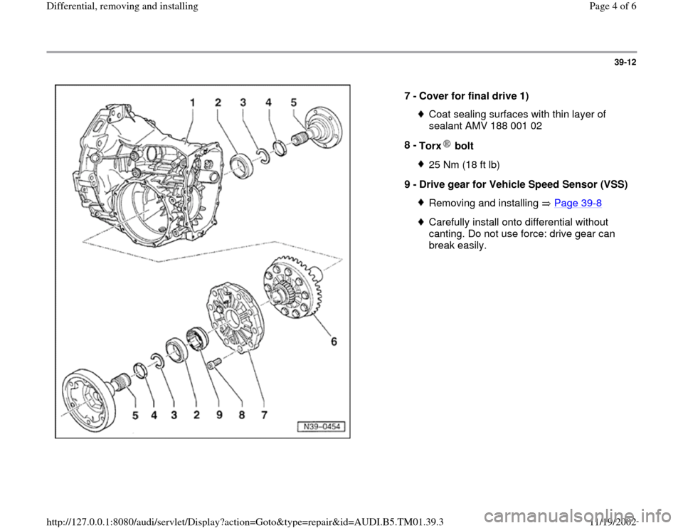
7 -
Cover for final drive 1)
Coat sealing surfaces with thin layer of
sealant AMV 188 001 02
8 -
Torx bolt 25 Nm (18 ft lb)
9 -
Drive gear for Vehicle Speed Sensor (VSS)Removing and installing Page 39
-8
Carefully install onto differential without
canting. Do not use force: drive gear can
break easily.
Pa
ge 4 of 6 Differential, removin
g and installin
g
11/19/2002 htt
p://127.0.0.1:8080/audi/servlet/Dis
play?action=Goto&t
yp
e=re
pair&id=AUDI.B5.TM01.39.3
Page 5 of 6
39-13
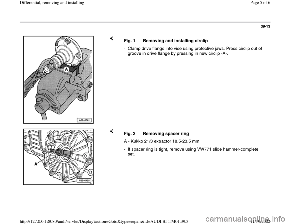
Fig. 1 Removing and installing circlip
- Clamp drive flange into vise using protective jaws. Press circlip out of
groove in drive flange by pressing in new circlip -A-.
Fig. 2 Removing spacer ring
A - Kukko 21/3 extractor 18.5-23.5 mm
- If spacer ring is tight, remove using VW771 slide hammer-complete
set.
Pa
ge 5 of 6 Differential, removin
g and installin
g
11/19/2002 htt
p://127.0.0.1:8080/audi/servlet/Dis
play?action=Goto&t
yp
e=re
pair&id=AUDI.B5.TM01.39.3
Page 6 of 6
39-14
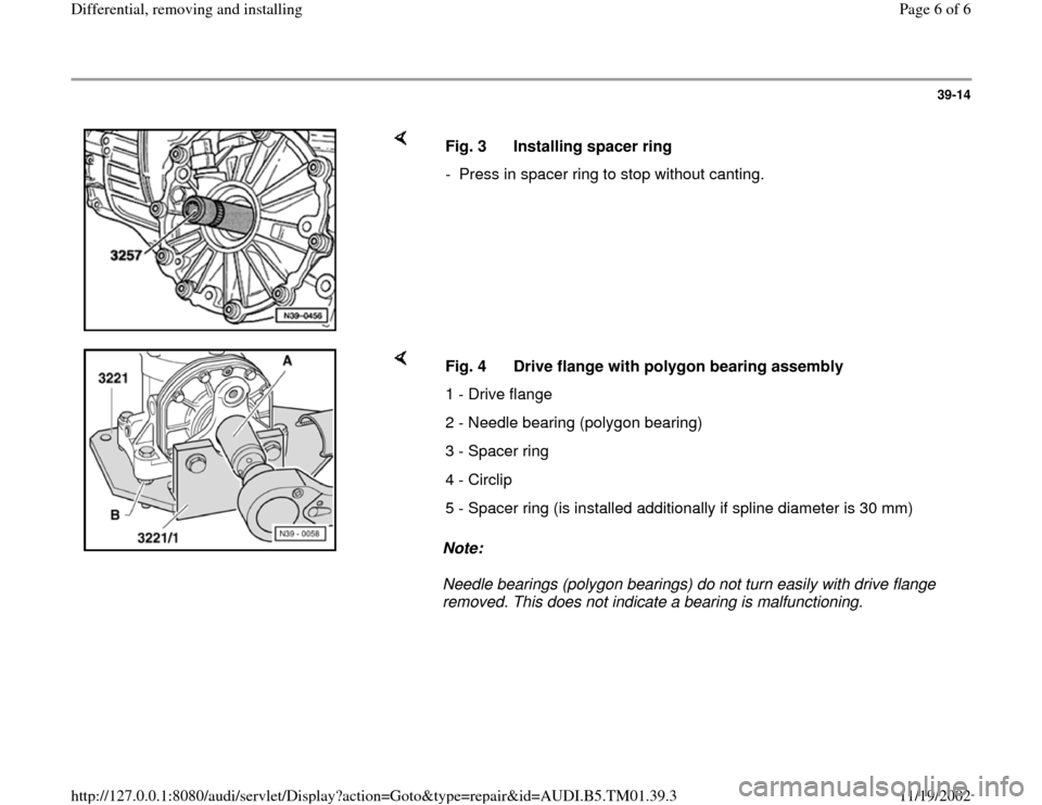
Fig. 3 Installing spacer ring
- Press in spacer ring to stop without canting.
Note:
Needle bearings (polygon bearings) do not turn easily with drive flange
removed. This does not indicate a bearing is malfunctioning. Fig. 4 Drive flange with polygon bearing assembly
1 - Drive flange
2 - Needle bearing (polygon bearing)
3 - Spacer ring
4 - Circlip
5 - Spacer ring (is installed additionally if spline diameter is 30 mm)
Pa
ge 6 of 6 Differential, removin
g and installin
g
11/19/2002 htt
p://127.0.0.1:8080/audi/servlet/Dis
play?action=Goto&t
yp
e=re
pair&id=AUDI.B5.TM01.39.3