AUDI A4 1999 B5 / 1.G AFC Engine On Board Diagnostic Multiport Fuel Injection Workshop Manual
Manufacturer: AUDI, Model Year: 1999, Model line: A4, Model: AUDI A4 1999 B5 / 1.GPages: 366, PDF Size: 1.21 MB
Page 271 of 366
01-193
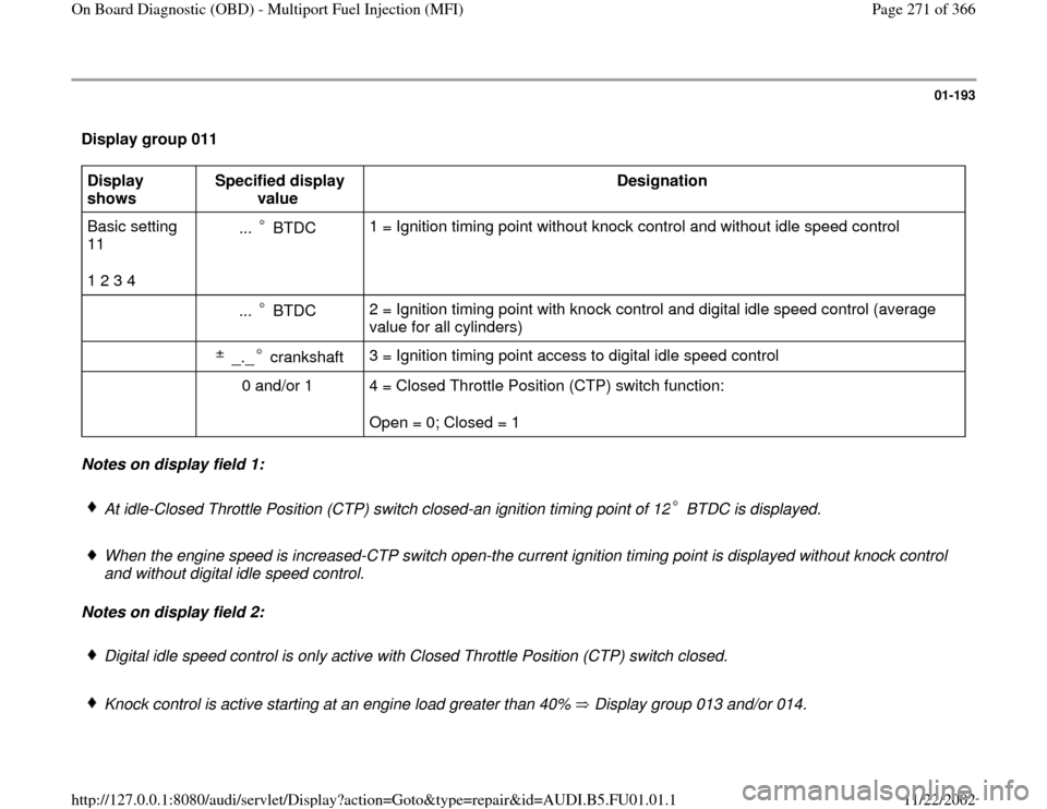
Display group 011 Display
shows Specified display
value Designation
Basic setting
11
1 2 3 4 ... BTDC
1 = Ignition timing point without knock control and without idle speed control
... BTDC 2 = Ignition timing point with knock control and digital idle speed control (average
value for all cylinders)
_._ crankshaft 3 = Ignition timing point access to digital idle speed control
0 and/or 1 4 = Closed Throttle Position (CTP) switch function:
Open = 0; Closed = 1
Notes on display field 1:
At idle-Closed Throttle Position (CTP) switch closed-an ignition timing point of 12 BTDC is displayed. When the engine speed is increased-CTP switch open-the current ignition timing point is displayed without knock control
and without digital idle speed control.
Notes on display field 2:
Digital idle speed control is only active with Closed Throttle Position (CTP) switch closed.
Knock control is active starting at an engine load greater than 40% Display group 013 and/or 014.
Pa
ge 271 of 366 On Board Dia
gnostic
(OBD
) - Multi
port Fuel In
jection
(MFI
)
11/22/2002 htt
p://127.0.0.1:8080/audi/servlet/Dis
play?action=Goto&t
yp
e=re
pair&id=AUDI.B5.FU01.01.1
Page 272 of 366
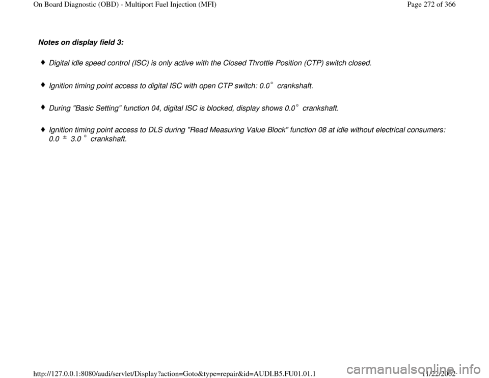
Notes on display field 3:
Digital idle speed control (ISC) is only active with the Closed Throttle Position (CTP) switch closed.
Ignition timing point access to digital ISC with open CTP switch: 0.0 crankshaft. During "Basic Setting" function 04, digital ISC is blocked, display shows 0.0 crankshaft. Ignition timing point access to DLS during "Read Measuring Value Block" function 08 at idle without electrical consumers:
0.0 3.0 crankshaft.
Pa
ge 272 of 366 On Board Dia
gnostic
(OBD
) - Multi
port Fuel In
jection
(MFI
)
11/22/2002 htt
p://127.0.0.1:8080/audi/servlet/Dis
play?action=Goto&t
yp
e=re
pair&id=AUDI.B5.FU01.01.1
Page 273 of 366
01-194
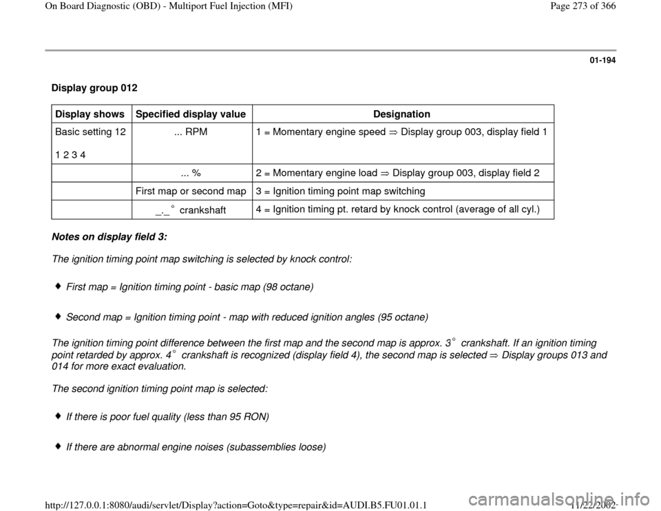
Display group 012 Display shows
Specified display value
Designation
Basic setting 12
1 2 3 4 ... RPM 1 = Momentary engine speed Display group 003, display field 1 ... % 2 = Momentary engine load Display group 003, display field 2 First map or second map 3 = Ignition timing point map switching
_._ crankshaft
4 = Ignition timing pt. retard by knock control (average of all cyl.)
Notes on display field 3:
The ignition timing point map switching is selected by knock control:
First map = Ignition timing point - basic map (98 octane)
Second map = Ignition timing point - map with reduced ignition angles (95 octane)
The ignition timing point difference between the first map and the second map is approx. 3 crankshaft. If an ignition timing
point retarded by approx. 4 crankshaft is recognized (display field 4), the second map is selected Display groups 013 and
014 for more exact evaluation.
The second ignition timing point map is selected:
If there is poor fuel quality (less than 95 RON)
If there are abnormal engine noises (subassemblies loose)
Pa
ge 273 of 366 On Board Dia
gnostic
(OBD
) - Multi
port Fuel In
jection
(MFI
)
11/22/2002 htt
p://127.0.0.1:8080/audi/servlet/Dis
play?action=Goto&t
yp
e=re
pair&id=AUDI.B5.FU01.01.1
Page 274 of 366
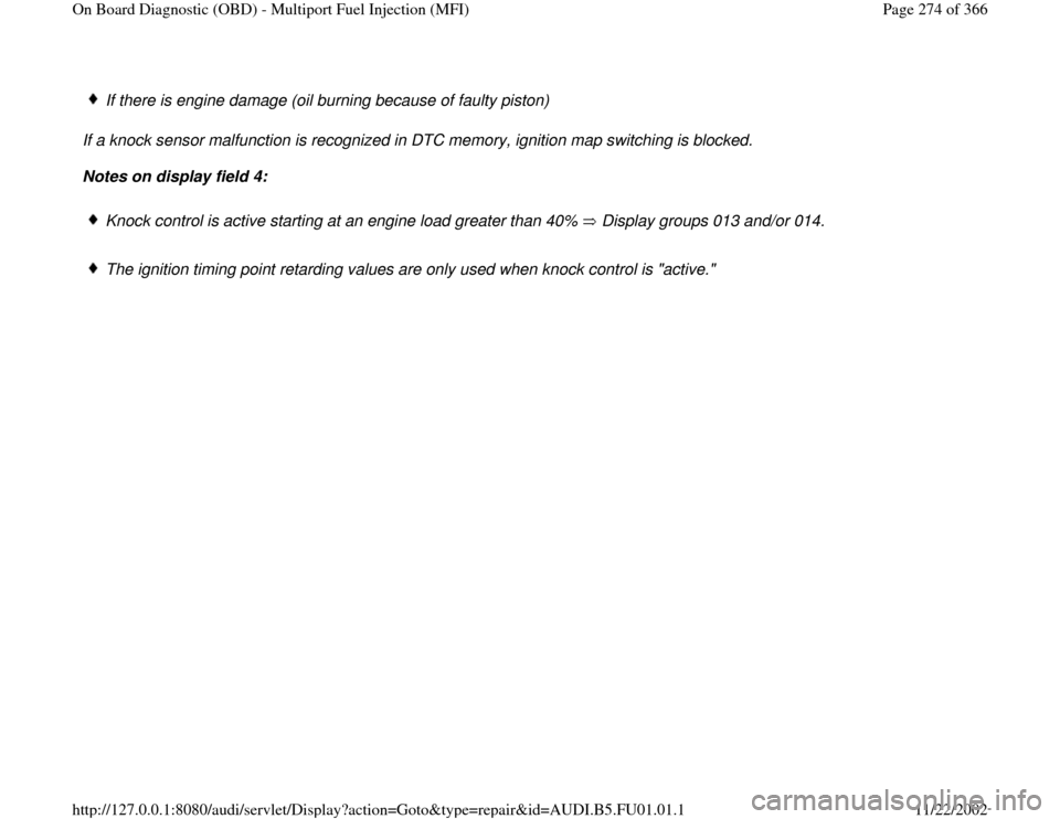
If there is engine damage (oil burning because of faulty piston)
If a knock sensor malfunction is recognized in DTC memory, ignition map switching is blocked.
Notes on display field 4:
Knock control is active starting at an engine load greater than 40% Display groups 013 and/or 014. The ignition timing point retarding values are only used when knock control is "active."
Pa
ge 274 of 366 On Board Dia
gnostic
(OBD
) - Multi
port Fuel In
jection
(MFI
)
11/22/2002 htt
p://127.0.0.1:8080/audi/servlet/Dis
play?action=Goto&t
yp
e=re
pair&id=AUDI.B5.FU01.01.1
Page 275 of 366

01-195
Display group 013 Display shows
Specified display value
Designation
Basic setting 13
1 2 3 4 First map
and/or
second map 1 = Ignition timing point map switching display group 012, display field 3
_._ crankshaft
2 = Ignition timing point retarded by knock control (cylinder 1)
_._ crankshaft 3 = Ignition timing point retarded by knock control (cylinder 2)
_._ crankshaft 4 = Ignition timing point retarded by knock control (cylinder 3)
Display group 014 Display shows
Specified display value
Designation
Basic setting 14
1 2 3 4 First map
and/or
second map 1 = Ignition timing point map switching display group 012, display field 3
_._ crankshaft
2 = Ignition timing point retarded by knock control (cylinder 4)
_._ crankshaft 3 = Ignition timing point retarded by knock control (cylinder 5)
_._ crankshaft 4 = Ignition timing point retarded by knock control (cylinder 6)
Pa
ge 275 of 366 On Board Dia
gnostic
(OBD
) - Multi
port Fuel In
jection
(MFI
)
11/22/2002 htt
p://127.0.0.1:8080/audi/servlet/Dis
play?action=Goto&t
yp
e=re
pair&id=AUDI.B5.FU01.01.1
Page 276 of 366
01-196
Display groups 013 and 014
Notes on display fields 2, 3 and 4:
Knock control is active starting at an engine load greater than 40%. If the engine load exceeds 40%, the current ignition timing
point retarding value is displayed; if the engine load drops below 40%, the last values used are displayed constantly.
If there is audible knocking without recognizable retarding of the ignition timing point, the engine speed should be increased
over 3500 RPM for 5 seconds to initiate the knock sensor malfunction recognition (On Board Diagnostic).
If an ignition timing point retarding value of one cylinder deviates from the others, the following malfunctions are possible:
Loose subassemblies
Corrosion on the harness connector
Engine damage (e.g. oil combustion with faulty piston)
If there are high ignition timing point retarding values on all cylinders of bank 1 or bank 2, the following malfunctions are
possible:
Corrosion on the harness connector display groups 015 and 016 Knock sensor tightening torque, 20 Nm (14 ft lb), not OK
Open circuit display groups 015 and 016 Knock sensor faulty
Pa
ge 276 of 366 On Board Dia
gnostic
(OBD
) - Multi
port Fuel In
jection
(MFI
)
11/22/2002 htt
p://127.0.0.1:8080/audi/servlet/Dis
play?action=Goto&t
yp
e=re
pair&id=AUDI.B5.FU01.01.1
Page 277 of 366
Loose subassemblies
If there are high ignition timing point retarding values on all six cylinders (banks 1 and 2), the car has been filled with fuel
having low octane (less than 98 RON).
Pa
ge 277 of 366 On Board Dia
gnostic
(OBD
) - Multi
port Fuel In
jection
(MFI
)
11/22/2002 htt
p://127.0.0.1:8080/audi/servlet/Dis
play?action=Goto&t
yp
e=re
pair&id=AUDI.B5.FU01.01.1
Page 278 of 366

01-197
Display group 015 Display shows
Specified display value
Designation
Basic setting 15
1 2 3 4 ___ RPM 1 = Momentary engine speed display group 003, display field 1 _._V 2 = Knock sensor signal (cylinder 1)
_._V 3 = Knock sensor signal (cylinder 2)
_._V 4 = Knock sensor signal (cylinder 3) Display group 016 Display shows
Specified display value
Designation
Basic setting 16
1 2 3 4 ___ RPM 1 = Momentary engine speed display group 003, display field 1 _._ V 2 = Knock sensor signal (cylinder 4)
_._ V 3 = Knock sensor signal (cylinder 5)
_._ V 4 = Knock sensor signal (cylinder 6)
Pa
ge 278 of 366 On Board Dia
gnostic
(OBD
) - Multi
port Fuel In
jection
(MFI
)
11/22/2002 htt
p://127.0.0.1:8080/audi/servlet/Dis
play?action=Goto&t
yp
e=re
pair&id=AUDI.B5.FU01.01.1
Page 279 of 366
01-198
Display groups 015 and 016
Notes on display fields 2, 3 and 4:
If there is a difference of more than a factor of 3 between the lowest and the highest knock sensor signal in one display group,
the following malfunction is possible:
Corrosion on the harness connector
If there are differences of more than 50% in knock sensor signal between display group 015 (cylinders 1 to 3) and display
group 016 (cylinders 4 to 6), the following malfunctions are possible:
Corrosion on the harness connector
Open circuit
Knock sensor faulty
If no malfunctions are found during the electrical testing of the knock sensor, the wiring and the connections, the engine
should be checked for loose subassemblies or engine damage (e.g. oil burning due to faulty piston) Display groups 013
and/or 014.
Pa
ge 279 of 366 On Board Dia
gnostic
(OBD
) - Multi
port Fuel In
jection
(MFI
)
11/22/2002 htt
p://127.0.0.1:8080/audi/servlet/Dis
play?action=Goto&t
yp
e=re
pair&id=AUDI.B5.FU01.01.1
Page 280 of 366
01-199
Display group 017
Note:
If in display group 029, display field 1, the value of the EGR system throughput diagnosis is not set to "0" during the
regeneration of the "readiness code," and/or a malfunction relating to the exhaust system is stored in the DTC memory,
display group 017 is used to carry out a selective diagnosis.
During cold start at idle, -10 C to 30 C (14 to 86 F), and during "Basic Setting" function 04, no exhaust gas recirculation
takes place. Since exhaust gas recirculation is switched off automatically during "Basic Setting" function 04, diagnosis of EGR
throughput is evaluated only in "Read Measuring Value Block." function 08. If diagnostic conditions are fulfilled, the Engine Control Module (ECM) checks the flow through the EGR system after each
start. The diagnostic conditions are only reached during a trip at 80-100 km/h (50-63 mph) in 4th or 5 gear and/or with selector
lever in the "D"position, preferably in 4th gear position. If the diagnostic conditions are fulfilled, the diagnosis is active. In order
to get a diagnostic result, the vehicle must be driven approx. 1-1/2 to 5 minutes under the diagnostic conditions. However, the
diagnosis is only considered OK when the EGR temperature (display field 4) is greater than 50 C (122 F) during the reading
time (display field 2). Diagnosis of the EGR flow (exhaust gas recirculation quantity) is active as soon as the following diagnostic conditions are
fulfilled:
Coolant temperature: greater than 8 C (46 F) ( display group 001) Vehicle speed: constant drive
Engine speed: 2000-3000 RPM ( display group 003) Engine load: 30-60%
Pa
ge 280 of 366 On Board Dia
gnostic
(OBD
) - Multi
port Fuel In
jection
(MFI
)
11/22/2002 htt
p://127.0.0.1:8080/audi/servlet/Dis
play?action=Goto&t
yp
e=re
pair&id=AUDI.B5.FU01.01.1