ECU AUDI A4 1999 B5 / 1.G APB Engine Valve Gear Service User Guide
[x] Cancel search | Manufacturer: AUDI, Model Year: 1999, Model line: A4, Model: AUDI A4 1999 B5 / 1.GPages: 99, PDF Size: 1.78 MB
Page 49 of 99
15-49
Notes:
Mark the direction of rotation of the toothed belt
with chalk or felt pen before removing. A used
belt can break if it rotates in the wrong direction
when reinstalled.
The toothed belt tensioning element is oil-
damped and can therefore only be compressed
slowly by applying constant pressure.
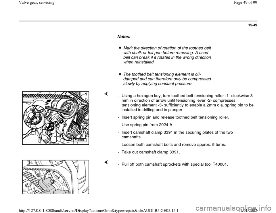
- Using a hexagon key, turn toothed belt tensioning roller -1- clockwise 8
mm in direction of arrow until tensioning lever -2- compresses
tensioning element -3- sufficiently to enable a 2mm dia. spring pin to be
installed in drilling and in plunger.
- Insert spring pin and release toothed belt tensioning roller.
Use spring pin from 2024 A.
- Insert camshaft clamp 3391 in the securing plates of the two
camshafts.
- Loosen both camshaft bolts and remove approx. 5 turns.
- Take out camshaft clamp 3391.
- Pull off both camshaft sprockets with special tool T40001.
Pa
ge 49 of 99 Valve
gear, servicin
g
11/21/2002 htt
p://127.0.0.1:8080/audi/servlet/Dis
play?action=Goto&t
yp
e=re
pair&id=AUDI.B5.GE05.15.1
Page 77 of 99
15-76
Right cylinder head
- Remove right-hand cylinder head cover Page
15
-25
All:
- Unbolt Hall sensor housing (10 Nm).
- Remove bolt securing Hall sensor rotor (20 Nm)
and carefully lever off rotor using a screwdriver.
- Insert camshaft clamp 3391 in securing plates of
two camshafts.
- Loosen both camshaft bolts and remove approx.
5 turns.
- Take out camshaft clamp 3391.
Pa
ge 77 of 99 Valve
gear, servicin
g
11/21/2002 htt
p://127.0.0.1:8080/audi/servlet/Dis
play?action=Goto&t
yp
e=re
pair&id=AUDI.B5.GE05.15.1
Page 78 of 99
15-77
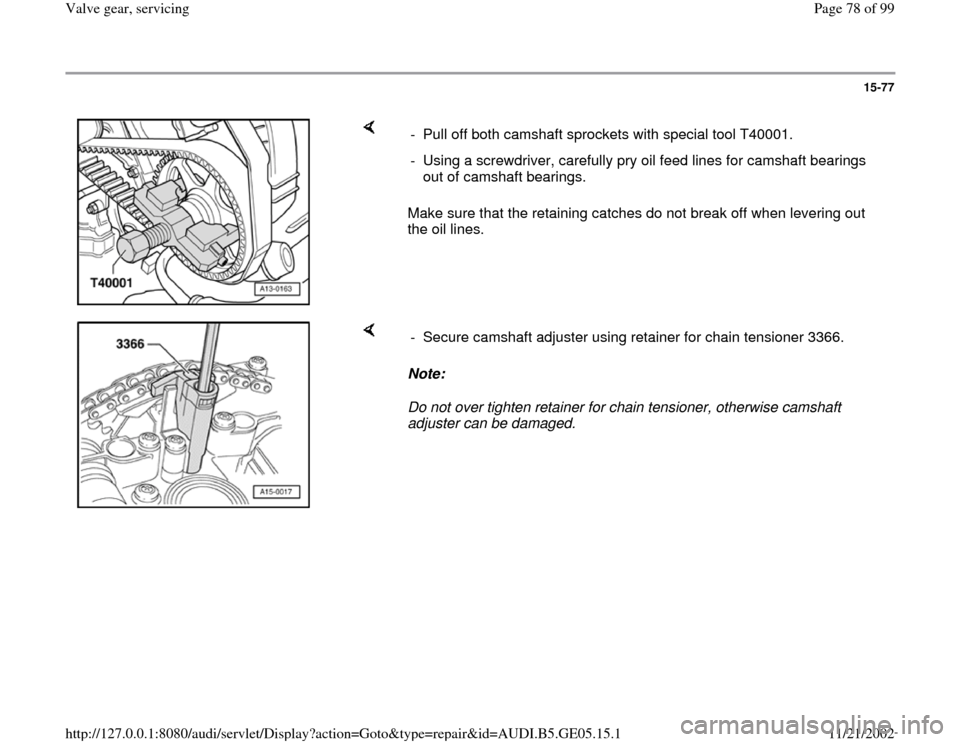
Make sure that the retaining catches do not break off when levering out
the oil lines. - Pull off both camshaft sprockets with special tool T40001.
- Using a screwdriver, carefully pry oil feed lines for camshaft bearings
out of camshaft bearings.
Note:
Do not over tighten retainer for chain tensioner, otherwise camshaft
adjuster can be damaged. - Secure camshaft adjuster using retainer for chain tensioner 3366.
Pa
ge 78 of 99 Valve
gear, servicin
g
11/21/2002 htt
p://127.0.0.1:8080/audi/servlet/Dis
play?action=Goto&t
yp
e=re
pair&id=AUDI.B5.GE05.15.1
Page 80 of 99
15-79
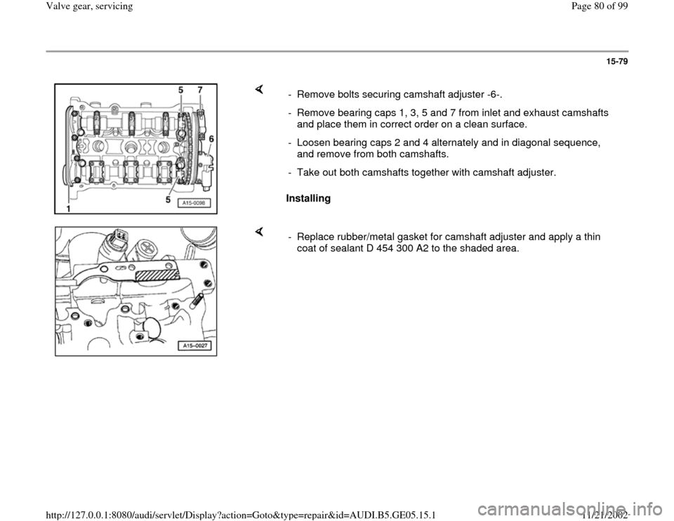
Installing - Remove bolts securing camshaft adjuster -6-.
- Remove bearing caps 1, 3, 5 and 7 from inlet and exhaust camshafts
and place them in correct order on a clean surface.
- Loosen bearing caps 2 and 4 alternately and in diagonal sequence,
and remove from both camshafts.
- Take out both camshafts together with camshaft adjuster.
- Replace rubber/metal gasket for camshaft adjuster and apply a thin
coat of sealant D 454 300 A2 to the shaded area.
Pa
ge 80 of 99 Valve
gear, servicin
g
11/21/2002 htt
p://127.0.0.1:8080/audi/servlet/Dis
play?action=Goto&t
yp
e=re
pair&id=AUDI.B5.GE05.15.1
Page 82 of 99

15-81
Notes:
The dowel sleeves for the bearing caps and
camshaft adjuster must be in the cylinder head.
Install the bearing caps so that the markings on
the bearing caps can be read from the inlet side
of the cylinder head.
- Tighten bolts securing chain tensioner (watch
position of dowel sleeves).
- Tighten bearing caps 2 and 4 of inlet and exhaust camshafts
alternately and in diagonal sequence (watch position of dowel sleeves).
- Install two bearing caps next to chain sprockets on inlet and exhaust
camshafts.
Pa
ge 82 of 99 Valve
gear, servicin
g
11/21/2002 htt
p://127.0.0.1:8080/audi/servlet/Dis
play?action=Goto&t
yp
e=re
pair&id=AUDI.B5.GE05.15.1
Page 87 of 99
15-86
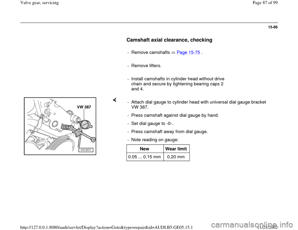
Camshaft axial clearance, checking
- Remove camshafts Page 15
-75
.
- Remove lifters.
- Install camshafts in cylinder head without drive
chain and secure by tightening bearing caps 2
and 4.
- Attach dial gauge to cylinder head with universal dial gauge bracket
VW 387.
- Press camshaft against dial gauge by hand.
- Set dial gauge to -0-.
- Press camshaft away from dial gauge.
- Note reading on gauge:
New
Wear limit
0.05 ... 0.15 mm 0.20 mm
Pa
ge 87 of 99 Valve
gear, servicin
g
11/21/2002 htt
p://127.0.0.1:8080/audi/servlet/Dis
play?action=Goto&t
yp
e=re
pair&id=AUDI.B5.GE05.15.1
Page 89 of 99
15-88
Hydraulic lifters, checking
Notes:
Replace malfunctioning lifters completely (lifters
cannot be adjusted or repaired).
When new lifters have been installed the engine
must not be started for about 30 minutes
(otherwise valves will strike pistons).
Irregular valve noises when starting engine are
normal.
- Start engine and run until coolant temperature
reaches approx. 80 C.
- Increase engine speed to about 2500 RPM for
approx. 2 minutes: if necessary, perform road
test.
If the hydraulic lifters are still noisy, locate
malfunctioning lifters as follows:
- Remove cylinder head cover.
- Rotate crankshaft clockwise by turning securing
bolt for toothed belt sprocket until cams of lifters
to be checked are pointing upward.
Pa
ge 89 of 99 Valve
gear, servicin
g
11/21/2002 htt
p://127.0.0.1:8080/audi/servlet/Dis
play?action=Goto&t
yp
e=re
pair&id=AUDI.B5.GE05.15.1
Page 92 of 99
15-91
Exhaust side
Note:
Before attaching the valve assembly appliance,
remove the two studs in the center of the cylinder
head and the three upper studs (inlet side) for
securing the cylinder head cover.
- Screw pressure hose VW 653/3 with sealing ring
finger-tight into spark plug thread of relevant
cylinder, and maintain a constant pressure of at
least 6 bar.
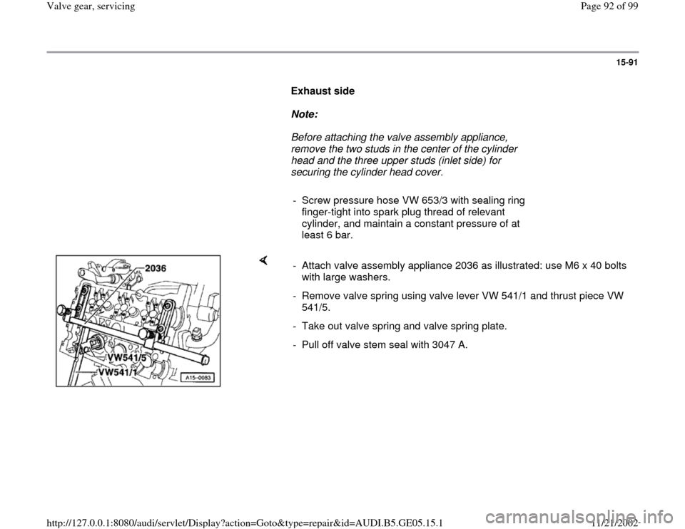
- Attach valve assembly appliance 2036 as illustrated: use M6 x 40 bolts
with large washers.
- Remove valve spring using valve lever VW 541/1 and thrust piece VW
541/5.
- Take out valve spring and valve spring plate.
- Pull off valve stem seal with 3047 A.
Pa
ge 92 of 99 Valve
gear, servicin
g
11/21/2002 htt
p://127.0.0.1:8080/audi/servlet/Dis
play?action=Goto&t
yp
e=re
pair&id=AUDI.B5.GE05.15.1
Page 93 of 99
15-92
Inlet side
Note:
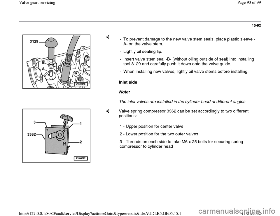
The inlet valves are installed in the cylinder head at different angles. - To prevent damage to the new valve stem seals, place plastic sleeve -
A- on the valve stem.
- Lightly oil sealing lip.
- Insert valve stem seal -B- (without oiling outside of seal) into installing
tool 3129 and carefully push it down onto the valve guide.
- When installing new valves, lightly oil valve stems before installing.
Valve spring compressor 3362 can be set accordingly to two different
positions:
1 - Upper position for center valve
2 - Lower position for the two outer valves
3 - Threads on each side to take M6 x 25 bolts for securing spring
compressor to cylinder head
Pa
ge 93 of 99 Valve
gear, servicin
g
11/21/2002 htt
p://127.0.0.1:8080/audi/servlet/Dis
play?action=Goto&t
yp
e=re
pair&id=AUDI.B5.GE05.15.1