power AUDI A4 1999 B5 / 1.G ATW Engine Ignition System Workshop Manual
[x] Cancel search | Manufacturer: AUDI, Model Year: 1999, Model line: A4, Model: AUDI A4 1999 B5 / 1.GPages: 59, PDF Size: 0.53 MB
Page 3 of 59
28-3
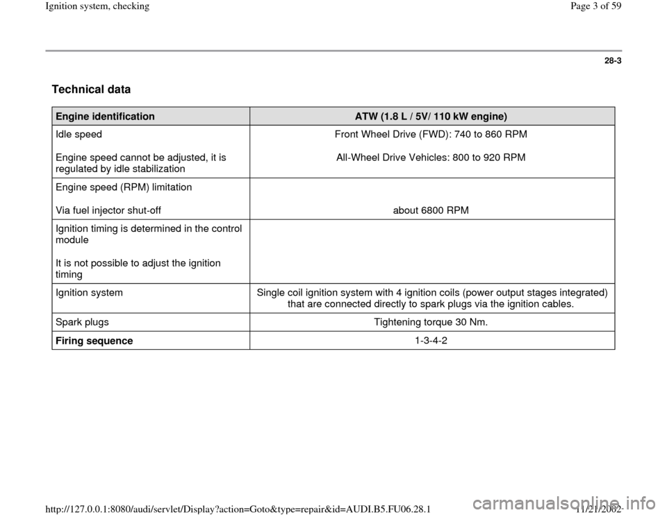
Technical data
Engine identification
ATW (1.8 L / 5V/ 110 kW engine)
Idle speed
Engine speed cannot be adjusted, it is
regulated by idle stabilization Front Wheel Drive (FWD): 740 to 860 RPM
All-Wheel Drive Vehicles: 800 to 920 RPM
Engine speed (RPM) limitation
Via fuel injector shut-off
about 6800 RPM
Ignition timing is determined in the control
module
It is not possible to adjust the ignition
timing
Ignition system Single coil ignition system with 4 ignition coils (power output stages integrated)
that are connected directly to spark plugs via the ignition cables.
Spark plugs Tightening torque 30 Nm.
Firing sequence 1-3-4-2
Pa
ge 3 of 59 I
gnition s
ystem, checkin
g
11/21/2002 htt
p://127.0.0.1:8080/audi/servlet/Dis
play?action=Goto&t
yp
e=re
pair&id=AUDI.B5.FU06.28.1
Page 4 of 59
28-4
Ignition coils with power output stages,
checking
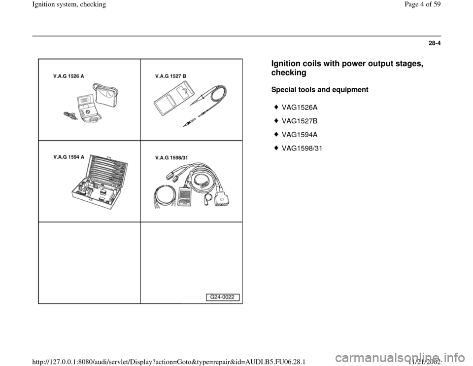
Special tools and equipment
VAG1526A
VAG1527B
VAG1594A
VAG1598/31
Pa
ge 4 of 59 I
gnition s
ystem, checkin
g
11/21/2002 htt
p://127.0.0.1:8080/audi/servlet/Dis
play?action=Goto&t
yp
e=re
pair&id=AUDI.B5.FU06.28.1
Page 5 of 59
28-5
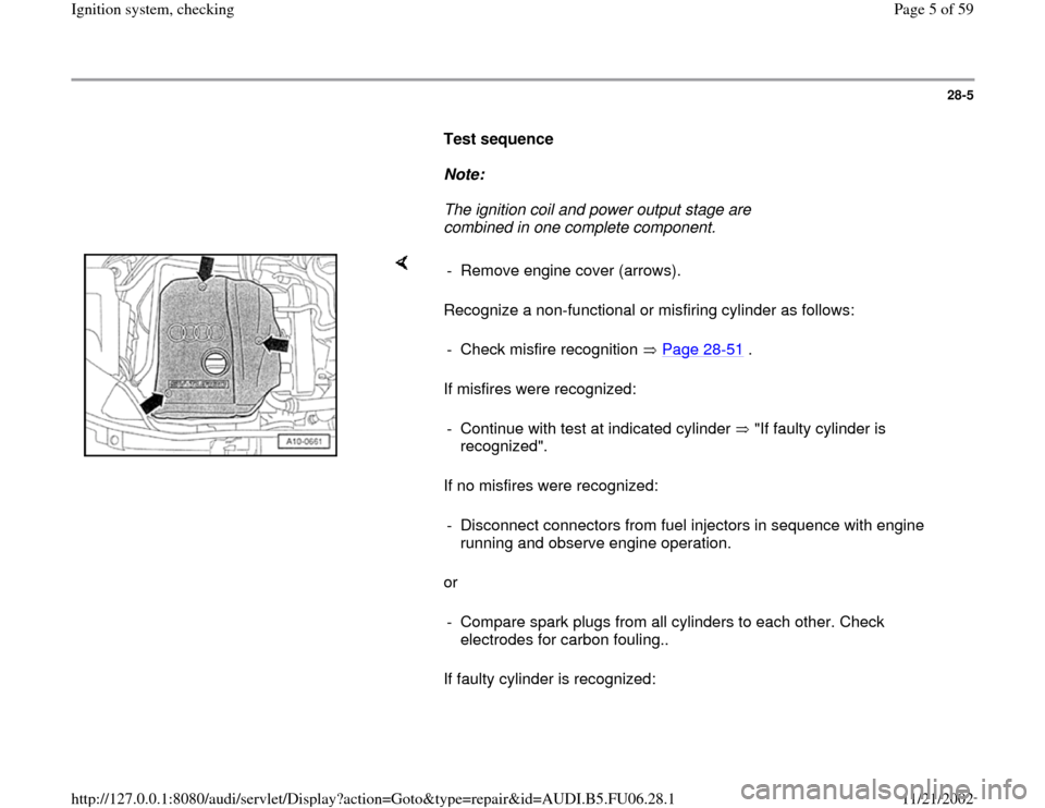
Test sequence
Note:
The ignition coil and power output stage are
combined in one complete component.
Recognize a non-functional or misfiring cylinder as follows:
If misfires were recognized:
If no misfires were recognized:
or
If faulty cylinder is recognized: - Remove engine cover (arrows).
- Check misfire recognition Page 28
-51
.
- Continue with test at indicated cylinder "If faulty cylinder is
recognized". - Disconnect connectors from fuel injectors in sequence with engine
running and observe engine operation.
- Compare spark plugs from all cylinders to each other. Check
electrodes for carbon fouling..
Pa
ge 5 of 59 I
gnition s
ystem, checkin
g
11/21/2002 htt
p://127.0.0.1:8080/audi/servlet/Dis
play?action=Goto&t
yp
e=re
pair&id=AUDI.B5.FU06.28.1
Page 9 of 59
28-8
If specified value is obtained:
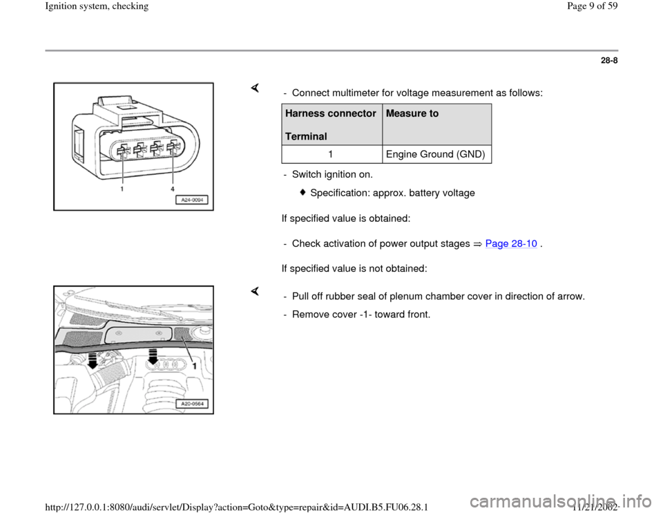
If specified value is not obtained: - Connect multimeter for voltage measurement as follows:Harness connector
Terminal
Measure to
1 Engine Ground (GND)
- Switch ignition on.
Specification: approx. battery voltage
- Check activation of power output stages Page 28
-10
.
- Pull off rubber seal of plenum chamber cover in direction of arrow.
- Remove cover -1- toward front.
Pa
ge 9 of 59 I
gnition s
ystem, checkin
g
11/21/2002 htt
p://127.0.0.1:8080/audi/servlet/Dis
play?action=Goto&t
yp
e=re
pair&id=AUDI.B5.FU06.28.1
Page 11 of 59
28-10
- Perform following tests marked with dots:
Checking activation of power output stages
Note:
Fuel must not be injected during the test to avoid damaging catalytic
converter. Connectors must therefore be disconnected from fuel injectors.
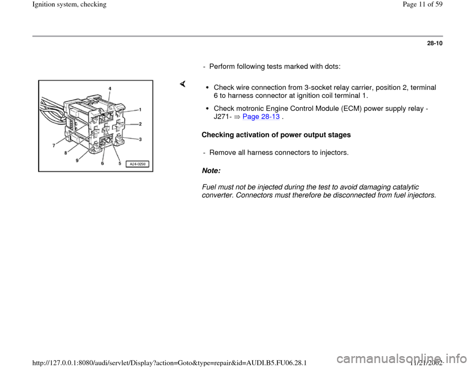
Check wire connection from 3-socket relay carrier, position 2, terminal
6 to harness connector at ignition coil terminal 1. Check motronic Engine Control Module (ECM) power supply relay -
J271- Page 28
-13
.
- Remove all harness connectors to injectors.
Pa
ge 11 of 59 I
gnition s
ystem, checkin
g
11/21/2002 htt
p://127.0.0.1:8080/audi/servlet/Dis
play?action=Goto&t
yp
e=re
pair&id=AUDI.B5.FU06.28.1
Page 13 of 59
28-12
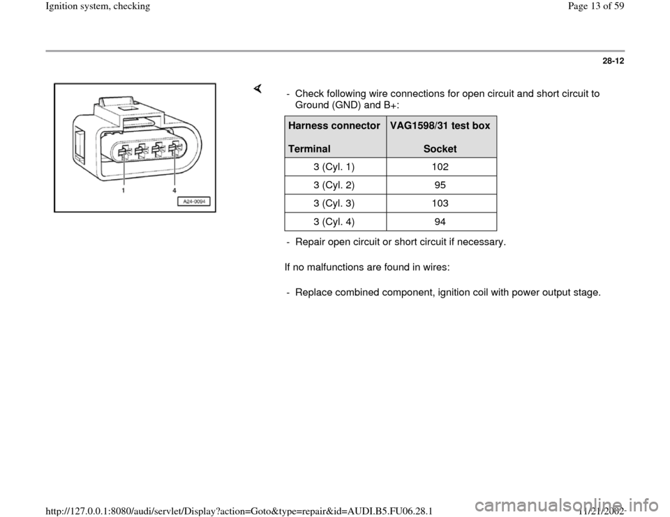
If no malfunctions are found in wires: - Check following wire connections for open circuit and short circuit to
Ground (GND) and B+: Harness connector
Terminal
VAG1598/31 test box
Socket
3 (Cyl. 1) 102
3 (Cyl. 2) 95
3 (Cyl. 3) 103
3 (Cyl. 4) 94
- Repair open circuit or short circuit if necessary.
- Replace combined component, ignition coil with power output stage.
Pa
ge 13 of 59 I
gnition s
ystem, checkin
g
11/21/2002 htt
p://127.0.0.1:8080/audi/servlet/Dis
play?action=Goto&t
yp
e=re
pair&id=AUDI.B5.FU06.28.1
Page 14 of 59
28-13
Motronic Engine Control Module (ECM)
power supply relay -J271-, checking
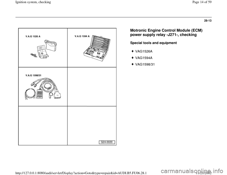
Special tools and equipment
VAG1526A
VAG1594A
VAG1598/31
Pa
ge 14 of 59 I
gnition s
ystem, checkin
g
11/21/2002 htt
p://127.0.0.1:8080/audi/servlet/Dis
play?action=Goto&t
yp
e=re
pair&id=AUDI.B5.FU06.28.1
Page 15 of 59
28-14
Note:
The motronic Engine Control Module (ECM)
power supply relay -J271- supplies voltage to the
ignition coils with power output stages and the
Engine Control Module (ECM) at pin 121.
Test requirement:
Fuses for engine electronics OK
Electrical Wiring Diagrams, Troubleshooting &
Component Locations
Test sequence
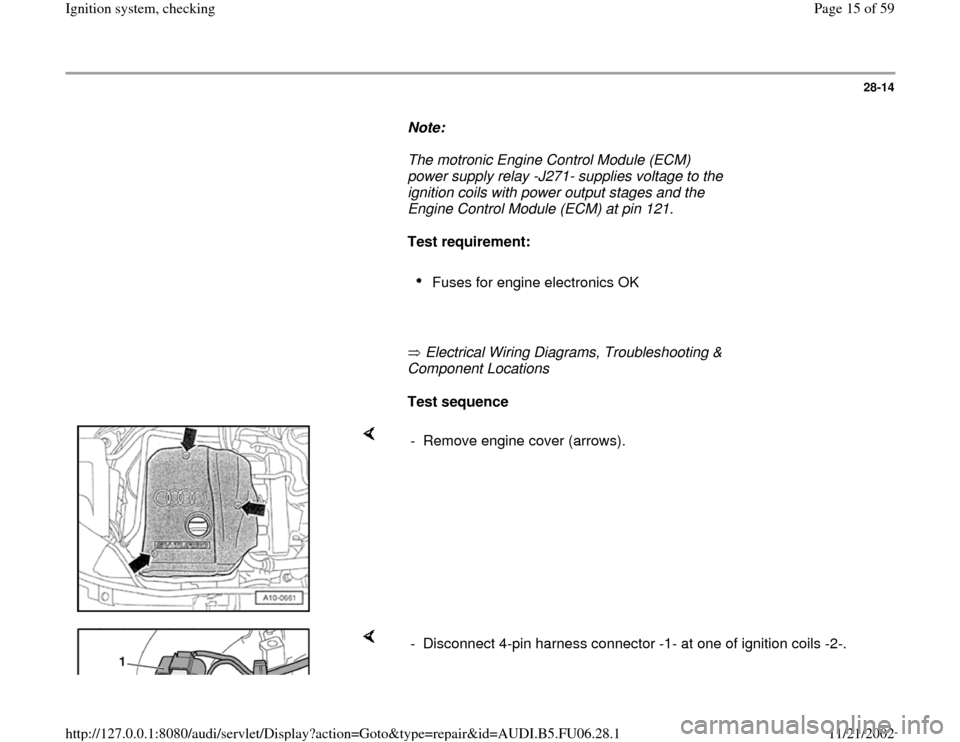
- Remove engine cover (arrows).
- Disconnect 4-pin harness connector -1- at one of ignition coils -2-.
Pa
ge 15 of 59 I
gnition s
ystem, checkin
g
11/21/2002 htt
p://127.0.0.1:8080/audi/servlet/Dis
play?action=Goto&t
yp
e=re
pair&id=AUDI.B5.FU06.28.1
Page 18 of 59
28-17
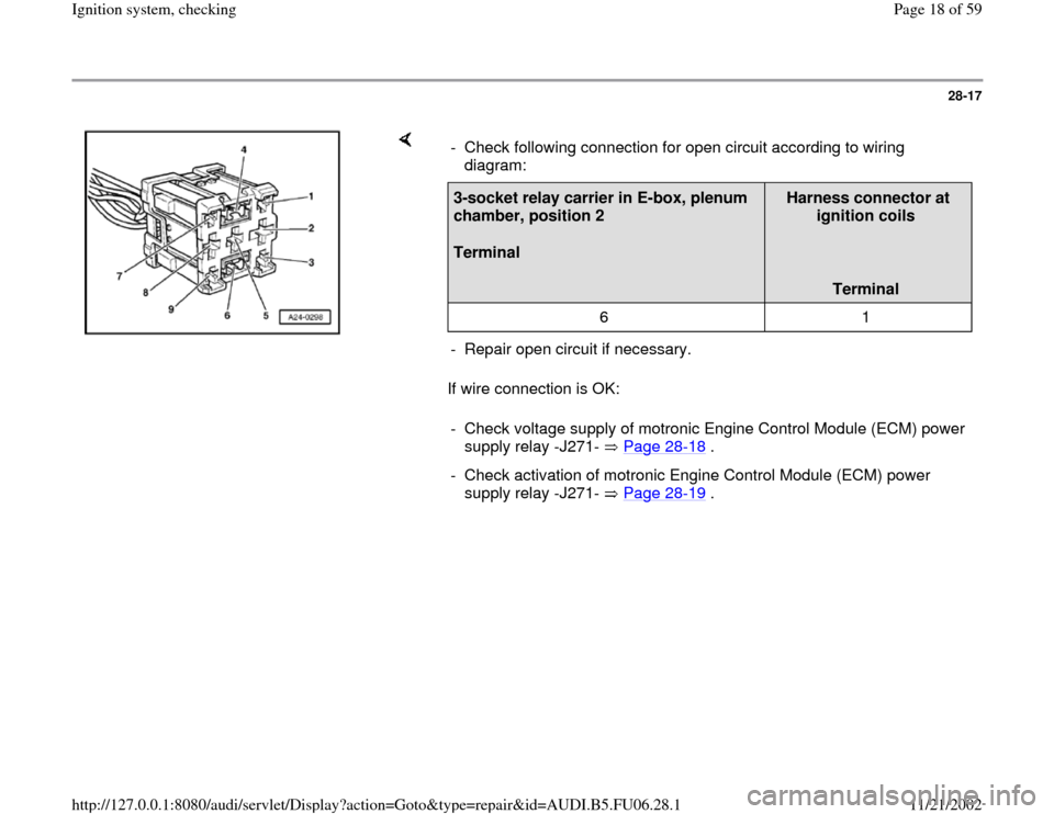
If wire connection is OK: - Check following connection for open circuit according to wiring
diagram: 3-socket relay carrier in E-box, plenum
chamber, position 2
Terminal
Harness connector at
ignition coils
Terminal
6 1
- Repair open circuit if necessary.
- Check voltage supply of motronic Engine Control Module (ECM) power
supply relay -J271- Page 28
-18
.
- Check activation of motronic Engine Control Module (ECM) power
supply relay -J271- Page 28
-19
.
Pa
ge 18 of 59 I
gnition s
ystem, checkin
g
11/21/2002 htt
p://127.0.0.1:8080/audi/servlet/Dis
play?action=Goto&t
yp
e=re
pair&id=AUDI.B5.FU06.28.1
Page 21 of 59
28-20
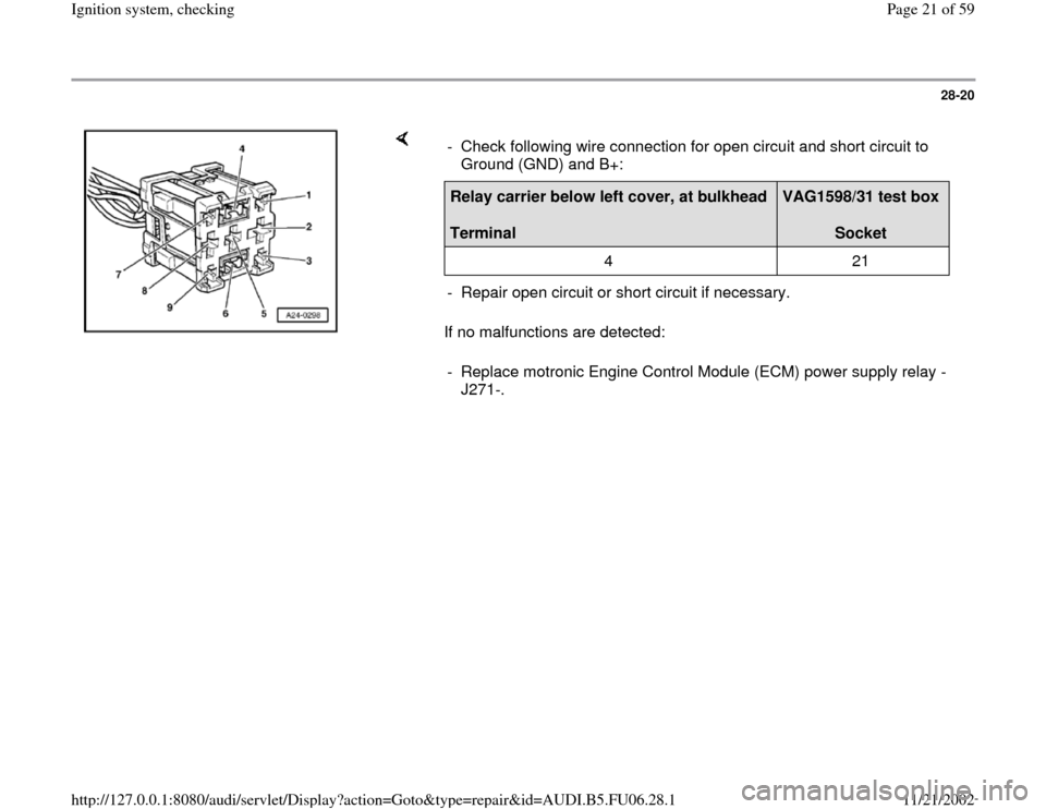
If no malfunctions are detected: - Check following wire connection for open circuit and short circuit to
Ground (GND) and B+: Relay carrier below left cover, at bulkhead
Terminal
VAG1598/31 test box
Socket
4 21
- Repair open circuit or short circuit if necessary.
- Replace motronic Engine Control Module (ECM) power supply relay -
J271-.
Pa
ge 21 of 59 I
gnition s
ystem, checkin
g
11/21/2002 htt
p://127.0.0.1:8080/audi/servlet/Dis
play?action=Goto&t
yp
e=re
pair&id=AUDI.B5.FU06.28.1