AUDI A4 2000 B5 / 1.G AWM Engine Motronic Injection System Servicing Repair Manual
Manufacturer: AUDI, Model Year: 2000,
Model line: A4,
Model: AUDI A4 2000 B5 / 1.G
Pages: 79, PDF Size: 1.04 MB
AUDI A4 2000 B5 / 1.G AWM Engine Motronic Injection System Servicing Repair Manual
A4 2000 B5 / 1.G
AUDI
AUDI
https://www.carmanualsonline.info/img/6/1091/w960_1091-0.png
AUDI A4 2000 B5 / 1.G AWM Engine Motronic Injection System Servicing Repair Manual
Trending: automatic transmission, engine oil, ECU, air condition, fuse box location, fuel, wheel
Page 61 of 79
24-55
If specified value is not obtained:
- Replace central electronics.
Checking activation of Fuel Pump (FP) relay
- Switch ignition off.
- Connect VAG1598/31 test box at wiring harness
to Engine Control Module (ECM), do not connect
ECM Page 24
-19
.
- Switch ignition on.
- Bridge terminals 1 and 65 at test box using wires
from VAG1594A adapter test kit.
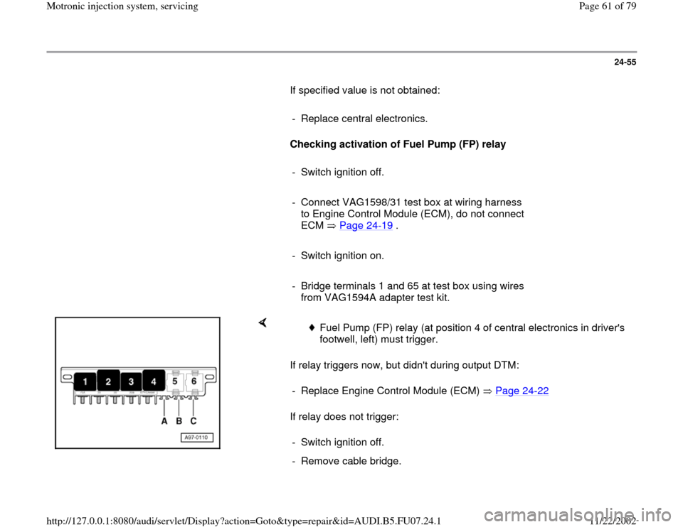
If relay triggers now, but didn't during output DTM:
If relay does not trigger:
Fuel Pump (FP) relay (at position 4 of central electronics in driver's
footwell, left) must trigger.
- Replace Engine Control Module (ECM) Page 24
-22
- Switch ignition off.
- Remove cable bridge.
Pa
ge 61 of 79 Motronic in
jection s
ystem, servicin
g
11/22/2002 htt
p://127.0.0.1:8080/audi/servlet/Dis
play?action=Goto&t
yp
e=re
pair&id=AUDI.B5.FU07.24.1
Page 62 of 79
- Remove Fuel Pump (FP) relay.
Pa
ge 62 of 79 Motronic in
jection s
ystem, servicin
g
11/22/2002 htt
p://127.0.0.1:8080/audi/servlet/Dis
play?action=Goto&t
yp
e=re
pair&id=AUDI.B5.FU07.24.1
Page 63 of 79
24-56
If specified value is not obtained:
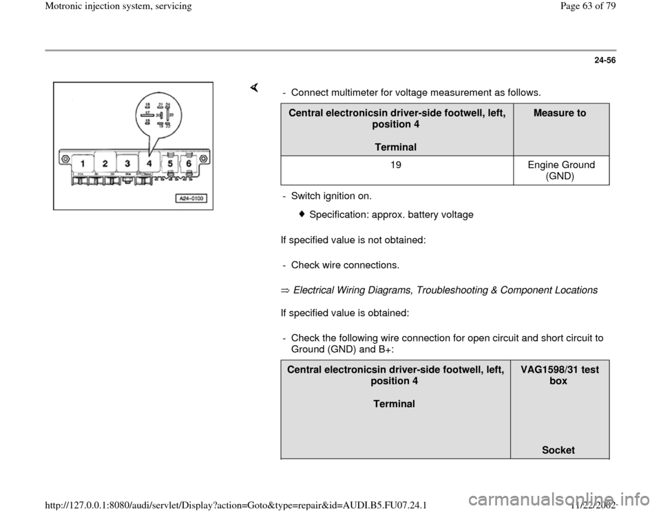
Electrical Wiring Diagrams, Troubleshooting & Component Locations
If specified value is obtained: - Connect multimeter for voltage measurement as follows.Central electronicsin driver-side footwell, left,
position 4
Terminal
Measure to
19 Engine Ground
(GND)
- Switch ignition on.
Specification: approx. battery voltage
- Check wire connections.
- Check the following wire connection for open circuit and short circuit to
Ground (GND) and B+: Central electronicsin driver-side footwell, left,
position 4
Terminal
VAG1598/31 test
box
Socket
Pa
ge 63 of 79 Motronic in
jection s
ystem, servicin
g
11/22/2002 htt
p://127.0.0.1:8080/audi/servlet/Dis
play?action=Goto&t
yp
e=re
pair&id=AUDI.B5.FU07.24.1
Page 64 of 79
16 65
Pa
ge 64 of 79 Motronic in
jection s
ystem, servicin
g
11/22/2002 htt
p://127.0.0.1:8080/audi/servlet/Dis
play?action=Goto&t
yp
e=re
pair&id=AUDI.B5.FU07.24.1
Page 65 of 79
24-57
- Repair open circuit or short circuit if
necessary.
If no malfunctions are detected:
- Replace Fuel Pump (FP) relay -J17-.
- Re-connect Engine Control Module (ECM).
Check voltage supply for Fuel Pump (FP) and
components
- Remove fuses S228, S232, and S234 (positions 28, 32, and 34) from
fuse holder.
- Initiate output Diagnostic Test Mode (DTM) Page 01
-51
and activate
Evaporative Emission (EVAP) canister purge regulator valve -N80-.
- Connect multimeter for voltage measurement to Ground (GND) and to
one terminal of the following fuses in the fuse holder. Circlip
Specified value at one of the terminals
S228 approx. battery voltage
S232 approx. battery voltage
S234 approx. battery voltage
Pa
ge 65 of 79 Motronic in
jection s
ystem, servicin
g
11/22/2002 htt
p://127.0.0.1:8080/audi/servlet/Dis
play?action=Goto&t
yp
e=re
pair&id=AUDI.B5.FU07.24.1
Page 66 of 79
24-58
If specified values are not obtained:
- Repeat test at another terminal of fuse socket.
If specified values are not obtained again:
- Check wire connections.
Electrical Wiring Diagrams, Troubleshooting &
Component Locations If no malfunctions are detected:
- Replace Fuel Pump (FP) relay -J17-.
- Re-insert the fuses.
Pa
ge 66 of 79 Motronic in
jection s
ystem, servicin
g
11/22/2002 htt
p://127.0.0.1:8080/audi/servlet/Dis
play?action=Goto&t
yp
e=re
pair&id=AUDI.B5.FU07.24.1
Page 67 of 79
24-59
Mass Air Flow (MAF) sensor -G70-,
checking
Special Tools and Equipment
VAG1526A
VAG1594A
VAG1598/31
VAS5051 with VAG5051/1
Pa
ge 67 of 79 Motronic in
jection s
ystem, servicin
g
11/22/2002 htt
p://127.0.0.1:8080/audi/servlet/Dis
play?action=Goto&t
yp
e=re
pair&id=AUDI.B5.FU07.24.1
Page 68 of 79
24-60
Component location Overview of component
locations Page 24
-5
Test requirements:
Coolant Temperature at least 80 C.
Electrical consumers switched off (radiator
fan must NOT run during test).
A/C switched off.
Checking function
- Connect VAS5051 tester Page 01
-7 and
select vehicle system "01 - Engine electronics".
Engine must run at idle for this.
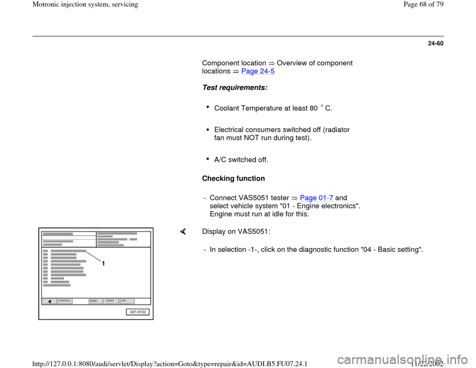
Display on VAS5051:
- In selection -1-, click on the diagnostic function "04 - Basic setting".
Pa
ge 68 of 79 Motronic in
jection s
ystem, servicin
g
11/22/2002 htt
p://127.0.0.1:8080/audi/servlet/Dis
play?action=Goto&t
yp
e=re
pair&id=AUDI.B5.FU07.24.1
Page 69 of 79
24-61
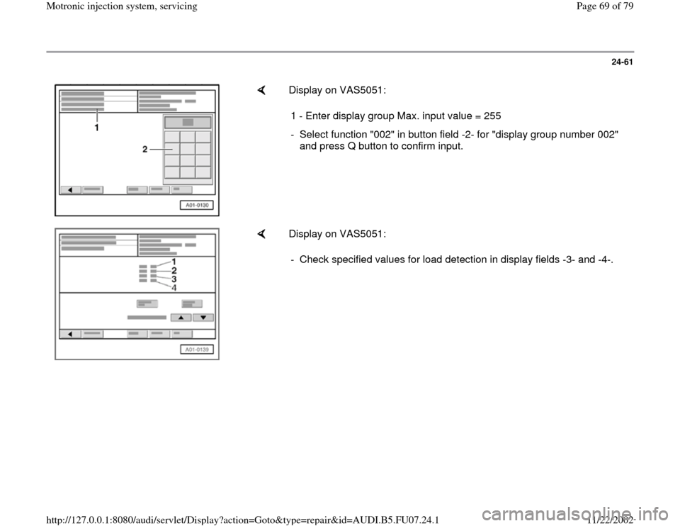
Display on VAS5051:
1 - Enter display group Max. input value = 255
- Select function "002" in button field -2- for "display group number 002"
and press Q button to confirm input.
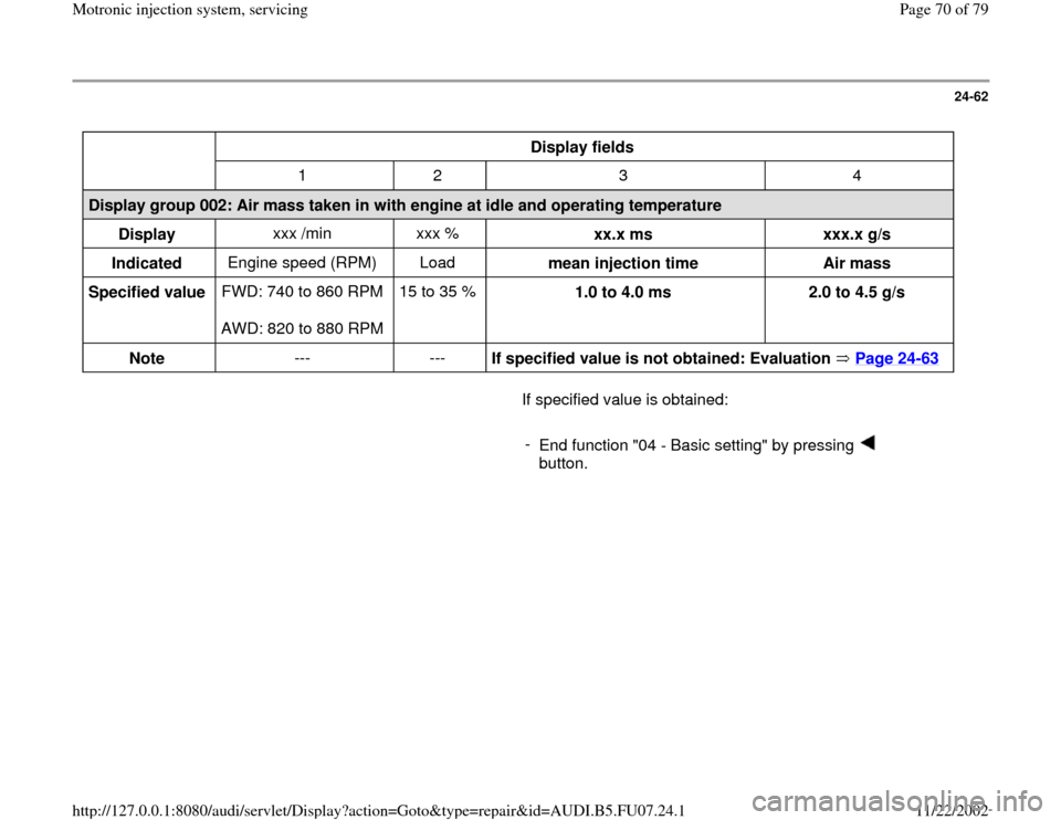
Display on VAS5051:
- Check specified values for load detection in display fields -3- and -4-.
Pa
ge 69 of 79 Motronic in
jection s
ystem, servicin
g
11/22/2002 htt
p://127.0.0.1:8080/audi/servlet/Dis
play?action=Goto&t
yp
e=re
pair&id=AUDI.B5.FU07.24.1
Page 70 of 79
24-62
Display fields
1 2 3 4
Display group 002: Air mass taken in with engine at idle and operating temperature
Display xxx /min xxx %
xx.x ms
xxx.x g/s
Indicated Engine speed (RPM) Load
mean injection time
Air mass
Specified value FWD: 740 to 860 RPM
AWD: 820 to 880 RPM 15 to 35 %
1.0 to 4.0 ms
2.0 to 4.5 g/s
Note --- ---
If specified value is not obtained: Evaluation Page 24
-63
If specified value is obtained:
-
End function "04 - Basic setting" by pressing
button.
Pa
ge 70 of 79 Motronic in
jection s
ystem, servicin
g
11/22/2002 htt
p://127.0.0.1:8080/audi/servlet/Dis
play?action=Goto&t
yp
e=re
pair&id=AUDI.B5.FU07.24.1
Trending: sensor, wiring diagram, air condition, check engine light, fuel, brake sensor, fuse box
