ignition AUDI A4 2000 B5 / 1.G Brakes ESP DTC Table Workshop Manual
[x] Cancel search | Manufacturer: AUDI, Model Year: 2000, Model line: A4, Model: AUDI A4 2000 B5 / 1.GPages: 96, PDF Size: 0.3 MB
Page 1 of 96

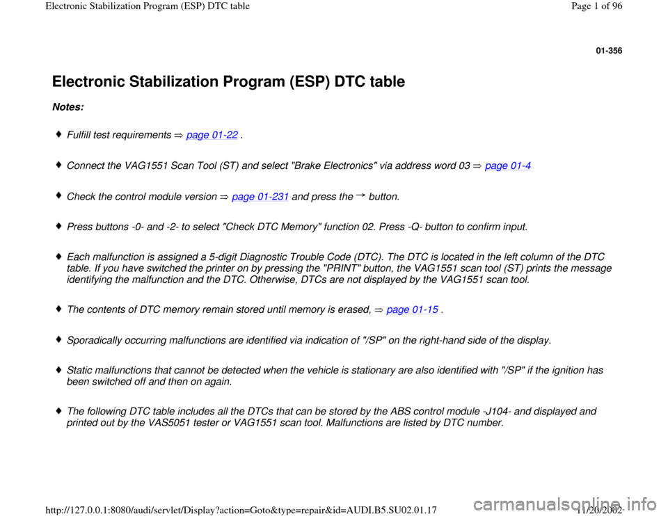
01-356
Electronic Stabilization Program (ESP) DTC table Notes:
Fulfill test requirements page 01
-22
.
Connect the VAG1551 Scan Tool (ST) and select "Brake Electronics" via address word 03 page 01
-4
Check the control module version page 01
-231
and press the button.
Press buttons -0- and -2- to select "Check DTC Memory" function 02. Press -Q- button to confirm input.
Each malfunction is assigned a 5-digit Diagnostic Trouble Code (DTC). The DTC is located in the left column of the DTC
table. If you have switched the printer on by pressing the "PRINT" button, the VAG1551 scan tool (ST) prints the message
identifying the malfunction and the DTC. Otherwise, DTCs are not displayed by the VAG1551 scan tool.
The contents of DTC memory remain stored until memory is erased, page 01
-15
.
Sporadically occurring malfunctions are identified via indication of "/SP" on the right-hand side of the display.
Static malfunctions that cannot be detected when the vehicle is stationary are also identified with "/SP" if the ignition has
been switched off and then on again.
The following DTC table includes all the DTCs that can be stored by the ABS control module -J104- and displayed and
printed out by the VAS5051 tester or VAG1551 scan tool. Malfunctions are listed by DTC number.
Pa
ge 1 of 96 Electronic Stabilization Pro
gram
(ESP
) DTC table
11/20/2002 htt
p://127.0.0.1:8080/audi/servlet/Dis
play?action=Goto&t
yp
e=re
pair&id=AUDI.B5.SU02.01.17
Page 77 of 96

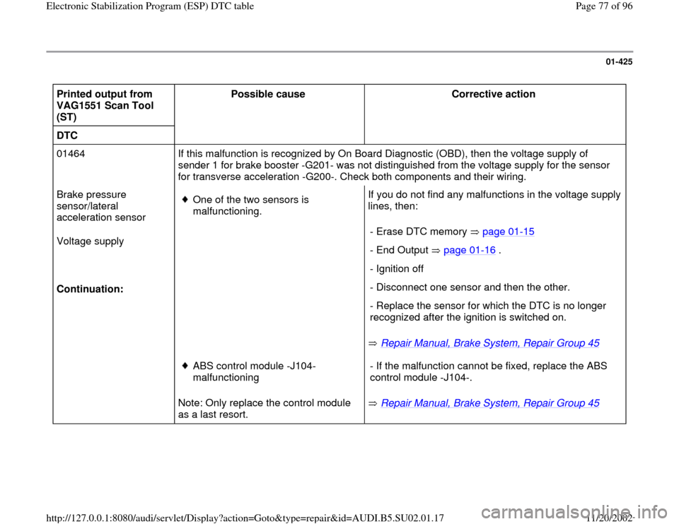
01-425
Printed output from
VAG1551 Scan Tool
(ST) Possible cause
Corrective action
DTC
01464 If this malfunction is recognized by On Board Diagnostic (OBD), then the voltage supply of
sender 1 for brake booster -G201- was not distinguished from the voltage supply for the sensor
for transverse acceleration -G200-. Check both components and their wiring.
Brake pressure
sensor/lateral
acceleration sensor
Voltage supply
Continuation:
One of the two sensors is
malfunctioning. If you do not find any malfunctions in the voltage supply
lines, then:
Repair Manual, Brake System, Repair Group 45
- Erase DTC memory page 01
-15
- End Output page 01
-16
.
- Ignition off
- Disconnect one sensor and then the other.
- Replace the sensor for which the DTC is no longer
recognized after the ignition is switched on.
Note: Only replace the control module
as a last resort.
ABS control module -J104-
malfunctioning
Repair Manual, Brake System, Repair Group 45
- If the malfunction cannot be fixed, replace the ABS
control module -J104-.
Pa
ge 77 of 96 Electronic Stabilization Pro
gram
(ESP
) DTC table
11/20/2002 htt
p://127.0.0.1:8080/audi/servlet/Dis
play?action=Goto&t
yp
e=re
pair&id=AUDI.B5.SU02.01.17