brake AUDI A4 2000 B5 / 1.G Instrument Cluster Location Diagram Through Model Year 2000 Workshop Manual
Page 8 of 28

Page 9 of 28

Page 10 of 28

Page 12 of 28

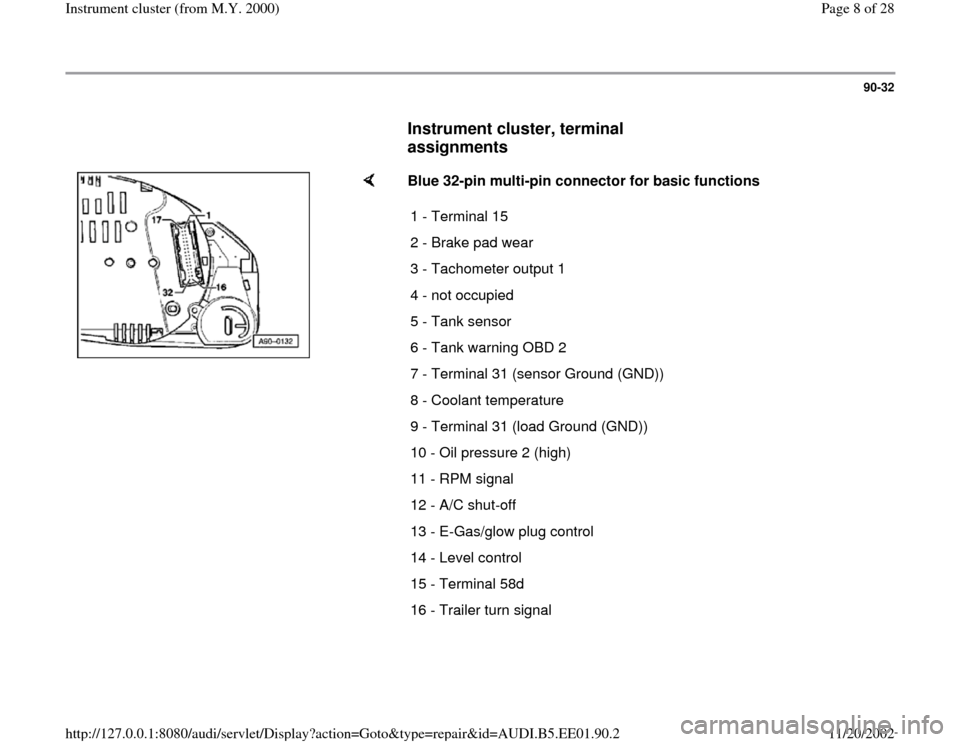
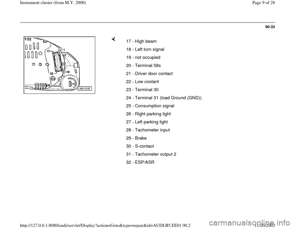
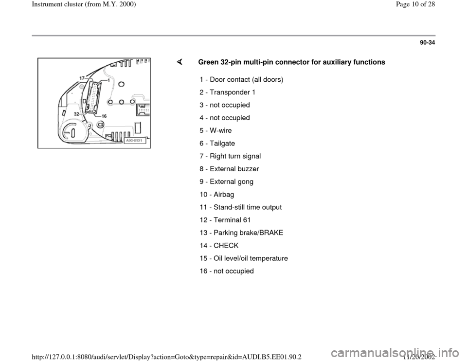
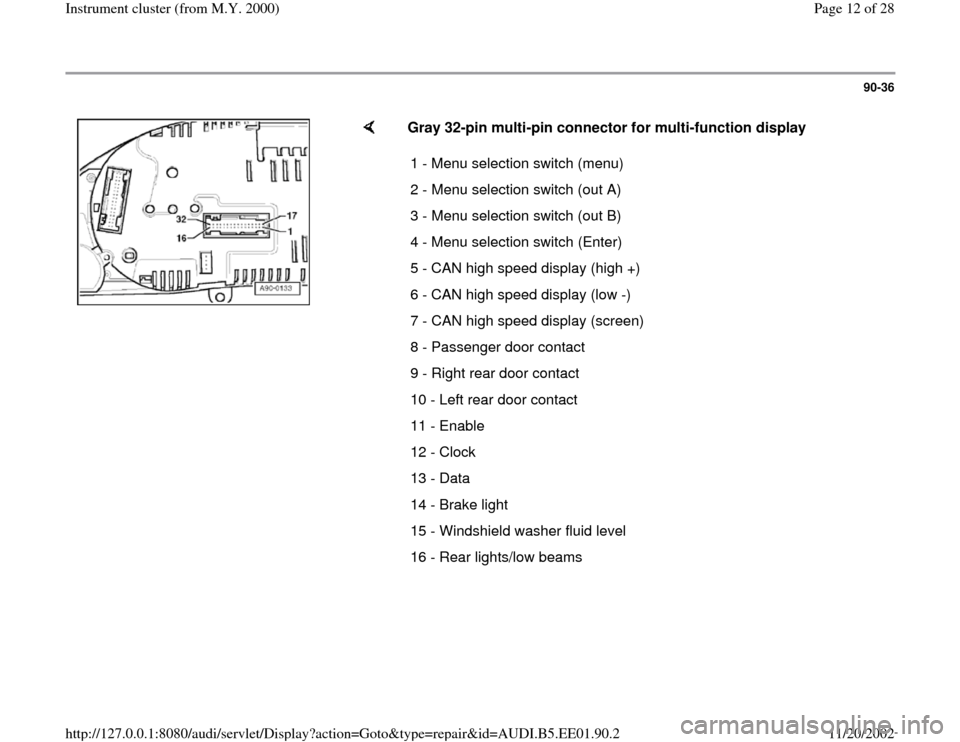
View, print and download for free: brake - AUDI A4 2000 B5 / 1.G Instrument Cluster Location Diagram Through Model Year 2000 Workshop Manual, 28 Pages, PDF Size: 0.15 MB. Search in AUDI A4 2000 B5 / 1.G Instrument Cluster Location Diagram Through Model Year 2000 Workshop Manual online. CarManualsOnline.info is the largest online database of car user manuals. AUDI A4 2000 B5 / 1.G Instrument Cluster Location Diagram Through Model Year 2000 Workshop Manual PDF Download. 90-32 Instrument cluster, terminal assignments Blue 32-pin multi-pin connector for basic functions 1 - Terminal 15 2 - Brake pad wear 3 - Tacho
All product names, logos, and brands are property of their respective owners.