AUDI A4 2017 Owners Manual
Manufacturer: AUDI, Model Year: 2017, Model line: A4, Model: AUDI A4 2017Pages: 386, PDF Size: 96.32 MB
Page 351 of 386
<( a, .... N ,....
N .... 0 0
3 a,
~ If the removed wheel does not fit in the spare
whee l we ll, store it securely in the luggage
compartment ¢
page 242.
~ Check the tire pressure on the installed whee l
as soon as possible.
~ On vehicles with a Tire Pressure Monitoring Sys
tem*, check the tire pressure and store it in the
Infotainment system
<::;> page 336 .
~ The wheel bolt tightening specification must be
90
ft lbs (120 Nm). Check it as soon as possible
with a torque wrench . Drive carefully until then.
~ Have the faulty wheel replaced as quickly as
possible.
(D Tips
- If you notice that the wheel bolts are cor
roded and difficult to turn while changing a
tire, they should be replaced before you
check the tightening torque.
- Drive at reduced speed until you have the
tightening torques checked.
Notes on wheel changing
Please read the information ¢ page 324 if you
are go ing to use a replacement tire which is dif
ferent from the tires on your vehicle.
After you change a tire:
- Check the tire pressure on the replacement
tire immediately after installation.
- Have the wheel bolt tightening torque
checked with a torque wrench as soon as pos
sible by your authorized Audi dealer or quali
fied workshop.
- With steel and alloy wheel rims, the wheel
bolts are correctly tightened at a torque of
90 ft lbs (120 Nm).
- If you notice that the wheel bolts are corroded
and difficult to turn while changing a tire,
they should be replaced before you check the
tightening torque.
- Replace the flat tire with a new one and have
it installed on your vehicle as soon as possi
ble . Remount the wheel cover.
Until then, drive with extra care and at reduced
speeds .
Emergency assistance
A WARNING
- If you are going to equip your vehicle with
tires or rims which differ from those which
were factory installed, then be sure to read
the information
r::;> page 324.
-Always make sure the damaged wheel or
even a flat tire and the jack and tool kit are
p ro perly secured in the luggage compart
ment and are not loose in the passenger
compa rtment.
- In an accident or sudde n maneuver they
could fly forward , injur ing anyone in the ve
h icl e.
- Always store damaged wheel, jack and tools
securely in the luggage compartment. Oth
erwise, in an acc ident or sudden maneuver
they could fly forward, causing injury to pas
sengers in the ve hicle.
Space-saving spare tire
Applies to: vehicles with space-saving spare tire
-
The spare tire is intended fo r short-term use on
ly. Have the damaged tire checked and replaced,
if necessary, by an authorized Audi dea ler or au
thori zed Audi Service Facility as soon as possible.
T he re are some restrictions on the use of the
spare tire. The spare tire has been designed spe
cifically for your type of vehicle . Do not rep lace it
with the spare tire from another type of vehicle .
T he tire press ure must be 61 PS I (420 kPA).
Removing the spare tire
~ Lift the cargo floor using the p lastic handle and
hook the handl e onto the luggage compa rt
ment seal
¢page 343, fig . 258.
~ Remove the handle by turning it counter-clock
wise and remove the spare tire.
~ Unhook the cargo floor before closing the rear
lid.
Snow chains
For technical reasons, the use of snow chains on
the compact spare tire is not pe rmitted .
If you have to drive w ith snow chains and a front
tire fails , mount the spare wheel in place of a .,..
349
Page 352 of 386
Emergency assistance
rear tire . Insta ll the snow cha ins on the rear tire
that you removed, and install that in p lace of the
f ront tire that failed.
A WARNING
- After installing a spare t ire, the tire p res
s u re must be chec ked as quickly as poss ible.
- Do not drive faster than 50 mph (80 km/h) with a compact spare tire. Driving faster
th an that increases the risk of an accident.
- T o reduce the risk of an accident, avo id f ull
throttle acceleration, heavy braking, and
fast cornering with the compact spa re t ire.
- Never dr ive using more than one spare
wheel and tire . You risk having an acc ident.
- Norma l summer or winter tires must not be
mounted on the compact spare wheel rim.
350
-
Page 353 of 386
Fuses and bulbs
Fuses
Replacing fuses
A fuse that has blown will have metal strips that
have burned through.
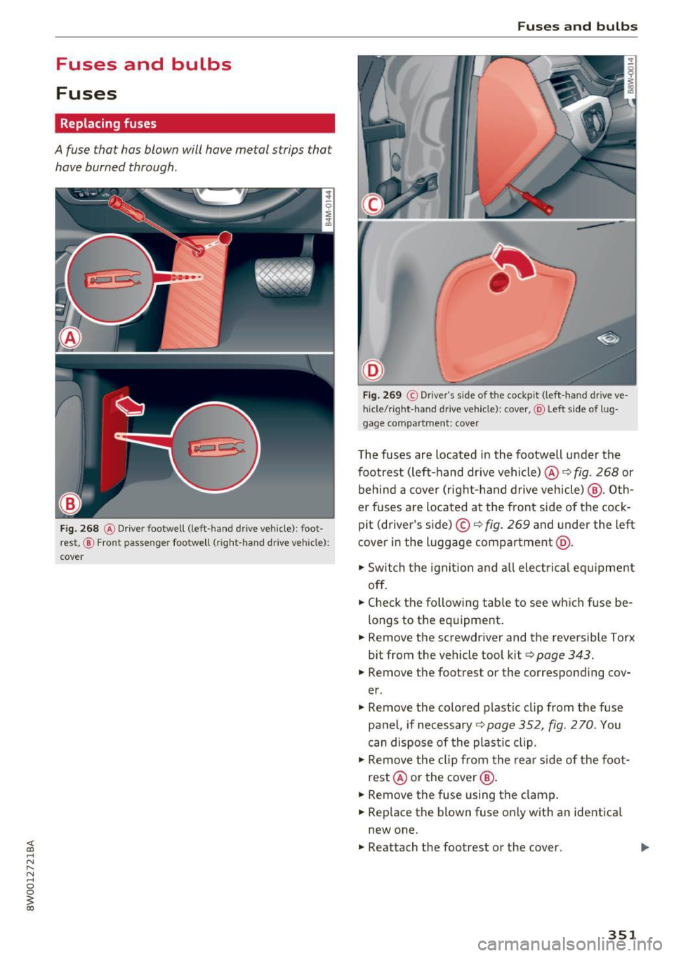
Fig. 268 @ Driver footwell (left -hand drive vehicle): foot
rest, @ Front passenger footwell (right-hand drive vehicle):
cover
Fuses and bulbs
D
Fig. 269 © Driver's s ide of the cockpit (left-hand drive ve·
hide/right-hand drive vehicle): cover, @ Left side of lug
gage compartment: cover
The fuses are located in the footwell under the
footrest (left-hand dr ive vehicle) @¢
fig. 268 or
behind a cover (right-hand drive vehicle) @ . Oth
er fuses are located at the front side of the cock
pit (driver's side) ©¢
fig. 269 and under the left
cover in the luggage compartment @.
.,. Switch the ignition and all electrical eq uipment
off .
.,. Check the fo llowing tab le to see which fuse be·
longs to the equipment .
.,. Remove the screwdriver and the reversible Torx
bit from the vehicle tool kit¢
page 343 .
.,. Remove the footrest or the corresponding cov
er .
.,. Remove the colored plastic cl ip from the fuse
pa nel, ifnecessary¢page352,
fig. 270 . You
can dispose of the plastic clip .
.,. Remove the clip from the rear side of the foot
rest @ or the cover@ .
.,. Remove the fuse using the clamp .
.,. Rep lace the blown fuse on ly with an identica l
new one .
.,. Reattach the footrest or the cover.
351
Page 354 of 386
Fuses and bulbs
Fuse color identification
Color Current rating
in amps
Black 1
Purple 3
Light brown 5
Brown 7.5
Red 10
Blue 15
Yellow 20
White or transparent 25
Green 30
orange 40
A WARNING
Do not repair fuses and never replace a blown
fuse with one that has a higher amp rating.
This can cause damage to the electrical sys
tem and a fire.
(D Note
If a new fuse burns out again shortly after you
have installed it, have the electrical system
checked as soon as possible by an authorized
Audi dealer or authorized Audi Service Facili
ty .
Q) Tips
-The following table does not list fuse loca
tions that are not used.
- Some of the equipment listed in the follow ing tables applies only to certain model ver
sions or certain optional equipment.
352
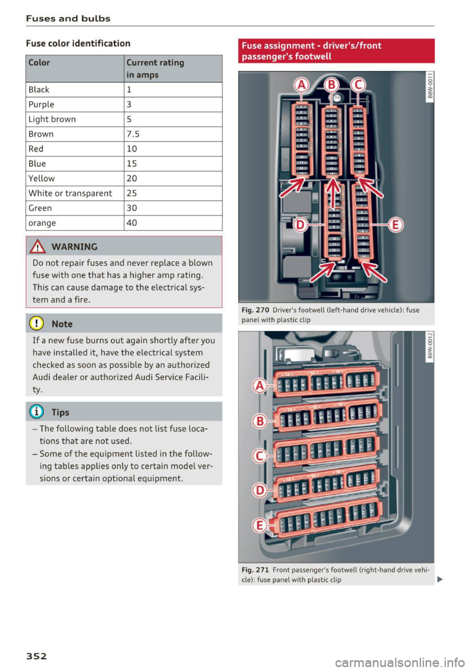
Fuse assignment - driver's/front
passenger's footwell
Fig. 270 D river 's footwell (left -hand drive vehicle) : fuse
panel w ith plastic clip
Fig. 271 Front passenger 's footwell (right -hand drive vehi-
cle) : fuse pa nel wit h plastic cl ip
Ill>
Page 355 of 386
<( a, .... N ,....
N .... 0 0
3 a,
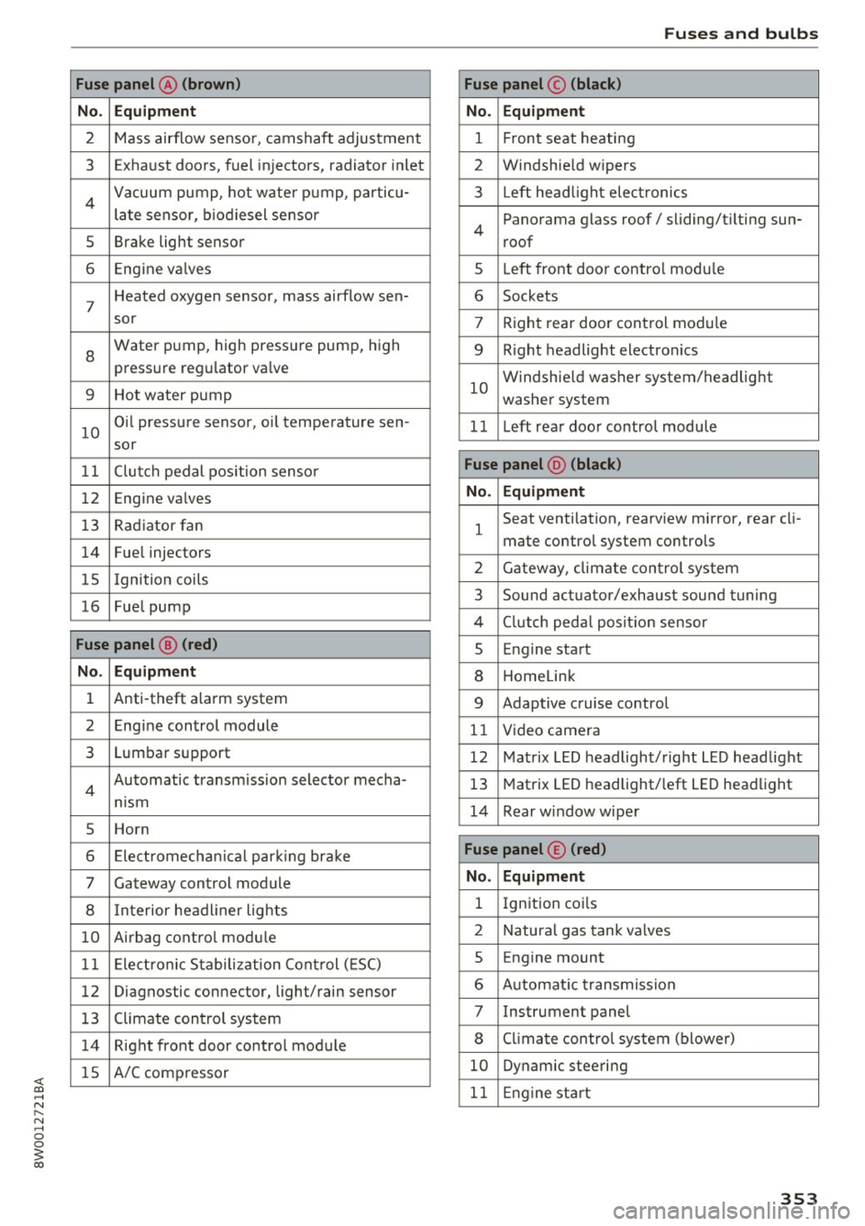
Fuse panel @ (brown)
No . Equipment
2 Mass airflow sensor, camshaft adjustment
3 Exhaust doors, fuel in jectors, radiator inlet
4 Vacuum pump, hot water pump, particu -
late senso r, biodiesel sensor
5 Brake light sensor
6 Engine va lves
7
Heated oxygen sensor, mass airflow sen-
sor
8
Water pump, high pressure pump, high
pressure regulator va lve
9 Hot water pump
10
Oil pressure sensor, oi l temperature sen-
sor
11 Clutch pedal position sensor
12 Engine valves
13 Radiator fan
14 Fuel injectors
15 I gnition coils
16 Fuel pump
Fuse panel @ (red)
No . Equipment
1 Anti-theft alarm system
2 Engine control module
3 Lumbar support
4
Automatic transmission selector mecha-
nism
5 Horn
6 Electromechan ical park ing brake
7 Gateway control module
8 I nterior headl iner lights
10 Airbag control module
11 Electronic Stabilization Control (ESC)
12 Diagnostic connector, light/rain sensor
13 Climate control system
14 Right front door control module
15 A/C compressor
Fuses and bulbs
Fuse panel © (black)
No . Equipment
1 Front seat heating
2 Windshield w ipers
3 L eft head light electronics
4
Panorama glass roof/ sliding/t ilting sun-
roof
5 L eft front door control module
6 Sockets
7 Right rear door control module
9 Right headlight electronics
10
Windshield washer system/headlight
washer system
1 1 Left rear door control module
Fuse panel @ (black)
No . Equipment
1
Seat ventilation, rearv iew mirror, rear cl i-
mate control system controls
2 Gateway , climate control system
3 Sound actuator/exhaust sound tuning
4 Clutch pedal pos ition sensor
s Engine start
8 Homelink
9 Adaptive cruise control
11 Video camera
12 Matrix LED headlight/right LED headlight
13 Matrix LED headlight/left LED headlight
14 Rear window wiper
Fuse panel © (red)
No . Equipment
l Ignition coi ls
2 Natural gas tank valves
5 Engine mount
6 Automat ic transmission
7 Instrument panel
8 Cli mate control system (blower)
10 Dynamic steering
11 Engine start
353
Page 356 of 386
Fuses and bulbs
Driver's side cockpit fuse assignment
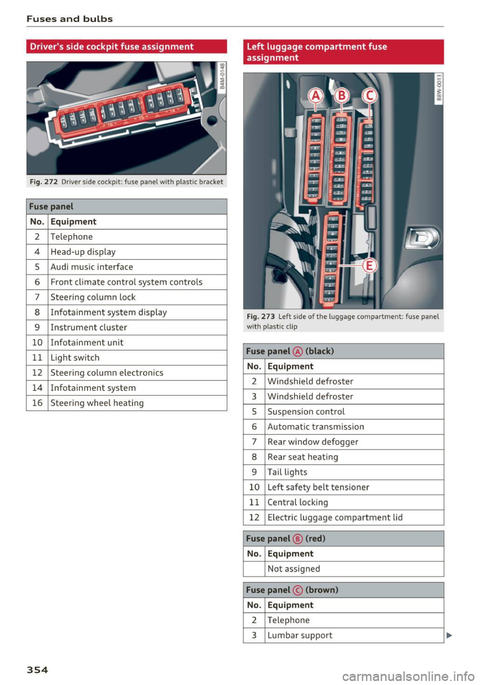
Fig . 27 2 Driver side cockpit: fuse panel with plastic bracket
Fuse panel
No . Equipment
2 Te lephone
4 Head-up display
5 Audi mus ic interface
6 Front cl imate co ntro l system co ntro ls
7 Steering column lock
8 Infota inment sys tem display
9 Instrument cl uster
10 Info ta inment unit
11 Light switch
12 Steering col umn elec tronics
14 Infotainment system
16 Steer ing wheel hea ting
354
left luggage compartment fuse
assignment
Fig. 27 3 Left side of the luggage compartment: fuse panel
w ith plastic clip
Fuse panel @ (black)
No. Equipment
2 Windshie ld defroster
3 W indshie ld defroste r
5 Suspension control
6 Automat ic t ransmiss io n
7 Rear window defogge r
8 Rear seat heat ing
9 Tail lights
10 L eft sa fety belt tensioner
11 Cent ral locking
12 E lectric luggage comp artment lid
Fuse panel ® (red)
No. Equipment
No t assigned
Fuse panel © (brown )
No. Equipment
2 Telephone
3 L umbar support
Page 357 of 386
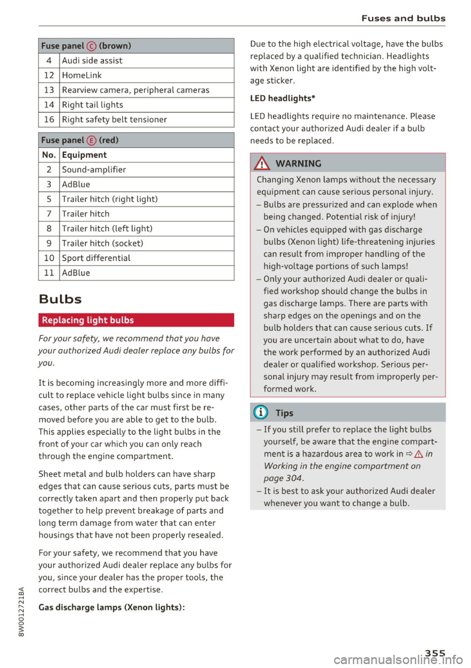
Fuse panel © (brown)
4 Audi side assist
12 Homelink
13 Rearview camera, peripheral cameras
14 Right tail lights
16 Right safety belt tensioner
Fuse panel © (red)
No. Equipment
2 Sound-amp lifier
3 Ad Blue
5 Trailer hitch (right light)
7 Trailer hitch
8 Trailer hitch (left light)
9 Trailer h itch (socket)
10 Sport differential
11 Ad Blue
Bulbs
Replacing light bulbs
For your safety, we recommend that you have
your authorized Audi dealer replace any bulbs for
you.
I t is becoming increasing ly more and more diffi
cult to replace vehicle light bulbs since in many
cases, other parts of the car must first be re
moved before you are able to get to the bulb.
This applies especially to the light bulbs in the
front of your car wh ich you can only reach
through the eng ine compartment.
Sheet metal and bulb ho lders can have sharp
edges that can cause serious cuts, parts must be
correctly taken apart and then properly put back
together to help prevent breakage of parts and
long term damage from water that can enter
housings that have not been properly resealed.
For your safety, we recommend that you have
your author ized Audi dealer replace any bulbs for
you, s ince your dealer has the proper tools, the
;;§ correct bu lbs and the expert ise .
.... N
~ Gas discharge lamps (Xenon lights): .... 0 0
3
Due to the high e lectrica l voltage, have the bulbs
replaced by a qualified technician. Headlights
with Xenon light are identified by the high volt
age sticker.
LED headlights*
LED headlights require no maintenance. Please
contact your authorized Audi dealer if a bulb
needs to be replaced.
& WARNING ~ -
Changing Xenon lamps without the necessary
equipment can cause serious personal injury.
- Bulbs are pressurized and can explode when
being changed . Potential risk of injury!
- On vehicles equipped with gas discharge
bu lbs (Xenon light) life-threatening injuries
can resu lt from improper handling of the
h ig h-vo ltage portions of such lamps!
- Only your authorized Audi dealer or quali
fied workshop shou ld change the bulbs in
gas discharge lamps. There are parts with
sharp edges on the openings and on the bulb holders that can cause serious cuts. If
you are uncerta in about what to do, have
the work performed by an authorized Audi deale r or qualified workshop. Ser ious per
sonal injury may result from improperly per
formed work.
(D Tips
-If you st ill prefer to replace the light bulbs
yourself, be awa re that the engine compa rt
ment is a hazardous area to work in~.&..
in
Working in the engine compartment on
page 304.
-It is best to ask your authorized Audi dealer
whenever you want to change a bulb.
355
Page 358 of 386
Emergency situations
Emergency situations
General
This chapter is intended for trained emergency crews and working personnel who have the nec
essary tools and equipment to perform these
operations.
Starting by pushing or
towing
CD Note
Vehicles with an automatic transmission
cannot be started by pushing or towing.
Starting with jumper
cables
If necessary, the engin e con be started by con
necting it to the battery of another vehicle.
If the engine should fail to start because of a dis
charged or weak battery, the battery can be con
nected to the battery of
another vehicle, using a
pair of jumper cables to start the engine.
Jumper cables
Use only jumper cables of sufficiently large cross
section
to carry the starter current safely. Refer
to the manufacturer's specifications.
Use only jumper cables with
insulated terminal
clamps which are distinctly marked :
plus(+) cable in most cases colored red
minus(-) cable
in most cases colored black.
A WARNING
Batteries contain electricity, acid, and gas.
Any of these can cause very serious or fatal in
jury. Follow the instructions below for
safe
handling of your vehicle's battery.
-Always shield your eyes and avoid leaning
over the battery whenever possible.
-A discharged battery can freeze at tempera
tures just below 32 °F (0 °C). Before con
necting a jumper cable, you must thaw the
356
frozen battery completely, otherwise it could explode.
- Do not allow battery acid to contact eyes or
skin. Flush any contacted area with water immediately.
- Improper use of a booster battery to start a
vehicle may cause an explosion.
- Vehicle batteries generate explosive gases.
Keep sparks, flame and lighted cigarettes
away from batteries.
- Do not try to jump start any vehicle with a
low acid level in the battery.
- The voltage of the booster battery must also
have a 12-Volt rating. The capacity (Ah) of
the booster battery should not be lower
than that of the discharged battery. Use of
batteries of different voltage or substantial
ly different "Ah" rating may cause an explo
sion and personal injury.
- Never charge a frozen battery. Gas trapped in the ice may cause an explosion.
- Never charge or use a battery that has been
frozen . The battery
case may have be weak
ened .
- Use of batteries of different voltage or sub
stantially different capacity (Ah) rating may
cause an explosion and injury. The capacity
(Ah) of the booster battery should not be
lower than that of the discharged battery.
- Before you check anything in the engine
compartment, always read and heed all
WARNINGS
~page 304.
CD Note
-Applying a higher voltage booster battery
will cause expensive damage to sensitive
electronic components, such as control
units, relays, radio, etc.
- There must be no electrical contact between
the vehicles as otherwise current could al
ready start to flow as soon as the positive
(+) terminals are connected.
@ Tips
The discharged battery must be properly con-
nected to the vehicle's electrical system. .,..
Page 359 of 386
When jump starting or charging the battery,
never connect the negative ground cable to
the battery negative post because the battery
manager system must be able to detect the
battery's state of charge . Always connect the
negative ground cable to the negat ive ground
post of the battery manager control unit .
Using the jump start
cable
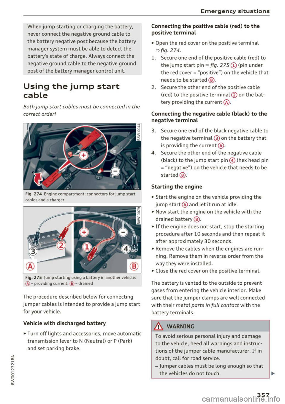
Both jump start cables must be connected in the
correct order!
Fig. 274 Engine co mpa rtment: connecto rs for jump start
cables and a charger
@
Fig. 275 Ju mp sta rting us ing a battery in another vehicle:
@ -providing cu rre nt, @ - drained
The procedure described below for connecting
jumper cables is intended to provide a jump start
for your vehicle.
Vehicle with discharged battery
.. Turn off lights and accessories, move automatic
transmission lever to N (Neutral) or P (Park)
and set parking brake .
Emergency situations
Connecting the positive cable (red) to the
po sitive terminal
.. Open the red cover on the positive terminal
r=>fig.274 .
1. Secure one end of the positive cable (red) to
the jump start pin
r=> fig. 275 (D (pin under
the red cover = "posit ive") on the vehicle that
needs to be started @.
2. Secure the other end of the pos itive cable
(red) to the positive termina l@ on the bat
tery provid ing the current @.
Connecting the negative cable (black) to the
negative terminal
3. Secure one end of the black negat ive cab le to
the negative terminal @on the battery that
i s p roviding the current@.
4. Secure the other end of the negative cable
(black) to the jump start pin@ (hex head pin
= "negative") on the vehicle that needs to be
started @.
Starting the engine
.. Start the engine on the vehicle providing the
jump start @and let it run at idle .
.. Now start the engine on the vehicle with the
drained battery @ .
.. If the engine does not start, stop the starting
procedure after 10 seconds and then repeat it
after approx imately 30 seconds .
.. Remove the cables when the engines are run
ning. Remove them in reverse order from the
way they were installed.
.. Close the red cover on the positive terminal.
T he battery is vented to the outside to prevent
gases from enter ing the vehicle interior . Make
s ur e that the jumper clamps are well connected
with their
metal ports in full contact with the
battery terminals.
_& WARNING
-To avoid serious personal injury and damage to the vehicle, heed all warnings and instruc
tions of the jumper cable manufacturer. If in
doubt, call for road service.
- Jumper cables must be long enough so that
the vehicles do not touch . ..,_
357
Page 360 of 386
Emergency situations
-When connecting jumper cables, make sure
that they cannot get caught in any moving
parts in the engine compartment.
- Do not bend over the batteries -danger of
chemical burns!
- The battery cell locking screws must be
tightened securely.
- Before you check anything in the engine
compartment, always read and heed all
WARNINGS
c> page 304.
(D Note
Improper hook-up of jumper cables can ruin
the generator.
- Always connect POSITIVE(+) to POSITIVE
(+), and NEGATIVE(-) to NEGATIVE(-)
ground post of the battery manager control
unit.
- Check that all screw p lugs on the battery
cells are screwed in firmly. If not, tighten
plugs prior to connect ing clamp on negative
battery terminal.
- Please note that the procedure for connect
i ng a jumper cable as described above ap
plies specifically to the case of your vehicle
being jump started . When you are giving a
ju mp start to another vehicle, do
not con
nect the negative (-) cable to the negative
(-) terminal on the discharged batte ry @
c> fig. 2 75. Instead, securely connect the
negative( -) cab le to either a solid metal
component that is firm ly bolted to the en
gine block or to the engine block itself. If
the battery that is being charged does not
vent to the outside, escap ing battery gas
could ignite and explode!
Towing with a tow truck
General hints
Your Audi requires special handling for towing.
The following information is to be used by com
mercial tow truck operators who know how to op
erate the ir equipment safely.
-Never tow your Audi, towing will cause dam
age to the engine and transmission.
358
-Never wrap the safety chains or winch cables
around the brake lines .
- To prevent unnecessary damage, your Audi
must be transported with a flat bed truck .
- To load the vehicle on to the flat bed, use the
towing loop found in the vehicle tools and at
tach to the front or rear anchorage
i:> page 358 and c> page 359 .
A WARNING
A vehicle being towed is not safe for passen
gers. Never allow anyone to ride in a vehicle
being towed, for any reason.
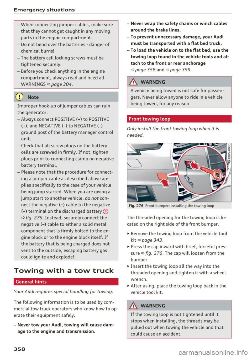
Front towing loop
Only install the front towing loop when it is
needed.
Fig. 276 Front bumper: installing the towing loop
The threaded opening for the towing loop is lo
cated on the right s ide of the front bumper.
.,. Remove the towing loop from the vehicle too l
ki t
c> page 343 .
.,. Press the cap inward with brief, forceful p res
sure
c> fig. 2 76. The cap will loosen from the
bumper .
.,. Insert the towi ng loop all the way into the
threaded opening and tighten it with a wheel
wrench.
.,. After using, place the towing loop back in the
vehicle tool kit .
A WARNING
If the towing loop is not tightened until it
stops when installing, the threads may be
pulled out when towing the vehicle and that
could cause an accident.
-