set clock AUDI A5 2008 8T / 1.G Owners Manual
[x] Cancel search | Manufacturer: AUDI, Model Year: 2008, Model line: A5, Model: AUDI A5 2008 8T / 1.GPages: 313, PDF Size: 12.13 MB
Page 15 of 313
Instruments and warning/indicator lamps13
Controls
Safety
Driving tips
General maintenance
Self-help
Technical data The button has the following functions:
Activating clock, date, temperature and mileage
recorder displays
The display will appear for about 30 seconds if you press the
button ⇒page 12, fig. 3 when the ignition is switched off.
Starting check procedure (auto-check control)
The auto-check control checks important components and vehicle
systems. These background checks are run constantly, as long as
the ignition is switched on ⇒page 29.
You can start the “check procedure” manually by pressing the
button with the ignition switched on. This function check can be
started at road speeds up to 5 km/h.
Calling up driver messages again
A red or yellow symbol appearing in the instrument cluster display
is normally accompanied by a corresponding message. The
message will disappear from the display after about 5 seconds. If
required, you can call up the message again by briefly pressing the
button.
Setting speed warning
You can press the button briefly to set speed limit warning 1
while the vehicle is moving ⇒page 28. If you press and hold the
button, this will cancel the speed warning.
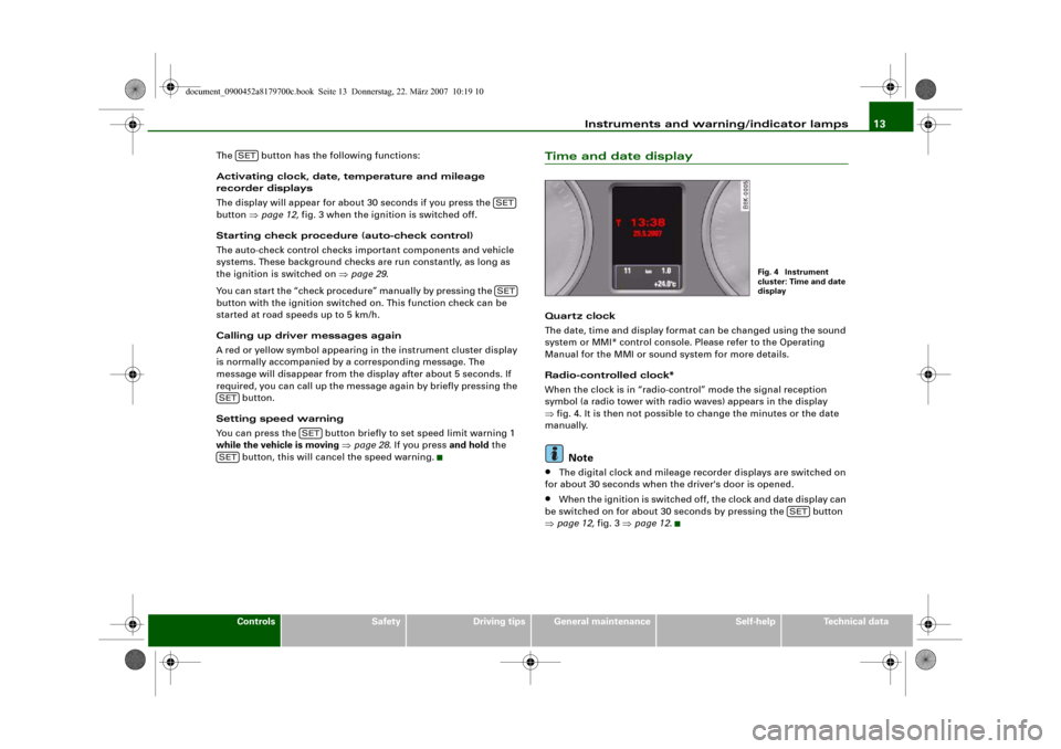
Time and date displayQuart z clock
The date, time and display format can be changed using the sound
system or MMI* control console. Please refer to the Operating
Manual for the MMI or sound system for more details.
Radio-controlled clock*
When the clock is in “radio-control” mode the signal reception
symbol (a radio tower with radio waves) appears in the display
⇒fig. 4. It is then not possible to change the minutes or the date
manually.
Note
•
The digital clock and mileage recorder displays are switched on
for about 30 seconds when the driver's door is opened.
•
When the ignition is switched off, the clock and date display can
be switched on for about 30 seconds by pressing the button
⇒page 12, fig. 3 ⇒page 12.
SET
SETSET
SET
SET
SET
Fig. 4 Instrument
cluster: Time and date
display
SET
document_0900452a8179700c.book Seite 13 Donnerstag, 22. März 2007 10:19 10
Page 16 of 313
Instruments and warning/indicator lamps 14Mileage recorder
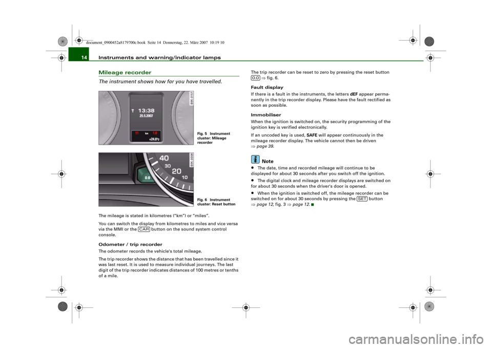
The instrument shows how far you have travelled.The mileage is stated in kilometres (“km”) or “miles”.
You can switch the display from kilometres to miles and vice versa
via the MMI or the button on the sound system control
console.
Odometer / trip recorder
The odometer records the vehicle's total mileage.
The trip recorder shows the distance that has been travelled since it
was last reset. It is used to measure individual journeys. The last
digit of the trip recorder indicates distances of 100 metres or tenths
of a mile.The trip recorder can be reset to zero by pressing the reset button
⇒fig. 6.
Fault display
If there is a fault in the instruments, the letters dEF appear perma-
nently in the trip recorder display. Please have the fault rectified as
soon as possible.
Immobiliser
When the ignition is switched on, the security programming of the
ignition key is verified electronically.
If an uncoded key is used, SAFE will appear continuously in the
mileage recorder display. The vehicle cannot then be driven
⇒page 39.
Note
•
The date, time and recorded mileage will continue to be
displayed for about 30 seconds after you switch off the ignition.
•
The digital clock and mileage recorder displays are switched on
for about 30 seconds when the driver's door is opened.
•
When the ignition is switched off, the mileage recorder can be
switched on for about 30 seconds by pressing the button
⇒page 12, fig. 3 ⇒page 12.
Fig. 5 Instrument
cluster: Mileage
recorderFig. 6 Instrument
cluster: Reset button
CAR
0.0
SET
document_0900452a8179700c.book Seite 14 Donnerstag, 22. März 2007 10:19 10
Page 59 of 313
Lights and vision57
Controls
Safety
Driving tips
General maintenance
Self-help
Technical data
– Turn the thumbwheel
⇒page 56, fig. 53 to the appro-
priate setting.
Adjustment settings
The settings correspond roughly to the following load conditions:
Two front occupants, luggage compartment empty
All seats occupied, luggage compartment empty
All seats occupied, luggage compartment loaded
Driver only, luggage compartment loaded
Caution
Always adjust the headlights to avoid dazzling oncoming traffic.
Make sure you lower the headlights when the vehicle is carrying a
heavy load.Instrument lighting
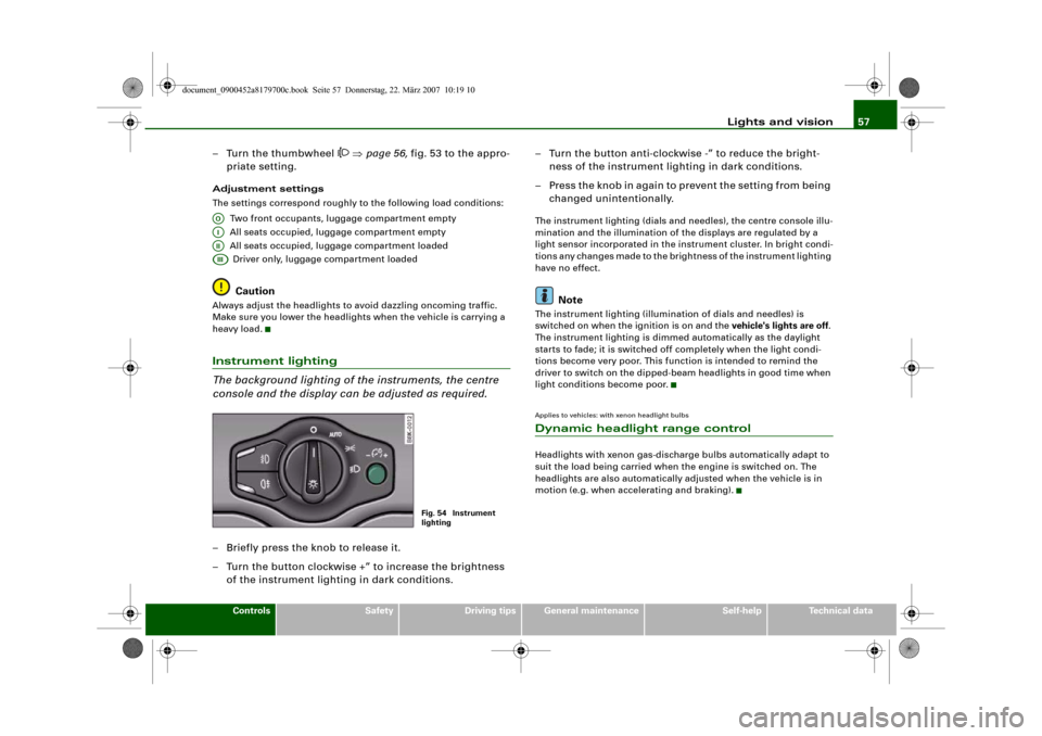
The background lighting of the instruments, the centre
console and the display can be adjusted as required.– Briefly press the knob to release it.
– Turn the button clockwise +” to increase the brightness
of the instrument lighting in dark conditions.– Turn the button anti-clockwise -” to reduce the bright-
ness of the instrument lighting in dark conditions.
– Press the knob in again to prevent the setting from being
changed unintentionally.
The instrument lighting (dials and needles), the centre console illu-
mination and the illumination of the displays are regulated by a
light sensor incorporated in the instrument cluster. In bright condi-
tions any changes made to the brightness of the instrument lighting
have no effect.
Note
The instrument lighting (illumination of dials and needles) is
switched on when the ignition is on and the vehicle's lights are off.
The instrument lighting is dimmed automatically as the daylight
starts to fade; it is switched off completely when the light condi-
tions become very poor. This function is intended to remind the
driver to switch on the dipped-beam headlights in good time when
light conditions become poor.Applies to vehicles: with xenon headlight bulbsDynamic headlight range controlHeadlights with xenon gas-discharge bulbs automatically adapt to
suit the load being carried when the engine is switched on. The
headlights are also automatically adjusted when the vehicle is in
motion (e.g. when accelerating and braking).
AOAIAIIAIII
Fig. 54 Instrument
lighting
document_0900452a8179700c.book Seite 57 Donnerstag, 22. März 2007 10:19 10
Page 98 of 313
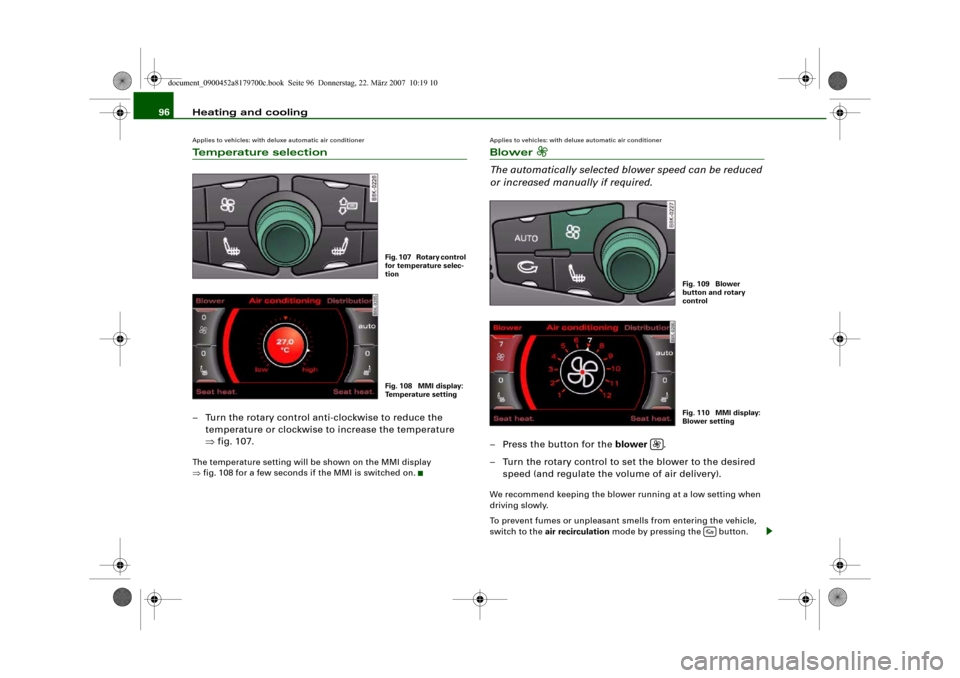
Heating and cooling 96Applies to vehicles: with deluxe automatic air conditionerTemperature selection– Turn the rotary control anti-clockwise to reduce the
temperature or clockwise to increase the temperature
⇒fig. 107.The temperature setting will be shown on the MMI display
⇒fig. 108 for a few seconds if the MMI is switched on.
Applies to vehicles: with deluxe automatic air conditionerBlower
The automatically selected blower speed can be reduced
or increased manually if required.– Press the button for the blower .
– Turn the rotary control to set the blower to the desired
speed (and regulate the volume of air delivery).We recommend keeping the blower running at a low setting when
driving slowly.
To prevent fumes or unpleasant smells from entering the vehicle,
switch to the air recirculation mode by pressing the button.
Fig. 107 Rotary control
for temperature selec-
tionFig. 108 MMI display:
Temperature setting
Fig. 109 Blower
button and rotary
controlFig. 110 MMI display:
Blower setting
document_0900452a8179700c.book Seite 96 Donnerstag, 22. März 2007 10:19 10
Page 107 of 313
Heating and cooling105
Controls
Safety
Driving tips
General maintenance
Self-help
Technical data
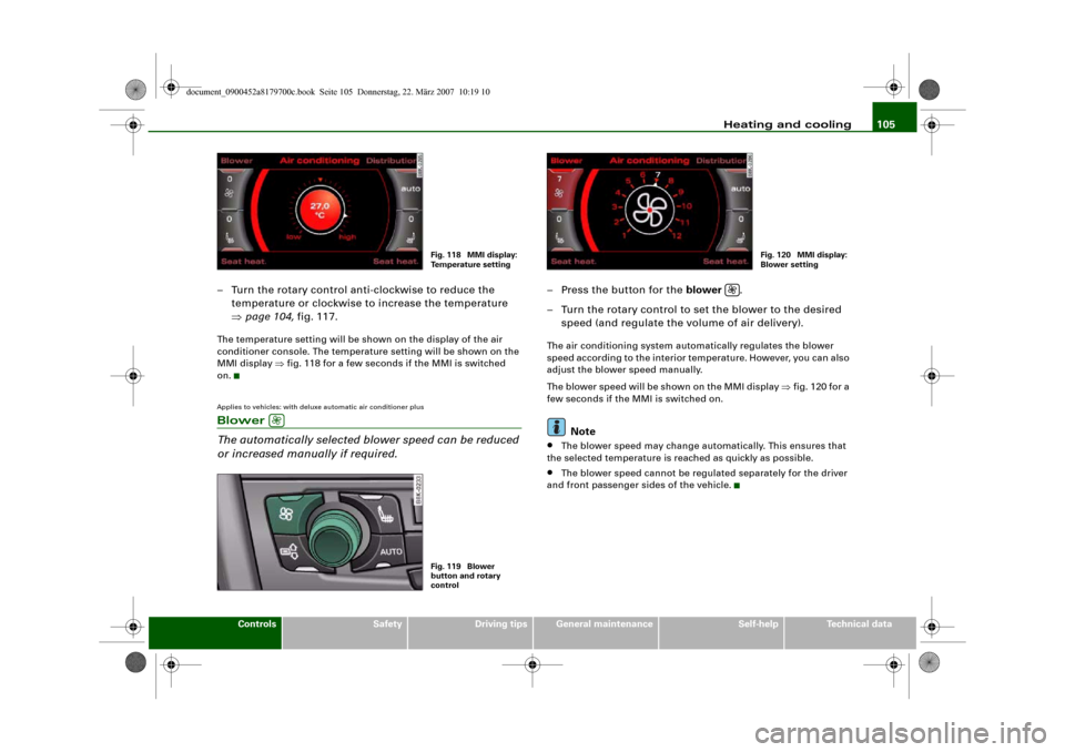
– Turn the rotary control anti-clockwise to reduce the
temperature or clockwise to increase the temperature
⇒page 104, fig. 117.The temperature setting will be shown on the display of the air
conditioner console. The temperature setting will be shown on the
MMI display ⇒fig. 118 for a few seconds if the MMI is switched
on.Applies to vehicles: with deluxe automatic air conditioner plusBlower
The automatically selected blower speed can be reduced
or increased manually if required.
– Press the button for the blower .
– Turn the rotary control to set the blower to the desired
speed (and regulate the volume of air delivery).The air conditioning system automatically regulates the blower
speed according to the interior temperature. However, you can also
adjust the blower speed manually.
The blower speed will be shown on the MMI display ⇒fig. 120 for a
few seconds if the MMI is switched on.
Note
•
The blower speed may change automatically. This ensures that
the selected temperature is reached as quickly as possible.
•
The blower speed cannot be regulated separately for the driver
and front passenger sides of the vehicle.
Fig. 118 MMI display:
Temperature setting
Fig. 119 Blower
button and rotary
control
Fig. 120 MMI display:
Blower setting
document_0900452a8179700c.book Seite 105 Donnerstag, 22. März 2007 10:19 10
Page 113 of 313
Heating and cooling111
Controls
Safety
Driving tips
General maintenance
Self-help
Technical data
Auxiliary heating and auxiliary
ventilationApplies to vehicles: with auxiliary heating - under development at the time of printingDescription
The auxiliary heating and ventilation systems heat and
cool the interior independently of the engine.The auxiliary heating
works in conjunction with the air condi-
tioner system, but does not rely on heat from the engine. Instead of
this, the system burns fuel. The system's main function is to warm
up the interior of the vehicle and to defrost the windows in cold
weather.
The auxiliary heating system can be used both when the vehicle is
stationary and when driving (to provide extra heat while the engine
is warming up).
The auxiliary ventilation also operates independently of the
engine. This feature can be used to cool the interior with the blower
when the vehicle is left parked in the sun.
The system will automatically activate either the auxiliary heating or
the auxiliary ventilation mode, depending on the actual tempera-
ture measured inside the car and the temperature you have set with
the air conditioner controls. It is possible to alter the temperature
setting while the auxiliary heating/ventilation is running.
Switching on and off
There are two different ways of switching on the auxiliary
heating/ventilation system.
•
Immediate start: You can switch the auxiliary heating/ventilation
on and off at any time in the MMI Car menu ⇒page 112. You can
also switch the system on and off using the remote control
⇒page 114.
•
Switching on via timer: You can programme various start times
using the timers ⇒page 112. However you must first activate the timer before the auxiliary heating/ventilation system will switch on
automatically.
The auxiliary heating/ventilation will switch itself off at the end of
the programmed running time. The running time can be set to 15,
30, 45 or 60 minutes ⇒page 113.
WARNING
•
The auxiliary heating must not be allowed to run when the
vehicle is in a confined space because it can give off toxic fumes.
•
To avoid any possible fire risk, never have the auxiliary heating
switched on when refuelling the vehicle.
•
Because of the high temperatures which occur when the auxil-
iary heating is running, make sure when parking the car that the
exhaust outlet under the car is not obstructed in any way and that
the exhaust gases do not come into contact with flammable mate-
rials (fire risk).Note
•
It is advisable to open the air outlets when using the auxiliary
heating/ventilation.
•
The auxiliary heating/ventilation will not switch on if the fuel in
the tank has reached the reserve zone.
•
The auxiliary heating/ventilation will not switch on if the battery
charge level is low.
•
The symbols
(auxiliary ventilation) or
(auxiliary heating)
flash in the instrument cluster next to the clock display when the
auxiliary heating/ventilation is switched on. Both symbols light
continuously when the timer is activated.
•
At low outside temperatures some visible water vapour may
form in the engine compartment. This is a normal phenomenon,
and no reason for concern.
document_0900452a8179700c.book Seite 111 Donnerstag, 22. März 2007 10:19 10
Page 114 of 313
Heating and cooling 112Applies to vehicles: with auxiliary heating - under development at the time of printingSwitching on/off immediatelySwitching on immediately
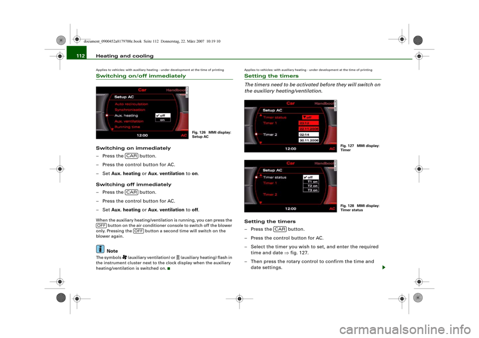
– Press the button.
– Press the control button for AC.
–Set Aux. heating or Aux. ventilation to on.
Switching off immediately
– Press the button.
– Press the control button for AC.
–Set Aux. heating or Aux. ventilation to off.When the auxiliary heating/ventilation is running, you can press the
button on the air conditioner console to switch off the blower
only. Pressing the button a second time will switch on the
blower again.
Note
The symbols
(auxiliary ventilation) or
(auxiliary heating) flash in
the instrument cluster next to the clock display when the auxiliary
heating/ventilation is switched on.
Applies to vehicles: with auxiliary heating - under development at the time of printingSetting the timers
The timers need to be activated before they will switch on
the auxiliary heating/ventilation.Setting the timers
– Press the button.
– Press the control button for AC.
– Select the timer you wish to set, and enter the required
time and date ⇒fig. 127.
– Then press the rotary control to confirm the time and
date settings.
Fig. 126 MMI display:
Setup AC
CARCAR
OFF
OFF
Fig. 127 MMI display:
TimerFig. 128 MMI display:
Timer status
CAR
document_0900452a8179700c.book Seite 112 Donnerstag, 22. März 2007 10:19 10
Page 215 of 313
Towing a trailer213
Controls
Safety
Driving tips
General maintenance
Self-help
Technical data
– Also check the shaft section of the ball joint and its asso-
ciated mechanical parts to make sure they are clean and
undamaged.Continued ⇒page 213, “Fitting the ball joint (step 2)”.
WARNING
It is important to keep the mounting fixture clean. Otherwise the
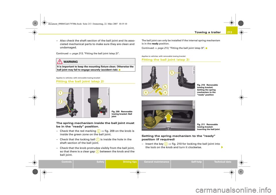
ball joint may fail to engage securely (accident risk).Applies to vehicles: with removable towing bracketFitting the ball joint (step 2)The spring mechanism inside the ball joint must
be in the "ready" position.
– Check that the red marking ⇒fig. 209 on the knob is
inside the green zone on the ball joint.
– Check that the locking ball is inside the hole in the
shaft section of the ball joint.
– Check that the knob protrudes visibly from the ball joint,
so that there is a clear gap between the knob and the
ball joint.
The ball joint can only be installed if the internal spring mechanism
is in the ready position.
Continued ⇒page 213, “Fitting the ball joint (step 3)”.Applies to vehicles: with removable towing bracketFitting the ball joint (step 3)Setting the spring mechanism to the "ready"
position (if required)
– Insert the key ⇒fig. 210 for locking the ball joint into
the lock on the knob and turn it clockwise.
Fig. 209 Removable
towing bracket: Ball
joint
A2A1A3
Fig. 210 Removable
towing bracket:
Setting the spring
mechanism to the
"ready" positionFig. 211 Removable
towing bracket:
Inserting the ball joint
A4
document_0900452a8179700c.book Seite 213 Donnerstag, 22. März 2007 10:19 10
Page 216 of 313
Towing a trailer 214
– Pull out the knob in direction , hold and turn in direc-
tion until the locking ball engages ⇒.
Inserting the ball joint
– With the spring mechanism in the “ready” position,
insert the ball joint into the mounting fixture and push it
upwards ⇒page 213, fig. 211 in the direction indicated
(arrow) ⇒. The spring mechanism should then
engage automatically with an audible click.
– Lock the ball joint by turning the key anti-clockwise.
– Take out the key and press the cover cap provided onto
the lock.Continued ⇒page 214, “Fitting the ball joint (step 4)”.
WARNING
•
If it is not possible to set the spring mechanism to the "ready"
position as described above, do not use the ball joint. Please take
your vehicle to a qualified workshop.
•
To avoid injury, keep your hands away from the knob and the
cover piece when inserting the ball joint into the mounting fixture.Note
Make sure that the knob can turn freely when the ball joint is
inserted.
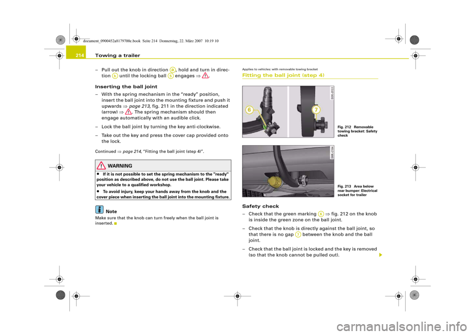
Applies to vehicles: with removable towing bracketFitting the ball joint (step 4)Safety check
– Check that the green marking ⇒fig. 212 on the knob
is inside the green zone on the ball joint.
– Check that the knob is directly against the ball joint, so
that there is no gap between the knob and the ball
joint.
– Check that the ball joint is locked and the key is removed
(so that the knob cannot be pulled out).
Aa
Ab
A5
Fig. 212 Removable
towing bracket: Safety
checkFig. 213 Area below
rear bumper: Electrical
socket for trailer
A6
A7
document_0900452a8179700c.book Seite 214 Donnerstag, 22. März 2007 10:19 10
Page 284 of 313
Fuses and bulbs 282
– Press the connector in the direction of the arrow
⇒page 281, fig. 267 until the bulb engages.
– Check that the bulb is securely seated in the bulb
housing.
– Fit the cover and swivel the retaining clip downwards.
– Install the headlight ⇒page 278.
– Check whether the new bulb is working.
– Have the headlight settings checked.Applies to vehicles: with xenon headlight bulbsChanging bulb for turn signalsThe bulb is secured in the bulb carrier with a bayonet
fastener.
– Remove the headlight ⇒page 278.
– Take off the rubber cap (small cover) and remove the bulb
carrier.
– Lightly press the defective bulb into the bulb carrier, then
turn it anti-clockwise and remove it.
– Do not touch the glass part of the new bulb with your
bare hands, use a cloth or paper towel instead.
– Fit the new bulb, pressing it into the bulb carrier, and turn
it clockwise as far as it will go.
– If necessary, use a cloth to remove any fingerprints from
the glass part of the bulb.
– Insert the bulb carrier into the headlight.Note
Ensure that the rubber cap is seated correctly so that no water can
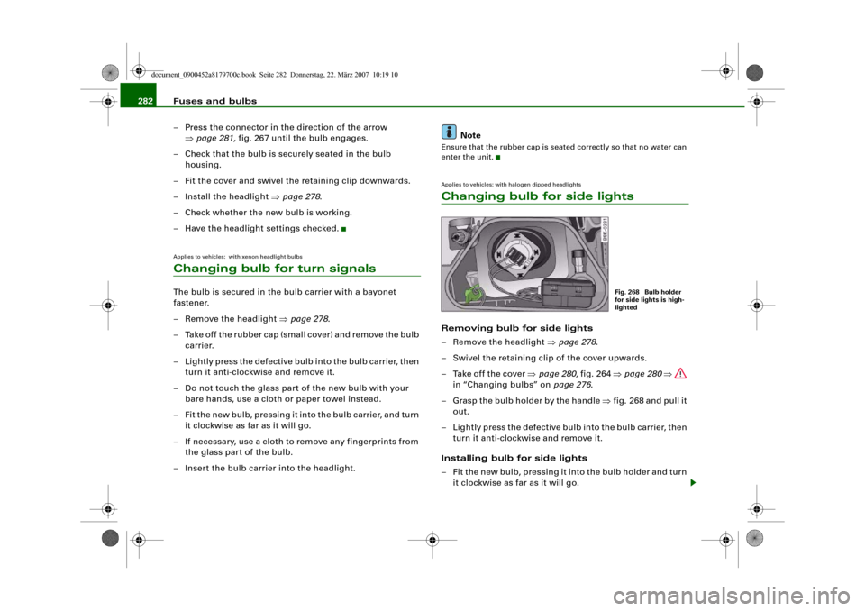
enter the unit.Applies to vehicles: with halogen dipped headlightsChanging bulb for side lightsRemoving bulb for side lights
– Remove the headlight ⇒page 278.
– Swivel the retaining clip of the cover upwards.
– Take off the cover ⇒page 280, fig. 264 ⇒page 280 ⇒
in “Changing bulbs” on page 276.
– Grasp the bulb holder by the handle ⇒fig. 268 and pull it
out.
– Lightly press the defective bulb into the bulb carrier, then
turn it anti-clockwise and remove it.
Installing bulb for side lights
– Fit the new bulb, pressing it into the bulb holder and turn
it clockwise as far as it will go.
Fig. 268 Bulb holder
for side lights is high-
lighted
document_0900452a8179700c.book Seite 282 Donnerstag, 22. März 2007 10:19 10