display AUDI A5 CABRIOLET 2011 Owners Manual
[x] Cancel search | Manufacturer: AUDI, Model Year: 2011, Model line: A5 CABRIOLET, Model: AUDI A5 CABRIOLET 2011Pages: 364, PDF Size: 86.48 MB
Page 4 of 364
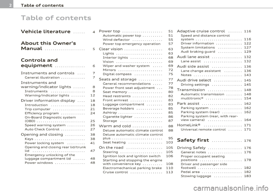
Table of contents
Table of contents
Vehicle literature ..... .
About this Owner's Manual ............. ...... .
Controls and
equipment .............. .
Instruments and controls ... .
General illustration ........... .
Instruments and
warning/indicator Lights ..... .
Instruments ................ .
Warning/indicator ligh ts ...... .
Driver information display ... .
Introduction ............ ... . .
Tri p com puter ......... ...... .
Eff iciency program ........... .
On-Board Diagnostic system (OBD) ....................... .
Speed warning sys tem ....... . .
Au to Check Control ........... .
Opening and closing ...... ... .
Keys ........... ... .......... .
Power locking system ........ .
Opening and closing rear lid/trunk
lid ....... ... ......... ...... .
Em erge ncy unlo cking of the
luggage compartment lid ..... .
Pow er windows ........ .. .. .. . 4
5
6
7
7
8
8
12
18
18
21
2 4
2S
26
27
38
38
41
47
48
48 Power top
............. ...... .
Automatic power top ......... .
Wind deflector .............. .
Power top emergency operat ion
Clear vision ............... ... .
Lig hts ....... ...... .... ... .. .
Interio r lights ............... .
Vis ion . ... ................ .. .
Wiper and washer system .... .
Mirror s .................. ... .
Digital compass ............ .
Seats and storage ........... .
G eneral recommendat ions .... .
Power front seat adjustment .. .
Seat memory ................ .
Head restrain ts .............. .
Front armrest ... .... ....... . .
Luggage compartment ....... .
Beverage holders ............ .
Ashtray ..................... .
Cigar ette lighter ......... .... .
S torage ............. ... .. .. .
Warm and cold .............. .
Delux e automatic climate control
Deluxe automatic climate control
p lu s ................... · · · · · ·
S eat heat ing .. .. ............ .
On the road ....... .......... .
Steer ing ................ ... . .
Ign it ion lock and ignition switch
Starting and stopping the engine
with conven ience ke y ........ . .
E lect romechanical parking brake
51
51
55
57
63
63
68
69
69 72
75
77
77
78
80
82
83
83
8S
8S
86
87
88
88
95
103
105
105
106
108
110
Cru ise control . . . . . . . . . . . . . . . . 113 Adaptive cruise control
116
Speed and distance control
system ............... ....... .
116
Driver informati on .......... ... 122
System limitation s ............ 127
Audi braking guard . . . . . . . . . . . . 129
Audi Lane assist ......... ...... 132
Lane assist ................... 132
Audi side assist ............... 136
Lane change ass istant ...... ... 136
No tes ...... ........ .......... 143
Audi drive select .............. 145
Driving settings ............... 145
T ransmission ........... ...... 148
Automatic transm iss ion . . . . . . . . 148
mult it ron ic® .. ................ 154
Park assist . . . . . . . . . . . . . . . . . . . . 162
Parking system . . . . . . . . . . . . . . . . 162
Park ing s ystem (rear) . . . . . . . . . . 162
Parking system (rear, with rear-
vi ew camera) . . . . . . . . . . . . . . . . .
164
Homelink ®
Universal remote control
171
171
Safety first . . . . . . . . . . . . . . . 17 6
D riving Safely ................. 176
Genera l notes . . . . . . . . . . . . . . . . . 176
Proper occupan t seating
posit ions . . . . . . . . . . . . . . . . . . . . .
178
Driver and passenger side
footwell . . . . . . . . . . . . . . . . . . . . . .
182
Pedal area . . . . . . . . . . . . . . . . . . . . 182
Stow ing luggage . . . . . . . . . . . . . . 183
Page 7 of 364
About this Owner's Manual
This owner's manual contains important information, tips, sugges
tions, and warnings for the use of your vehicle.
Make sure that this owner's manual is always located in the vehicle .
This is especially important if you allow other people to drive the
vehicle, or if you sell it.
This owner's manual describes the
equipment range specified for
this model at the editorial deadline date. Some of the equipment
described here will only be available at a later date, or only in specific
markets .
Some sections in this owner's manual do not apply to all vehicles. In
that case, the
range of applicability is given at the beginning of the
section, e. g., "Applies to vehicles: with Advanced Parking System". In
addition, optional equipment is indicated by an asterisk"*".
The details in the
illustrations may be different from those in your
vehicle, and are intended to be viewed as a basic guide.
You will find a
table of contents at the beginning of this book, which
displays all topics described in this manua l in order of appearance.
You will find an alphabetical
index at the end of this book.
All
directions , such as "left", "right", "front", "back", are relative to
the direction of travel.
* optional equipment
.,. This section continues on the next page.
• Indicates the
end of a section .
® Registered trademarks are identified with a®. If this symbol is
missing, it is no guarantee that the terms can be used freely.
=> & Cross-reference to a "WARNING!" within a section. For indica
tion with a page number, the corresponding "WARNING!" can be
found outside of the section .
Controls and equip
ment Safety first Vehicle operation
About this Owner's Manual
& WARNING
Text with this symbol
contains important information on safety
and how to reduce the risk of personal injury or death .
0 Note
Text with this symbol draws your attention to potential sources of
damage to you r vehicle.
ci' For the sake of the environment
Text with th is symbol contains information about the environment
and how you can help protect it.
[I) Tips
Text with this symbol contains spec ia l tips and other information
about getting the most out of your vehicle and its feat ures. •
Vehicle care Do-it-yourself service Technical data
Page 9 of 364
Instruments and controls
General illustration
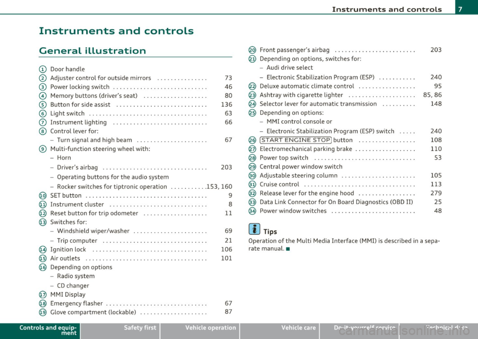
(D Door handle
@ Adjuster control for outside mirrors . . . . . . . . . . . . . . . 73
@ Power locking switch . . . . . . . . . . . . . . . . . . . . . . . . . . . . 46
© Memory buttons (driver's seat) . . . . . . . . . . . . . . . . . . . 80
® Button for side assist . . . . . . . . . . . . . . . . . . . . . . . . . . . 136
© Light switch . . . . . . . . . . . . . . . . . . . . . . . . . . . . . . . . . . . 63
0 Instrument lighting . . . . . . . . . . . . . . . . . . . . . . . . . . . . 66
@ Control lever for:
- Turn signal and high beam . . . . . . . . . . . . . . . . . . . . . 67
® Multi-function steering wheel with:
- Horn
- Driver's airbag . . . . . . . . . . . . . . . . . . . . . . . . . . . . . . . 203
-Operating buttons for the audio system
- Rocker switches for tiptronic operation ... .. ...... 153, 160
@ SET button . . . . . . . . . . . . . . . . . . . . . . . . . . . . . . . . . . . . 9
@ Instrument cluster . . . . . . . . . . . . . . . . . . . . . . . . . . . . . 8
@ Reset button for trip odometer . . . . . . . . . . . . . . . . . . . 11
@ Switches for:
- Windshield wiper/washer . . . . . . . . . . . . . . . . . . . . . . 69
- Tr ip computer .. .......... . .. .... .. .. .... ... .
@ Ignition lock ..... .. .................. ... .. ... .
@ Air outlets ........... ... .. ..... ... ........... .
@ Depending on options
- Radio system
- CD changer
@ MMI Display 21
106
101
@ Emergency flasher . . . . . . . . . . . . . . . . . . . . . . . . . . . . . . 67
@ Glove compartment (lockab le) . . . . . . . . . . . . . . . . . . . . 87
Controls and equip
ment Safety first
Instruments and controls
@ Front passenger
's airbag . . . . . . . . . . . . . . . . . . . . . . . . 203
@ Depending on options, sw itches for :
- Audi drive select
- Electronic Stabilization Program (ESP) . . . . . . . . . . . 240
@ Deluxe automatic climate control . . . . . . . . . . . . . . . . . 95
@ Ashtray with cigarette lighter . . . . . . . . . . . . . . . . . . . . 85, 86
@ Se lector lever for automat ic transmission . . . . . . . . . . 148
@ Depending on options:
- MMI control console or
- Electronic Stabilization Program (ESP) switch . . . . . 240
@ !START ENGINE STOP] button . . . . . . . . . . . . . . . . . 108
@ Electromechanical parking brake . . . . . . . . . . . . . . . . . . 110
@ Power top switch . . . . . . . . . . . . . . . . . . . . . . . . . . . . . . S3
@ Central power window switch
@ Adjustable steering column . . . . . . . . . . . . . . . . . . . . . . 105
@ Cruise control . . . . . . . . . . . . . . . . . . . . . . . . . . . . . . . . . 113
@ Release lever for the engine hood . . . . . . . . . . . . . . . . . 279
@ Data Link Connector for On Board Diagnostics (OBD II) 25
@ Power window sw itches . . . . . . . . . . . . . . . . . . . . . . . . . 48
[ i ] Tips
Operation of the Multi Media Interface (MMI) is described in a sepa
rate manual. •
Vehicle care Technical data
Page 10 of 364
Instruments and warning /indicator lights
Instruments and warning/indicator lights
Instruments
Instrument cluster and controls
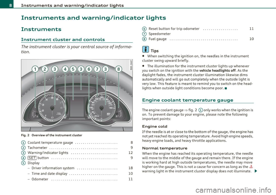
The instrument cluster is your central source of informa
tion .
Fig. 2 O ver view of the in strum ent cluster
© Coolant temperature gauge ......... .. .. ... ..... .
@ Tachometer ........ .... .. ... . .. .... ......... . .
® Warning/indicator light s ... .. .... .. . ... ... .. ... .
© [ SET] butto n ..... .. ... ..... ... ... .... ... . .. .. .
© Display
- Drive r information system .. .. .. ...... ........ .
- Time and da te dis play ... .. ... .... .. .. ... . .. .. .
8
9
12
9
18
10
- Odometer . . . . . . . . . . . . . . . . . . . . . . . . . . . . . . . . . . 11
© Reset button for trip odometer ................. .
0 Speedometer
@ Fu el g auge ...... .. .. ... . .. ... ... . ..... .... .. .
[ i ] Tips
• When swit ch ing the ign ition on, the need les in the instrument
cl uste r sw ing upward briefly .
11
10
• The illuminat ion for the instrument clu ster light s up whenever
you switch on the ignition with the
vehi cle headlights off . As the
daylight fades, the instrument cluster illum ination likewise dim s
au toma tic ally and w ill go ou t comple tely when the ou tside ligh t is
very low . Th is feature is meant to remi nd you to switch on the head
lights wh en outside lig ht conditions b ecom e poor .•
Engine coolant temperature gauge
T he e ngine coo la nt gauge ~ fig. 2 © only works whe n the ignition is
on . To prevent damage to your engine, please note the following
important po ints:
Engine cold
If the needle is a t or cl ose to the bottom of the gauge, the engine h as
not yet reached its operat ing temperature. Avoid high eng ine speeds,
heavy eng ine loads, and heavy th rott le applica tions.
Normal temperature
W hen the eng ine has reached its operati ng tem perature, the needle
w ill move to the midd le of the gauge and rema in there. If the engine
is working ha rd at hig h ou tside temperat ures, the nee dle may move
higher on the gauge. Th is is not a cause for concern as long as the-~
wa rning lig ht in t he instr ument clus ter display does not i llumina te. _.,,
Page 11 of 364
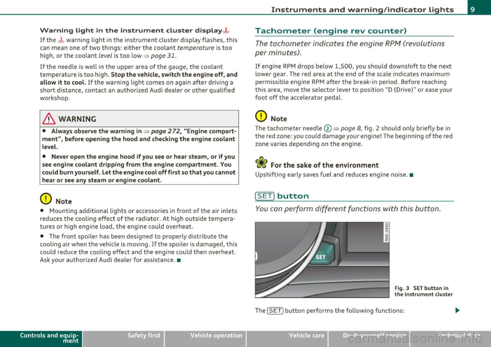
Warning light in the instrument cluster display-1-
If the _L warning light in the i nstrument clus ter display flashes, this
can mean one of two things: either the coo lant
temperature is too
high, or the coolant
level is too low ~ page 31 .
If the needle is well in the uppe r area of the gauge, the coo lant
temperature is too high.
Stop the vehicle, switch the engine off, and
allow it to cool.
If th e war ning light comes o n ag ain af ter driv ing a
short distance, contact an author ized Aud i dea ler or othe r qualified
wor ksh o p.
& WARNING
• Alway s observe the warn ing in :::} page 272, "Engine compart·
ment ", before opening the hood and checking the engine coolant
level.
• Never open the engine hood if you see or hear steam, or if you
s ee engin e coolant dripping from the engine compartment. You
could burn yourself . Let the engine cool off first so that you cannot
hear or see any steam or engine coolant .
0 Note
• Mounting add ition al lights o r accesso ries in fron t of the a ir inlets
reduces the cooling effect of the radiator . At high outside tempera
tur es o r high engine load, the eng ine could ove rhe at.
• The front spo iler has been designed to properly d istribute the
c oo lin g air when the vehicle is moving. If the sp oi ler is d amaged, this
co uld reduce the cooling eff ect and the eng ine could then overheat .
Ask your au thor ized A udi dealer for assis tance .•
Con tro ls a nd e quip
m en t Vehicle
OP-eration
Instruments and warning /indicator lights
Tachometer (engine rev counter)
The tachomete r in dic ates t he engine RPM (revoluti ons
pe r mi nutes) .
If engine RPM drops below 1,500, you shou ld downsh ift to the next
lower ge ar. T he red area at the end of the s cale i ndi cates max imum
permissible engine RPM after the brea k-in per iod. Before reaching
t his area, move t he selector lever to po sition "D (Dr ive)" or ease yo ur
foot off t he accelerator pedal.
0 Note
T he tachometer needle @~ page 8, fig. 2 should o nly br iefly be in
t he red zone: yo u co uld damage your eng ine! T he beg inning of the red
zone varies depe nd ing o n the eng ine.
~ For the sake of the environment
Upshifting early saves fuel and redu ces engine noise .•
[S ET] button
You c an per form d iffere nt fu nctions with t his but ton.
Fig . 3 SET butto n in
the instrume nt clu ste r
Th e !SE TI bu tto n performs the fo llow ing f unct io ns:
Vehicle care Do-it-yourselt service iTechnical data
Page 12 of 364
Instruments and warning/indicator lights
Switching on time , date, temperature display , and
odometer
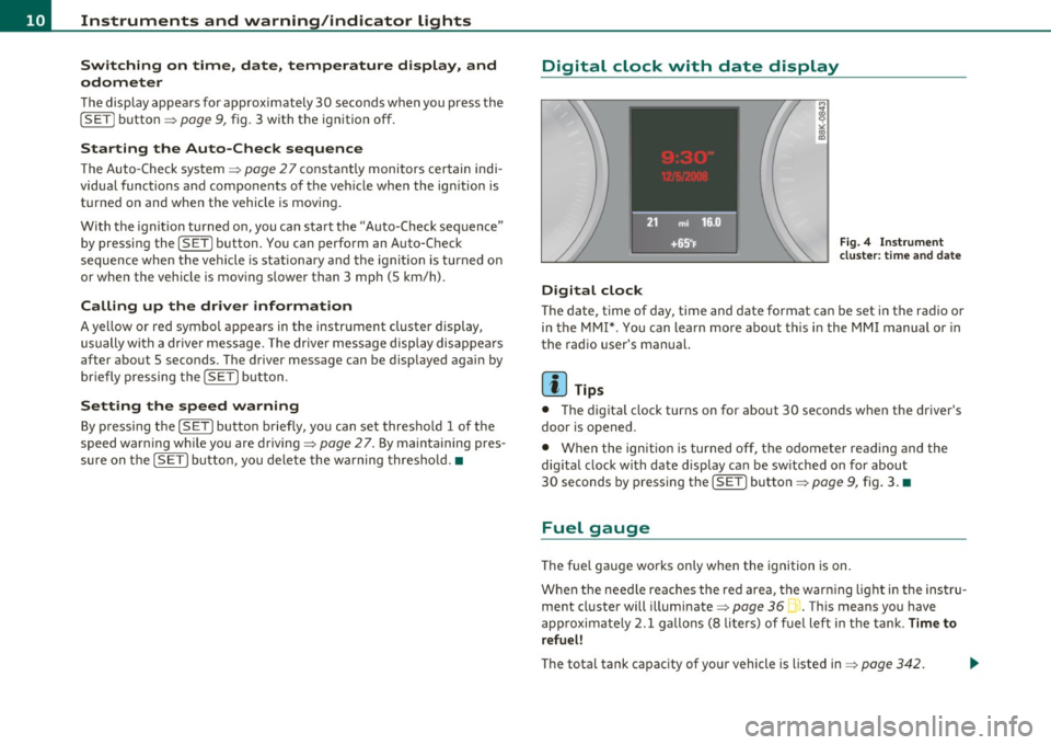
Th e display appears for approx imately 30 seconds w hen you press the
ISE Tj button => page 9, fig. 3 with t he ign it ion off.
Starting the Auto-Check sequence
T he Auto -Check system => page 27 constant ly monitors certain indi
vidua l func tions a nd components of the ve hicle whe n the ign ition is
t u rne d on and w hen the vehicle is mov ing.
Wi th the ignit ion turned o n, you can star t the "A uto -Check sequence"
by pressing the
! SET ] button . You can perfo rm an Auto-Check
sequence when the veh icle is station ary an d the ig niti on i s turned o n
or w hen the veh icle is mov ing slower t han 3 mp h (5 km/h).
Calling up the dr iver information
A ye llow or red symbol appears in the instr ument cluster display,
u su ally wi th a drive r message. T he drive r mes sage disp lay disappea rs
after about 5 seconds. The driver message can be d isp layed aga in by
br ie fl y pr essing the
!S ET ] button.
Setting the speed warning
By press in g t he I SE T] bu tton br iefly, yo u ca n set thres ho ld 1 of the
speed warn ing wh ile yo u are driving =>
page 27. By maintaining pres
su re on t he
!SE TI but ton , you dele te the w arning thres ho ld. •
Digital clock with date display
Digital clock
Fig. 4 Instrume nt
clu ster: t ime an d date
T he date, t ime of day, time and date format can be set in the rad io o r
in the MMI* . You can learn more about this in the MMI manual or in
the radio user's man ual.
[ i ] Tips
• Th e digita l clock turns on for about 30 secon ds w hen the dr iver's
door is opened.
• When the ignition is turned off, the odometer rea ding and the
dig ital clock with date display can be sw itched on for about
30 seconds by press ing the
[ SET I butto n=> page 9, fig. 3. •
Fuel gauge
The f uel gauge wo rks on ly when the ignition is on.
W hen the nee dle rea che s the red a rea, the war ning ligh t in t he ins tru
ment cl uster will illuminate =>
page 361 ,. Th is means you have
a p pr oxi mate ly 2.1 gallons (8 liters) of f uel left in t he ta nk .
Time to
r efuel!
T he total tank capac ity of yo ur vehicle is liste d in => page 342. .,,
Page 13 of 364
0 Note
Never run the tank completely d ry! An irregular supply of f uel can
cause engine misfiring and fuel could enter into the exhaust system.
T he ca talyt ic conver ter could then overhea t and be damaged. •
Odometer
The odometer indicates the distance driven.
Fi g. 5 Ins tru m ent
cl uster : odome ter
Fig . 6 Instrume nt
cl uster : reset button
The disp lay of distance driven is s hown in kilometers "km" or i n
"miles" .
• USA models - Miles
• Canada models -Kilomete rs
Con tro ls a nd e quip
m en t Vehicle
OP-eration
Instruments and warning /indicator lights
The un its of measure (k ilomete rs/miles) can be changed in the MMI
or us ing the [
CAR] button on the r adio con trol.
Odometer /trip odometer
T he odomete r sh ows the tot al number of kilomete rs or mile s tha t
have been driven on the vehicle.
Th e tr ip odomete r shows the distance dr iven si nce it was last reset.
It
can be used to measure short d istances. The last d ig it shows
distances of 100 meters or 1/10 of a m ile.
Th e trip odome te r c an be reset to zero by pressi ng the reset bu tton
[O.O) ~ fig. 6.
Malfunction message
If there is a ma lf u nction somewhere in the instrument cluster, dEF
will appear in th e trip odomet er and w ill stay on. Conta ct you r au tho
rized Aud i dea le r to have the p roblem corrected.
Immobilizer
Whe n the ignition is switched o n, the data on the ignition key are
scanned automati cally.
If an unauthorized key was used,
SAFE is display ed permanently in
t he o dome ter display field. The vehicle ca nnot be o per ated
~ page 38.
[ i ] Tips
• T he date, t ime, and distance continue to show for about 30
seconds after the igni tion is switched off .
• The odometer turns on for about 30 seconds w hen the driver's
door is opened.
• The odometer can be turned on for approximately 30 seconds
with the igni tion of f by pres sing the [S ET] button ~
page 9, fig. 3 . •
Vehicle care Do-it-yourselt service iTechnical data
Page 15 of 364
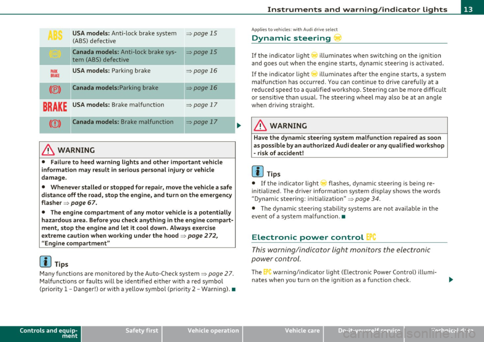
USA models: Anti-lock brake system ~ page 15
(ABS) defective
Ca nada models : Anti-lock brake sys-~ page 15
tern (ABS) defective
PARK USA models: Parki ng b rake ~ page 16
BRAKE
(® ) Canada models: Parking brake ~ page 16
BRAKE USA models: Brake malfunction ~ page 17
(Q) ) Canada mode ls : Brake malfunction ~ page 17
----·-
& WARNING
• Failure to heed warning light s and other important vehicle
information may result in serious personal injury or vehicle
damage .
• Whenever stalled or stopped for repai r, move the vehicle a safe
di stance off the road, stop the engine, and turn on the emergency
flasher ~
page 67.
• The engine compartment of any motor vehicle i s a potentially
hazardous area. Before you check anything in the engine compart
ment, stop the engine and let it cool down . Always exercise
e x treme caution when wor king under the hood~
page 2 72 ,
"Engine compartment "
[I] Tips
Many f unct io ns ar e mon itored by the Auto-Chec k system ~ page 27.
Ma lfu nctions or faults w ill be identified eithe r with a red symbol
(pr io rit y
1 -Danger!) or with a ye llow symbol (priori ty 2 -War ning). •
Controls and equip
ment Safety first
Instruments and warning
/indicator lights
App lies to ve hicles : w ith Au di dr ive select
Dynamic steering
If the ind ic a tor light () illumina te s w hen swi tching on t he ig nition
and goes ou t when the engine starts, dynamic steering is activated.
If the ind icator light
r ill uminates after the engine sta rts, a system
ma lfunct ion has occurred . Yo u can co ntinue to drive caref ully at a
re duced speed to a qualified workshop. Steering can be more diffic ult
or sensit ive tha n usual. The stee ring w heel may a lso be at an angle
when driving straight.
& WARNING
Have the dynamic steering sy stem malfunction repaired as soon
as possible by an author ized Audi d ealer
or any qualified workshop
- risk of accident!
[ i ] Tips
• If the indicator light ~ flashes, dynamic stee ring is being re
initialized. The d river info rmation system display shows the words
"Dynamic steering : initiali zation" ~
page 34.
• The dy namic steering stab ility systems a re not availab le in the
event of a system ma lfunction .•
Electronic power control '
This warning/indicator Light monitors t he electronic
pow er control .
The C'., warning/indicator light (E lectronic Powe r Cont rol) illumi
nates when you turn o n the ignition as a function check .
Vehicle care Technical data
Page 19 of 364
• If the slope of the ground is too steep to park the ve hicle, the addi
tional d rive message appears
Caution: Vehicle parked too steep .
• In the event of a parking brake malfunction, the ye llow symbol
appea rs in the ins trument cl uster d isp lay and the driver message
Parking brake malfunction! is displayed . Have the malfunction
repaire d as soon as possible by an au thori zed A udi dealer o r any o ther
qualified workshop .•
Brake system BRAKE (USA
models)
/ (CD) (Canada models)
The warning/indi cat or li ght flas hes if brake fluid le vel is
lo w, if there is an AB S syst em malf unctio n or a parki ng
brak e malfunction.
Th e light illum inates w he n th e ignition is turned on. It goes out after
the engine has been started . This indicates that the brake war ning
light is functioning properly.
If the brake warning light does not light up when the engine is
cranking , there may be a malfunct ion in the electr ical system. In
this ca se, contact an authorized Audi dealer.
If the brake system warning/ind icator light flashes, there is a brake
system malfunction. By press ing the [SET ] button, you can bring up a
dr iver message w hich expl ains the ma lfun ct io n in more deta il
:::>page 30.
If the A BS fails, t he A BS warn ing/ indi cato r light ....
s., (U SA
mode ls)/ (Canada mode ls) flashes together with the brake system
wa rning/indica tor ligh t==> & .
(USA models):
If the wa rning lig ht BRAKE and the warn ing l ight f'l ill u
minate together, immediate ly contact your author ized Audi dealer or
qualif ied wo rkshop to have all bra ke pads inspected::::>
page 35.
When the light comes on, an audible warn ing signal is also given.
Controls and equip
ment Safety first
Instruments and warning
/indicator lights
& WARNING
• USA models: If the BRAKE warning light and the I warning
light come on together, the rear wheel s could lock up first under
hard braking . Rear wheel lock-up can cause loss of vehicle control
and an accident. Have your vehicle repai red immediately by you r
authorized Audi dealer or a qualified workshop. Drive slowly and
avoid sudden, hard brake applications.
• Canada models : If the brake warning light ((j)) and the ABS
warning light
~ come on together , the rear wheels could lock up
first under hard braking . Rear wheel lock-up can cause loss of
vehicle control and an accident. Have your vehicle repaired imme
diately by your authorized Audi dealer or a qualified workshop .
Drive slowly and avoid sudden , hard brake applications.
• If the brake warning /indicator light does not go out after a few
second s and the parking brake released , or lights up while you are
driving , the fluid level in the brake fluid reservoir i s too low. If you
believe that it is safe to do so , proceed immediately at low speed
to the neare st authorized Audi dealer or qualified repair facility
and have the brake system inspected .
• Always keep in mind that after several brake applications, you
will need greater pressure on the brake pedal to stop your vehicle.
Do not rely on strained brake s to re spond with maximum stopping
power in critical situations. You must allow fo r increased braking
di stan ce s. The extra distance used up by fading brakes could lead
to an accident. •
Vehicle care Technical data
Page 20 of 364
Driver information display
Driver information display
Introduction
General notes
The driver information display inside the instrument
cluster provides you, the driver, with much useful infor
mation.
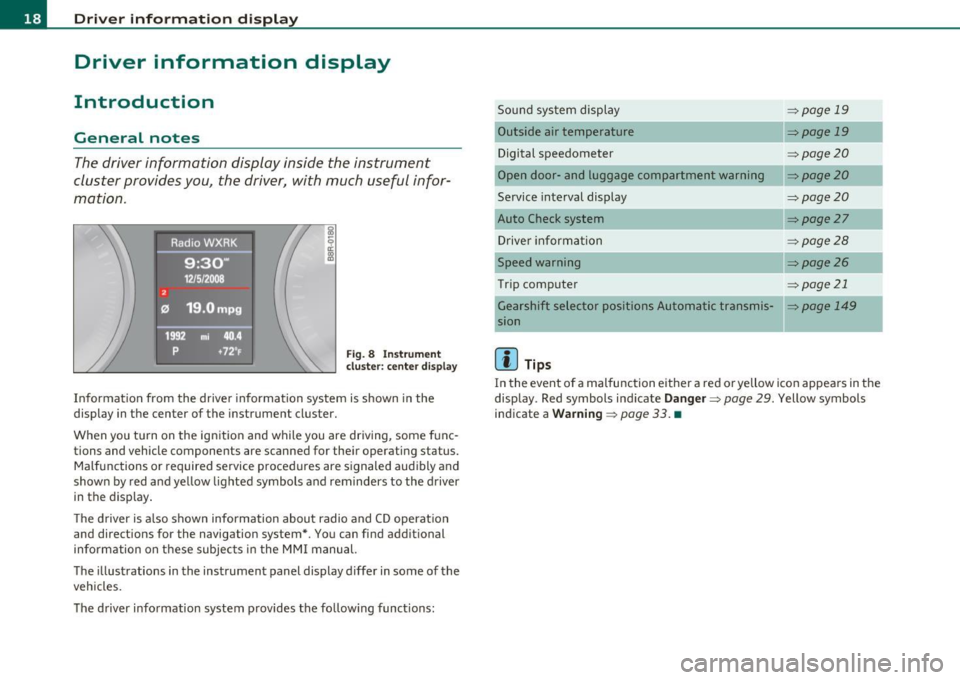
Fig. 8 Instrument
cluster: center display
Information from the driver information system is shown in the
display in the center of the instrument cluster.
When you turn on the ignition and while you are driving, some func
tions and vehicle components are scanned for their operating status. Malfunctions or required service procedures are signaled audibly and
shown by red and yellow lighted symbols and reminders to the driver
in the display.
The driver is also shown information about radio and CD operation
and directions for the navigation system*. You can find additional
information on these subjects in the MMI manual.
The illustrations in the instrument panel display differ in some of the
vehicles.
The driver information system provides the following functions: Sound system display
Outside air temperature
Digital speedometer
Open door- and luggage compartment warning
Service interval display
Auto Check system
Driver information
Speed warning
Trip computer
------- ---.,
::>page 19
=>page 19
=> page20
::> page20
=>page20
=> page27
=> page28
=>page26
=> page21
_ _.
Gearshift selector positions Automatic transmis-=> page 149
sion
[I] Tips
In the event of a malfunction either a red or yellow icon appears in the
display . Red symbols indicate
Danger=> page 29. Yellow symbols
indicate a
Warning => page 33. •