AUDI A5 COUPE 2011 Owners Manual
Manufacturer: AUDI, Model Year: 2011, Model line: A5 COUPE, Model: AUDI A5 COUPE 2011Pages: 362, PDF Size: 84.88 MB
Page 321 of 362
_____________________________________________ W __ h....:a_ t ___ d_o ___ I_ d_o :.....:.. n.:..o::.. w.:....:.. ?------J-
& WARNING (continued)
• Do not loosen the wheel bolts more than one turn before you
raise the vehicle with the jack. -You risk an injury.
(I) Tips
• Never use the hexagonal socket in the handle of the screwdriver to
loosen o r tighten the wheel bolts .
• If a wheel bolt is very tight, you may find it easier to loosen by
carefully pushing down on the end of th e wheel bolt wrench with
one
foot only .
As you do so, hold on to the car to keep your balance and
take ca re not to slip .•
Raising the vehicle
The vehicle must be li~ed with the jack first before the
wheel can be removed.
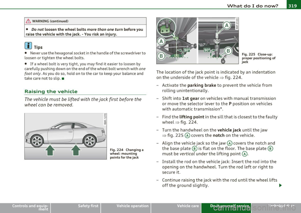
•
Fig. 224 Changing a
wheel: mounting
points for the jack
Vehicle OP-eration
Fig. 225 Close-up:
proper positioning of
jack
The location of the jack point is indicated by an indentation
on the underside of the vehicle=> fig. 224.
- Activate the
parking brake to prevent the vehicle from
rolling unintentionally.
- Shift into
1st gear on vehicles with manual transmission
or move the selector lever to the
P position on vehicles
with automatic transmission*.
- Find the
lifting point in the sill that is closest to the faulty
wheel => fig. 224.
Turn the handwheel on the
vehicle jack until the jaw
=> fig . 225 @ covers the
notch on the vehicle.
- Align the vehicle jack so the jaw@ covers the notch and
the base plate @ is flat on the floor. The base plate @
must be
vertical under the lifting point@.
- Install the rod on the vehicle jack: Insert the rod into the
opening on the handwheel. Turn the rod left or right to
secure it.
- Continue raising the jack with the rod until the wheel lifts
off the ground slightly. ..,_
Vehicle care Do-it-yourself service iTechnical data
Page 322 of 362
lffl!l.,___W __ h_a_ t_ d_ o_ I_ d_o_ n_ o_w _ ? _____________________________________________ _
Only position the veh icle jack at the designated points=> page 319,
fig . 224 . Th ere i s ex act ly
one loc ation for each whee l. Do not position
the jac k in any othe r locations .
Soft ground under the jack can cause the vehicle to slip
off the jack.
Alw ays p lac e the j ack on firm ground . U se a fla t, stab le s uppor t if
necessary. Use a non -s li p surface s uch as a ru bber mat on a slippery
surface such as ti le.
& WARNING
• You or your passengers could be injured while changing a
wheel if you do not follow these safety precautions :
- Positioning the jack under the vehicle at any other place than
those indicated above may damage the vehicle or may result in personal injuries.
- A soft or unstable surface under the jack may cause the
vehicle to slip
off the jack. Always provide a firm base for the
jack on the ground.
If necessary, use a sturdy board under the
jack.
- On hard, slippery surface (such as tiles) use a rubber mat or
similar to prevent the jack from slipping.
• To help prevent injury to yourself and your passengers: -Do not raise the vehicle until you are sure the jack is securely
engaged.
- Passengers must not remain in the vehicle when it is jacked
up .
- Make sure that passengers wait in a safe place away from the
vehicle and well away from the road and traffic.
- Make sure jack position is correct, adjust as necessary and
then continue to raise the jack. •
Taking the wheel off/installing the spare
tire
Follow these instr u ction s step- by -s tep for chan ging th e
w heel .
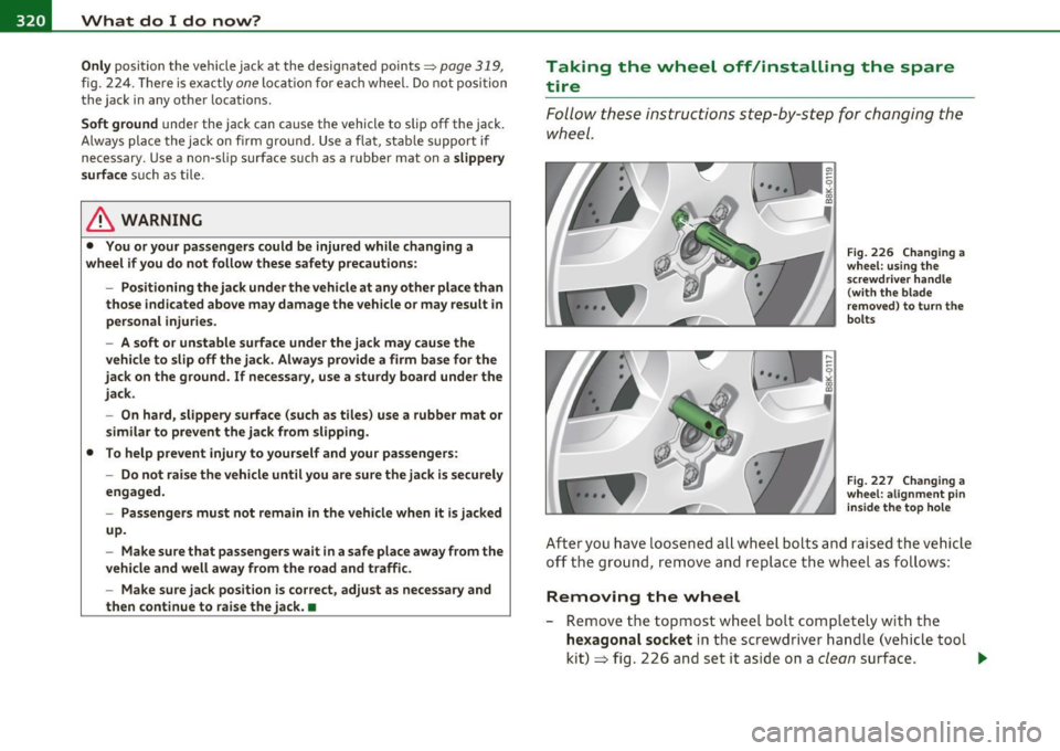
Fig. 226 Changing a
wheel : using the
s crewdriver handle
( with the blade
removed ) to turn the
bolts
Fig. 227 Changing a
whee l: alignment pin
in side the top hole
Aft er yo u have L oosened a ll w hee l bolts and r aise d the v ehicle
off th e ground, remo ve and rep lace t he whe el as fo llows :
Removing the wheel
- Remove the top most w hee l b olt comp letely with the
hexagonal socket in the screwd river handl e (vehicle too l
kit )
~ fig. 2 26 and set i t aside on a clean surf ace . .._
Page 323 of 362
What do I do now? Ill
----------------
- Screw the threaded end of the alignment pin from the
tool kit hand-tight into the empty bo lt hole~
page 320 ,
fig. 227.
- Then re m ove the o ther wheel bolts as described above.
- Take off t he w heel leaving the alignment pin i n the bolt
hole~ 0-
Putting on the inflatable spare tire
- Push t he spare tire over the a lignmen t pin.
- Screw on th e whe el bo lts and t ight en them
slightly using
the hexagonal soc ket .
- Remove the alignment pin and insert and tighten the
remaini ng whee l bol t slig htly like the rest .
- Turn the jack handle counter-clockwise to lower t he
vehicle unt il the jack is fully released.
- Use the wheel bolt wrench to t ighten a ll whee l bolts firmly
~ page 318 . Tighte n th em in a crisscross pattern, from
one bolt to the (approx imately) opposite one , to keep the
wheel centered.
- Perform the steps required after changing the wheel
~ page 317, "After c hanging a wheel".
T he hexagona l socket makes it easier to remove the whee l bolts from
the rim. Care should be take n when remov ing the reve rsib le blade .
0 Note
When removing or installing the wheel, the r im could hit the brake
rotor and damage the rotor . Work caref ully and have a second person
to he lp you.
Safety first
(I] Tips
• Whe n mounting tires with unidirection al tread de sign make sure
the tread pattern is pointed the rig ht way~
page 321.
• T he wheel bolts should be clea n and easy to turn. Check for dirt
and corrosion on the mating surfaces of both the whee l and the hub .
Remove all d irt from these surfaces before remounting the whee l.
• Do not use the hexagonal socket in the screwdriver hand le to
loose n or tig hten the wheel bolts .•
Tires with unidirectional tread design
Tires with unidirectional tread design mus t be mounte d
with their tread pattern pointed in the right direc tio n .
Using a spare tire with a tread pattern intended for
use in a specific direction
Whe n using a spare tire with a tread patte rn intended fo r use in a
specific direction, p lease note the fo llow ing:
• T he direction of ro ta t ion is ma rked by an
arrow on th e side of the
t ir e.
• If the spare tire has to be installed in the incorrect d irect ion, use
the spare t ire only temporar ily since the tire w ill not be ab le to
achieve its optimum pe rformance characterist ics with rega rd to
aquaplaning, noise and wear.
• We recommend tha t you pay particular attent ion to th is fact
dur ing wet weather and that you adjust your speed to match road
condi tions.
• Replace the flat ti re with a new one and have it installed on your
veh icle as soon as possible to restore the handling adva ntages of a
unidirect ional tire. •
Vehicle care Do-it-yourself service Technical data
Page 324 of 362
-What do I do now? Pffl...__ ______________ _
Notes on wheel changing
Please read the in formation => page 303, "New t ires and replacing
t ires and wheel s" i f yo u ar e going t o use a sp are tir e w hich is differe nt
from t he tires on yo ur vehicle.
After you c hange a ti re:
• Check the tire pressure on the spare immediately after installa·
tion.
• Have the wheel bolt tightening torque checked with a torque
wrench as soon as possible by your authorized Audi dealer or a qual· ified workshop.
• With steel and alloy wheel rims , the wheel bolts are correctly
tightened at a torque of 90 ft lbs. (120 Nm).
• If you notice that the wheel bolts are corroded and difficult to
turn while changing a tire, they should be replaced before you check
the tightening torque .
• Replace the flat tire with a new one and have it installed on your
vehicle as soon as possible. Remount the wheel cover.
Until then, drive with extra care and at reduced speeds.
& WARNING
• If you are going to equip your vehicle with tire s or rims which
differ from those which were factory in stalled, then be sure to
read the information =>
page 303, "New tires and replacing tires
and wheels".
• Always make sure the damaged wheel or even a flat tire and
the jack and tool kit are properly secured in the luggage compart
ment and are not loose in the passenger compartment .
• In an accident or sudden maneuver they could fly forward,
injuring anyone in the vehicle .
• Always store damaged wheel , ja ck and tools securely in the
luggage compartment. Otherwise, in an accident or sudden
& WARNING (c on tinued )
maneuver they could fly forward , causing injury to passengers in
the vehicle.
0 Note
Do not use commerci ally ava ilable tire se alants . O th erwi se, the ele c
trical components of the t ire pressure monitoring system* w ill no
longer wor k properly and the se nsor for the tire pressure moni to ring
system* wi ll have to be rep laced by a q ua lified wor kshop .•
Page 325 of 362
____________________________________________ ..:.F..:u::.:s:::.:e::.:::s_:a::.:n'...:.::d'.....!:::b~u~l~b~s !.__J-
Fuses and bulbs
Fuses
Replacing a fuse
Fuses that have blown will have metal strips that have
burned through .
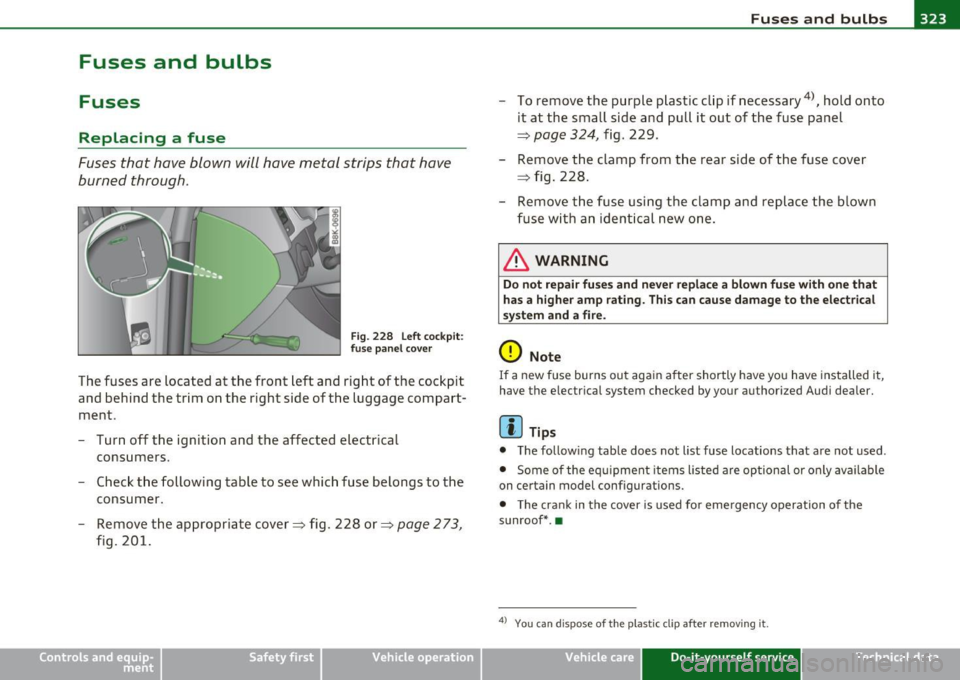
Fig. 228 Left cockpit:
fuse panel cover
The fuses are located at the front left and right of the cockpit
and behind the trim on the right side of the luggage compart
ment .
- Turn off the ignition and the affected electrical
consumers.
- Check the following table to see which fuse belongs to the
consumer.
- Remove the appropriate cover => fig. 228 or =>
page 2 73,
fig. 201.
Vehicle OP-eration
- To remove the purple plastic clip if necessary 4
), hold onto
it at the small side and pull it out of the fuse panel
~ page 324, fig. 229 .
- Remove the clamp from the rear side of the fuse cover
~ fig. 228.
- Remove the fuse using the clamp and replace the blown
fuse with an identical new one.
& WARNING
Do not repair fuses and never replace a blown fuse with one that
has a higher amp rating. This can cause damage to the electrical
system and a fire.
0 Note
If a new fuse burns out again after shortly have you have installed it,
have the electrical system checked by your authori zed Audi dealer.
[I] Tips
• The following table does not list fuse locations that are not used .
• Some of the equipment items listed are optional or only available
on certain model configurations.
• The crank in the cover is used for emergency operation of the
sunroof* .•
4
> You ca n dis p ose of the plastic cl ip after removi ng it.
Vehicle care Do-it-yourself service iTechnical data
Page 326 of 362
-Fuses and bulbs
~-;,_;__:_:_;..:..:.:....::~=---------------------------
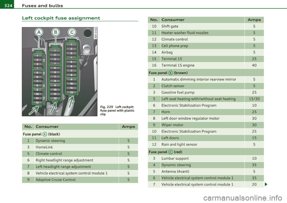
Left cockpit fuse assignment
No. C onsumer
Fu se p anel@ (bla ck )
1 Dynamic steering
3 Homelink
5 Climate control
6 Right headlight range adjustment
7 Left headlight range adjustment
F ig. 229 Left cockpit:
f use panel w ith p lastic
clip
Amps
5
5
5
8 Vehicle electrical system control module 1
5
5
5
5 9 Adaptive Cruise Control No. Con
sumer Amps
10 Shift gate 5
11 Heater washer fluid nozzles 5
12 Climate control 5
13 Cell phone prep 5
14 A irbag 5
15 Terminal 15 25
16 Terminal 15 engine
40
Fuse panel ® (brow n)
1 Automatic dimming interior rearv
iew mirror
5
2 Clutch sensor 5
3 Gasoline fuel pump
25
5 Left
seat heating with/without seat heating
15/30
6 Elect ronic Stabilization Program 10
7 Horn
25
8 Left door w
indow regulator motor
30
9 Wiper motor 30
10 Electronic Stabilization Program 25
11 Left doors 15
12 Ra in and light sensor 5
Fuse p an el © (red )
3 Lumbar support 10
4 Dynamic steering 35
5 Antenna (Avant)
5
6 Vehicle electrical system control module 1 35
7 Vehicle electrical system control modu le 1 20
Page 327 of 362
Fuses and bulbs -----------------------=---==-=-=--=.:..:..:::...:....:.:..:....-EWII
No. Consumer Amps
8 Vehicle electrical system control module 1
30
--
9 sunroof 20
10 Vehicle electrical system control module 1 30
11 sunroof shade (Avant)
20
12 Convenience electronics 5
•
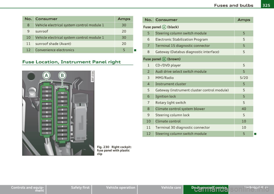
Fuse Location, Instrument Panel right
Fig. 230 Right cockpit:
f use panel with plastic
clip
Vehicle OP-eration
No. Consumer Amps
Fuse panel @ (black)
5 Steering column switch module
5
6 Electronic Stabilization Program
5
7 Terminal 15 diagnostic connector 5
8 Gateway (Databus diagnostic interface)
5
Fuse panel @ (brown)
1 CD-/DVD player
5
2 Audi drive select switch module 5
3 MMI/Radio 5/20
4 Instrument cluster 5
5 Gateway (instrument cluster control module)
5
6 Ignition lock 5
7 Rotary light switch 5
8 Climate control system blower 40
9 Steering column lock
5
10 Climate control 10
11 Terminal 30 d
iagnostic connector
10
12 Steering column switch module 5
•
Vehicle care Do-it-yourself service iTechnical data
Page 328 of 362
m...__F_ u_ s_e _ s_ a_n_d _b_u _ l_ b_s _______________________________________________ _
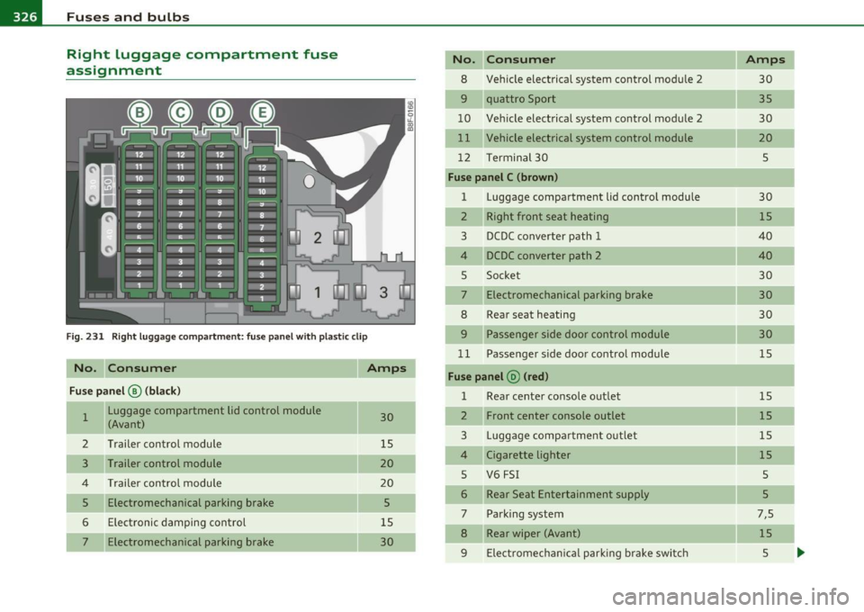
Right luggage compartment fuse
assignment
Fi g. 23 1 Ri ght luggage co mp artment : fu se pa nel with pl astic clip
No. Consumer Amps
Fuse panel @ (black)
1 Luggage compartment lid control module 30 (Avant)
2 Trai ler control module 15
3 Trailer control module 20
4 T rai ler control module 20
5 Electromechanical parking brake 5
6 Electronic damping control 15
Electromechanical parking b ra ke 30
No . Consumer
8 Ve hicle electrical system control mod ule 2
9 quattr o Sport
10 Veh icle elect rical system control modu le 2
11
Vehicle electrical system control module
12 T ermin al 30
Fuse panel C (brown )
1 Luggage compartment lid contro l modu le
2 R ight front seat heating
3 D CDC converter path 1
4 DCDC converter path 2
5 Soc ket
7 Electromechanical parking brake
8 Rear seat heating
9 Passenger side door control module
1 1 Passe nger s ide door control module
Fuse panel @ (red )
1 Rear center console o utlet
2 Front center console outlet
3 L ugg age compa rtme nt o utlet
4 Cigaret te lighter
5 V6 FSI
6 Rear Seat Enter tainmen t supply
7 Pa rking system
8 Rear wiper (Avant)
9 Elect romec ha ni ca l p arkin g br ake switc h
Amps
30
35
30
20
5
30
1 5
40
40
30
30
30
30
15
15
15
15
15
5
5
7,S
15
5
Page 329 of 362
_______________________________________________ F_u _s_ e_ s_ a_ n_ d_ b_u _ l_ b _ s __ lR
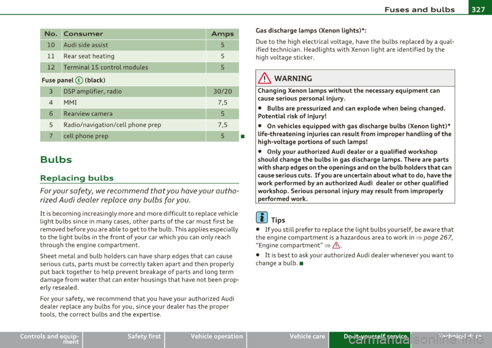
No. I I Consumer
1 0 A udi side assis t
1 1 Rea r seat he ating
1 2 T ermin al 15 control mod ules
Fuse panel © (black)
3 D 5P amplifi er, rad io
4 MMI
5
Rea rvi ew c amer a
Rad io/nav igatio n/cell phon e prep
cell phone prep
Bulbs
Replacing bulbs
Amps
5
5
5
30/ 20
7,5
5
7,5
5 •
For your sa fety, we recommend tha t you have your autho
ri zed A udi de aler repl ace any bulbs for y ou.
It is becoming increas ingly more and more difficu lt to replace veh icle
ligh t bulbs since in many cases, other parts o f the car m ust first be
removed before you are able to get to the bu lb. This app lies espec ia lly
t o the ligh t bulbs in the fron t of your car which you can on ly reac h
t hroug h the engi ne compartment .
Sheet meta l and bu lb holders can have sharp edges that can ca use
serious cuts, parts must be co rrectly take n apart a nd the n properly
put back together to he lp prevent breakage of parts and long term
damage from w ate r that c an ente r housings tha t have no t been prop
er ly resea led.
F or your safety, we recommend that you have your authorized Audi
dealer replace any bu lbs for you, s ince your dealer has the p rope r
too ls, the cor rect bu lbs and the expertise.
Safety first Gas discharge lamps
(Xenon lights}*:
Due to the high electr ica l voltage, have the bulbs replaced by a qual
ified technicia n. Headl ights w it h Xe non lig ht are ident ified by t he
high voltage sticker.
& WARNING
Changing Xenon lamp s without the nece ssary equipment can
cause serious personal injury.
• Bulbs are pre ssurized and can explode when being changed.
Potential risk of injury!
• On vehicle s equipp ed with ga s discharge bulbs (Xenon light)*
life-threatening injuries can result from improper handling of the
high-voltage portions of such lamps!
• Only your authorized Audi dealer or a qualified workshop
s hould change the bulbs in gas discharge lamp s. There are parts
with sharp edges on the openings and on the bulb holders that can
c au se seriou s cuts. If you are uncertain about what to do , have the
work performed by an authoriz ed Audi dealer or other qualified
workshop. Seriou s person al injury may result from improperly
performed work.
(I] Tips
• If you st ill prefer to replace t he lig ht bulbs yourself, be aware that
the engine compartment is a hazardo us a rea to work in:::)
page 267 ,
" E ng ine compartme nt" :::) & .
• It is best to ask your a uthorized Au di dea ler w henever you wa nt to
change a b ulb. •
Vehicle care Do-it-yourself service Technical data
Page 330 of 362
lffll.___E_ m_ e_ r-' g=- e_n_ c=-y _ s_it _ u _ a_t_ i_ o _ n_ s ______________________________________________ _
Emergency situations
General
This chapter is intended for trained emergency crew s and working
pe rsonnel who have the necessary tool s and equipment to perform
the se operation s. •
Starting by pushing or towing
0 Note
Veh icles with an automatic transmission cannot be started by
pushing or towing .•
Starting with jumper cables
If necess ary, the engine can be started b y connectin g it to
t he bat tery of another vehicle.
If the e ng ine shou ld fa il to start because of a discharged or weak
battery, the batte ry can be connected to t he battery of
another
veh icle, us ing a pair of jump er cables to start t he eng ine .
Jumper cables
Use only jumper cables of suffic iently large cross section to carry the
sta rter cur rent s afely . Refer to the m an ufa ct ur er's specificat ions.
Use only j umpe r cab les with
insulated te rmi nal clamps wh ich are
distinct ly marked :
plu s(+) cable i n most cases colored red
minus (-) cable i n most cases colored black .
& WARNING
Batterie s contain el ectricity, acid, and gas . Any of the se can cause
very serious or fatal injury. Follow the inst ructions below for safe
handling of your vehicle 's battery.
• Always shield your eyes and avoid leaning over the battery
whenev er po ssible .
• A discharged battery can freeze at temperatures just below
32 °F (0 °C ). Before connecting a jumper cable, you must thaw the
frozen battery completely, otherwise it could explode.
• Do not allow battery acid to contact eyes or sk in . Flush any
contacted area with water immedi ately .
• Improper use of a booste r battery to start a vehicle may cause
an explosion .
• Vehicle batteries generate e xplosive gases. Keep sparks, flame
and lighted cigarettes away from batterie s.
• Do not try to jump start any vehicle with a low acid level in the
battery.
• The voltage of the booster battery must also have a 12-Volt
rating. The capacity (Ah) of the booster battery should not be
lower than that of the discharged battery . Use of batteries of
different voltage or substantially different "Ah " rating may cau se
an e xplosion and personal injury.
• Never charge a frozen battery . Gas trapped in the ice may cause
an explosion.
• Never charge or use a battery that has been frozen. The battery
case may have be weakened .
• Use of batteries of different voltage or substantially different
capacity (Ah) rating may cause an explosion and injury . The
capacity (Ah) of the booster battery should not be lower than that
of the discharged battery. .,_