CD changer AUDI A5 COUPE 2012 Owners Manual
[x] Cancel search | Manufacturer: AUDI, Model Year: 2012, Model line: A5 COUPE, Model: AUDI A5 COUPE 2012Pages: 316, PDF Size: 78.59 MB
Page 11 of 316

CD
@
®
©
®
®
(j)
Door handle
Power locking sw it ch
Memory buttons (dr iver's seat)
Button for side ass ist .. ... .. .
A ' l 1 r out ets .... ..... ... .. .. .
L ight switch
Control lever for :
- T urn signal and high beam . .
® Multi-function steering wheel
with:
- Horn
- Driver's airbag ..... .. .. .. .
- Operating buttons for the au-
dio system
- Rocker switches for tiptronic
operation ........... .... .
® ISETI button ............... .
@ Instrument cluster .... ... .. .
@ Reset button for trip odometer
@ Sw itches for:
- Windshield wiper/washer .. .
- Trip computer ....... ... .. .
@ Ignition lock . .......... ... .
~ Adjustable steer ing column
@ Control lever for :
- Cruise control ............ .
- Adaptive cruise control .... .
@ Instrument lighting .... .. .. .
@ Release lever for the engine
hood
.. .. ................. .
@ Data Link Connector for On
Board Diagnostics (OBD II) . .. .
@ Switch for unlocking the trunk
lid
. . .. .. .. .. ........... .. .
@ Adjuster control for outside m ir-
r ors
@ Power window switches
@ MMI Display
@ D epending on opt io n s:
- Radio system
- CD changer
@ Emergency flasher
@ Glove compartment ( lockable) .
@ Front passenger's airbag .. .. . 43
65
116
89
49
52
166
131 11
1 0
12
55
22
92
92
99
102 5 1
237 26
44
57
46
52
77
166
In strument s and control s 9
@ Depending on options, switches
for :
- Aud i drive select ... .. ... .. . 124
- Electron ic Stabili zation Pro-
gram
- Rear w indow sun shade .....
@ Deluxe automat ic cl imate con- 204
54
t
ro l .... .. .. .. ............ .
@) Depending on options, selector
lever or shift lever for
83
- Manual transmission ...... . 126
- Automatic transmission . . . . . 126
@ Ashtray with cigarette lighter 75 , 76
@ Depend ing on options:
- MMI control console or
- Aud i drive select . . . . . . . . . . . 124
- Electron ic Stabili zation Pro-
gram bu tton . . . . . . . . . . . . . . 204
- Power switch for rear window
sun shade . . . . . . . . . . . . . . . .
54
@ I S TAR T ENG IN E ST OPI button 94
@ Electromechanical parking
brake .. . , ... , .. . , ... , . . . . . 96
(D Tips
- Some of the equipment or features
shown in the genera l ill ustration may be
standard equipment on your vehicle or
may be opt ional equ ipment depending
on your model. Always ask your author
ized Aud i dealer if you have a quest ion
about your vehicle .
- Operat ion of the Multi Med ia Interface
(MMI) is described in a separate manual.
Page 21 of 316

Driver information
display
Introduction
General notes
The driver informa tion display inside the in
strument cluster provides you, the driver,
with much useful information.
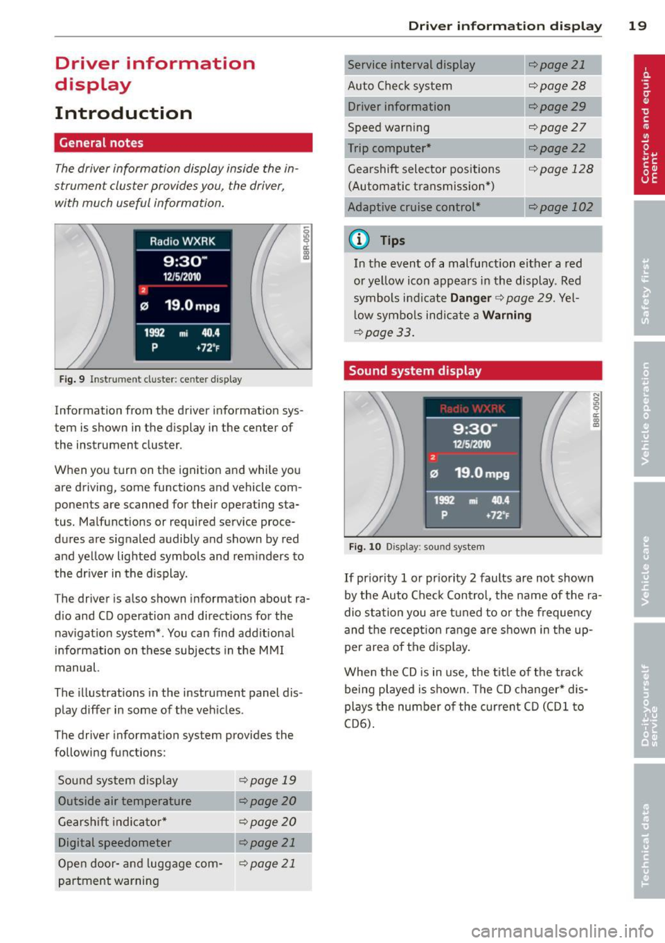
Fig. 9 Instr ument cluster: center d isplay
Information from the driver information sys
tem is shown in the display in the center of
the instrument cluster.
When you turn on the ignition and while you
are driving, some functions and vehicle com
ponents are scanned for their operating sta
tus. Malfunctions or required service proce
dures are signaled audibly and shown by red
and yellow lighted symbols and rem inders to
the dr iver in the display.
The driver is also shown information about ra
d io and CD operation and directions for the
nav igation system*. You can find add itional
i n formation on these subjects in the M MI
manual.
The illustrations in the instrument panel dis
play differ in some of the vehicles .
The driver information system provides the
following functions:
Sou nd system disp lay
¢page 19
Outside air temperature ¢ page 20
Gearshift indica tor * ¢ page 20
Digital speedometer ¢ page 21
Open door -and luggage com-¢page 21
partment warning
Driver inform ation di spl ay 19
Service interval display
Auto Chec k sys tem
Driver information
Speed warn ing
Trip computer*
Gearshift selector positions (Automatic transmission *)
Adaptive c ruise control*
a) Tips
¢page 21
¢page28
¢page29
¢page27
¢page22
cf) page 12 8
c::.page 102
In the event of a malfunction either a red
or yellow icon app ears in the display. Red
symbols indicate
Danger ¢ page 29. Yel
l ow symbo ls indicate a
Warning
¢page 33.
Sound system display
Fig. 10 Display: sound system
If priority 1 or pr iority 2 faults are not shown
by the Auto Check Contro l, the name of the ra
dio station you are t uned to o r the frequency
and the recept ion ran ge are shown in the up
per area of the d isplay .
When the CD is in use, the tit le of the track
being played is shown. The CD changer* dis
plays the number o f the cur rent C D (CDl to
CD6) .