buttons AUDI A5 COUPE 2018 Owners Manual
[x] Cancel search | Manufacturer: AUDI, Model Year: 2018, Model line: A5 COUPE, Model: AUDI A5 COUPE 2018Pages: 409, PDF Size: 67.63 MB
Page 11 of 409
<( a, .... N ,....
N .... 0 \0
3 a,
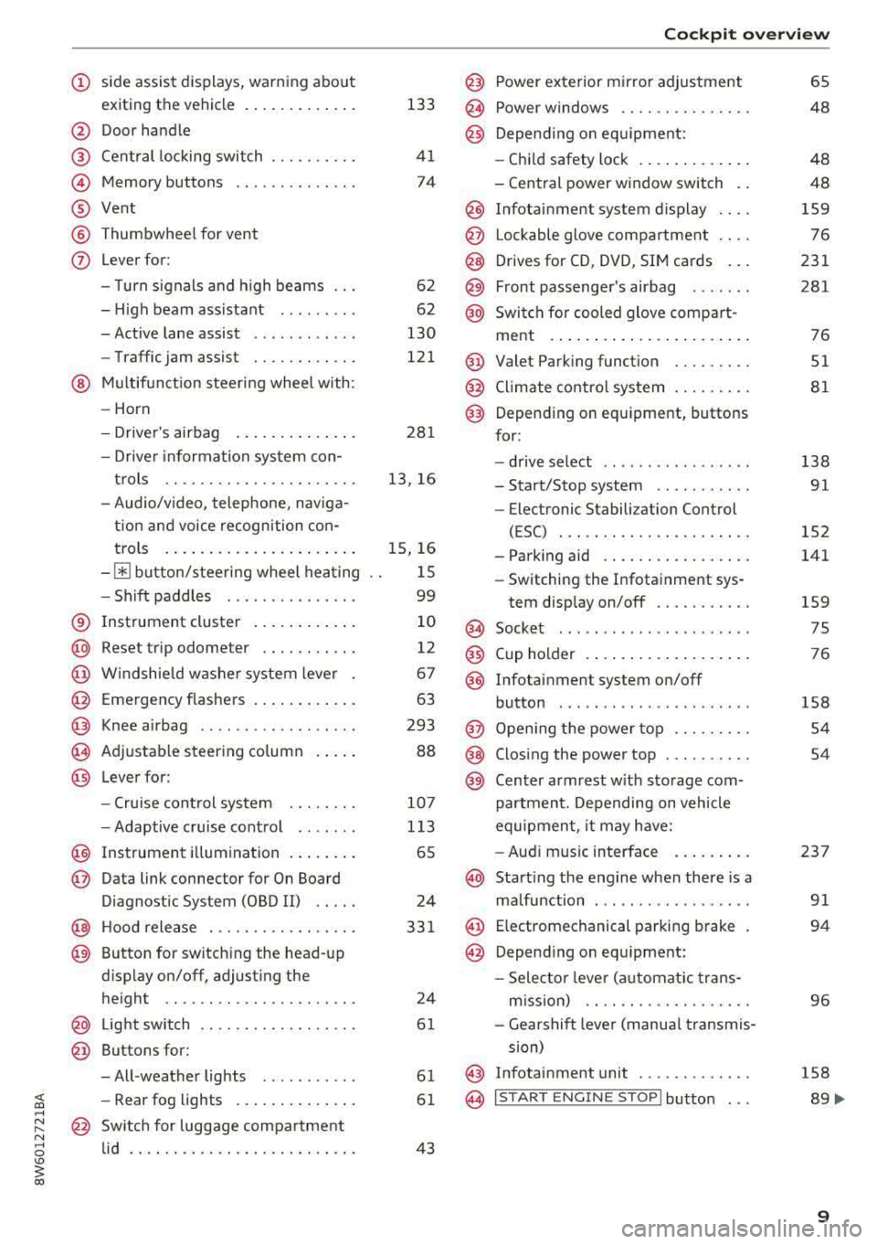
(!) side assist displays, warning abo ut
exiting the vehicle ..... ... .. .. .
@ Door handle
@ Cent ral locking switch ....... .. .
@ Memory buttons ........... .. .
® Vent
® Thumbwhee l for vent
(J) Lever for:
- T urn signals and h igh beams
- High beam assistant ........ .
- Active lane assist .. ..... ... . .
- Traffic jam assist ....... .. .. .
@ Mul tifunction steer ing wheel with:
- Horn
- Driver's airbag . ..... ... .. .. .
- Drive r information system con -
t rols .. .. ............. .. .. .
- Audio/v ideo, telephone, nav iga
t ion and voice recognition con-
trols . ... .... .. .... ... .. .. .
- ~ button/stee ring wheel heating
- Sh ift paddles .............. .
® Instrument cluster .... ... .. .. .
@
@
@
@
~
@
Reset trip odometer ........ .. .
W indshie ld washer system lever
Emergency flashers .... ... .. .. .
Knee a irbag ........ ..... ... . .
Adjustable steer ing column
Lever for:
- Cruise cont rol system ..... .. .
- Adaptive cruise cont rol .. ... . .
@ Instrument i llum ination ... .. .. .
@ Data link connector for On Board
Diagnostic System (OBD II) .. .. .
@ H ood release . ........... .. .. .
@ Button for switching the head-up
d isplay on/off, adjust ing the
height .. .. ............... .. .
@ Lig ht switch ............... .. .
@ Buttons for :
- All -weather lights .......... .
- Rear fog lights ........... .. .
@ Sw itch for luggage compartment
lid .. .. .. .. ............. .. .. .
133
41
74
6 2
62
130
121
281
13, 16
15, 16
1 5
99
10
12
67
63
293
88
107
1 13
65
24
33 1
24
61
61
61
43
Coc kpit o ve rv iew
@ Power exterior m irror adjustment
@ Power windows .............. .
@ Depend ing o n eq uipment:
- Chi ld safety lock . .. .. ..... .. .
- Central power w indow switch . .
@ Infotainment system display ... .
@ Lockable glove compa rtment ... .
@ Drives for CD, DVD, SIM cards .. .
@ Front passenge r's airbag ..... . .
@ Swi tch for cooled glove compa rt-
ment . ... .. .. ... .. .. ..... .. .
@ Valet Parking funct ion ........ .
@ Climate cont ro l system ........ .
@ Depending o n equipment, buttons
for :
- drive se lect .. .. .... .. ... .. . .
- Start/Stop system .......... .
- Electronic Stabili zation Control
(ESC) . .. .. .. .. .... . ..... .. .
- Parking aid .. .............. .
- Switching the I nfotainment sys-
tem disp lay on/off .......... .
(§) Socket ....... .. ............ .
@ Cup holder . .. ... .... . ..... .. .
@ Infotai nment system on/off
button ....... .. ............ .
@ Open ing t he power top ........ .
@ Closing the power top ......... .
@) Center armrest w it h sto rage com-
partmen t. D epending on vehicle
equipmen t, it may have:
- Audi m usic interface . ..... .. .
@ Start ing the eng ine when there is a
ma lfunction ... .. ... ....... .. .
@ E lectromechanical parking b rake
@ Depend ing o n equ ipment:
- Selector leve r (a utomat ic t ra ns-
m iss ion) .. . ... ............ .
- Gea rshif t leve r (manua l transmis
sion)
@ Infotainment unit ............ .
@ I START ENGINE STOP ! button . . .
65
48
48
48
159
76
231
281
76
51
81
138 91
152
141
159 75
76
158
54
54
237 91
94
96
158
89 ....
9
Page 15 of 409
Malfunction indicator
If there is a malfunction in the instrument clus
ter,
DEF wi ll appear in the trip odometer display.
Have the malfunction corrected as soon as possi
b le.
@ Tips
The units of measurement can be set in the
I nfotainment system
Q page 251.
Multifunction steering
wheel plus
Operating
Applies to: vehicles with multifunction steering wheel plus
You can use the multifunction steering wheel
plus to operate the driver information system
and the
MMI functions, adjust the volume and
switch the voice recognition system on and off.
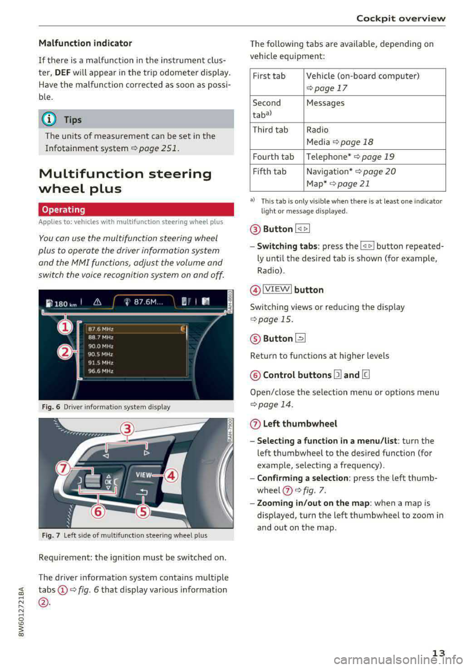
Fig. 6 Driver informat ion system d isplay
Fig. 7 left s ide of multifunc tion stee ring wheel p lus
Requirement: the ign ition must be switched on.
The driver information system contains multiple
~ tabs©¢ fig. 6 that display various information
~ @.
N ..... 0
'° ~ co
Cockpit overview
The following tabs are available, depending on
vehicle equipment:
First tab Vehicle (on-board computer)
Q page 17
Second Messages
tabal
Third tab Radio
Media
¢ page 18
Fourth tab Telephone* ¢ page 19
Fift h tab Navigation* ¢ page
20
Map* ¢page21
a) Thi s ta b is on ly vis ib le when t here is at leas t one indicato r
li ght o r m essag e disp layed .
@ Button I <1 1> I
-Switching tabs: press the ~ button repeated
ly until the desired tab is shown (for example ,
Radio) .
@IVIEWI button
Switching views or reducing the display
Q page 15.
@ Button [2l
Return to functions at higher levels
@ Control buttons 12) and [g
Open/close the selection menu or options menu
Qpage 14.
(z) Left thumbwheel
- Selecting a function in a menu/list:
turn the
left thumbwheel to the desired function (for
example, selecting a frequency) .
-Confirming a selection: press the left thumb
wheel
(J) ¢ fig . 7.
- Zooming in/out on the map: when a map is
displayed, turn the left thumbwheel to zoom in
and out on the map.
13
Page 16 of 409
Cockpit overview
Control buttons
Applies to: vehicles w ith mu ltifunct ion steering wheel p lus
I rM
' t M' ...
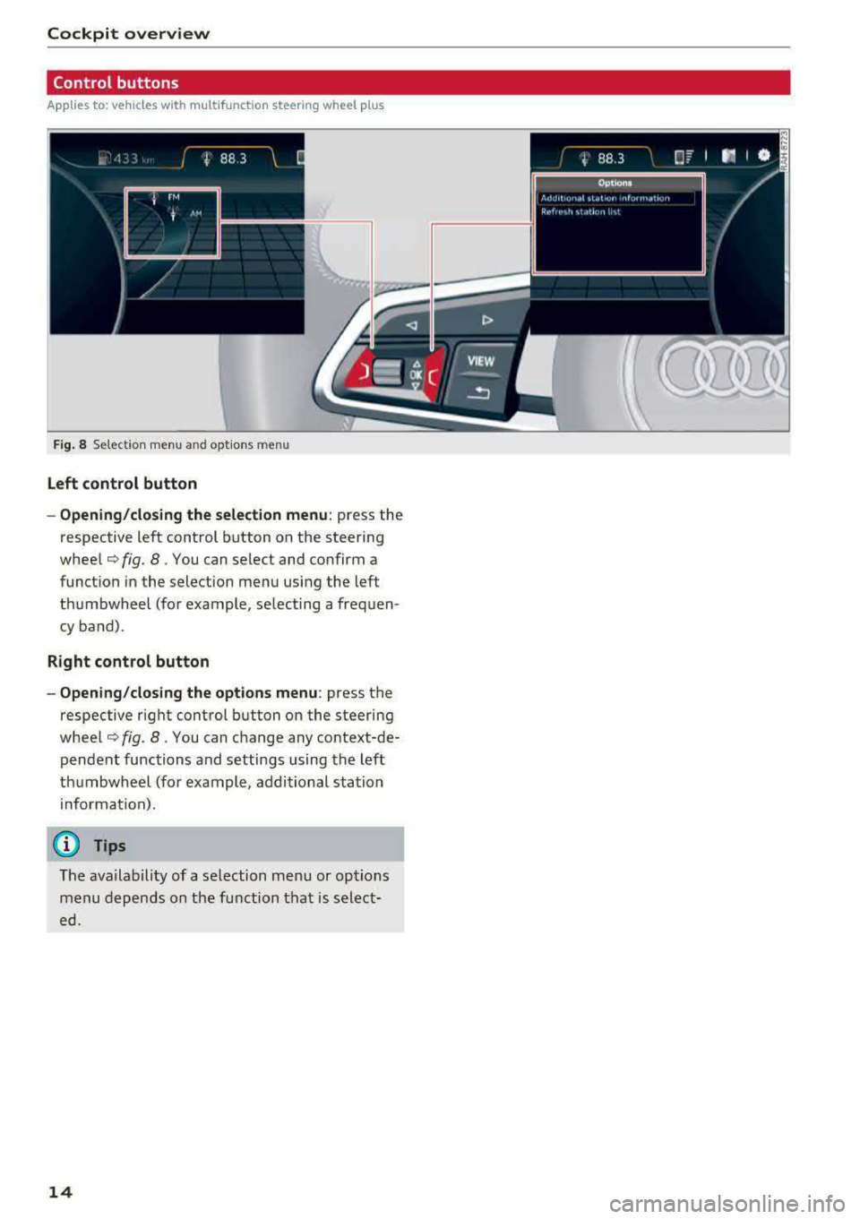
F ig . 8 Select ion menu an d opt io ns m en u
Left control button
- Opening/closing the selection menu :
press the
respective left control button on the steering
wheel¢ fig. 8. You can select and confirm a
function in the selection menu using the left
thumbwheel (for example , selecting a frequen
cy band).
Right control button
- Opening/closing the options menu :
press the
respective right control button on the steering
wheel¢ fig. 8. You can change any context-de
pendent functions and settings using the left
thumbwheel (for example, additional station
in format ion).
(D Tips
The ava ilability of a se lection menu or options
menu depends on the function that is select
ed.
14
Page 41 of 409
in the same frequency range (s uch as a ce ll
phone or radio equipment) . A lways check if
your vehicle is locked!
- For an explanation on conformity with t he
FCC regulations in the United States and the
Ind ustry Canada regu lations, see
<::> page 392 .
Removing the mechanical key
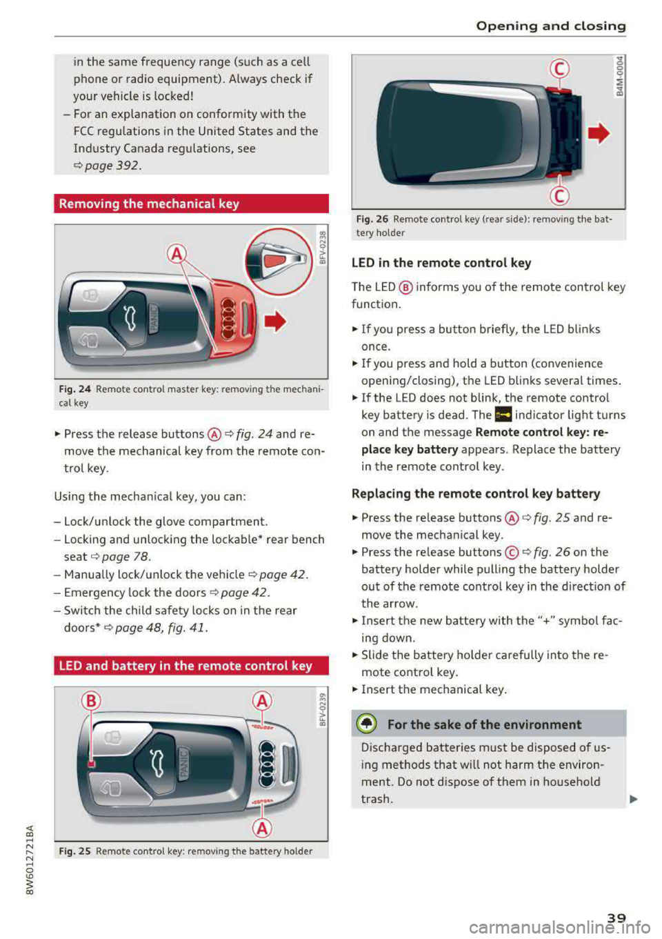
Fig. 24 Re mote control maste r key: remov ing t he mechani
ca l key
• Press the release buttons @¢ fig. 24 and re
move t he mechanical key from the remote co n
t ro l key .
Using the mecha nica l key, you can :
- Lock/un lock the glove compartment.
- Locking and unlock ing the lockable* rea r bench
seat <::>
page 78.
-Manua lly lock/ un lock the vehicle ¢ page 42.
- Emergency lock the doors ¢ page 4 2 .
- Swi tch the child safety locks on in t he rear
doo rs *
¢ page 48, fig. 41.
LED and battery in the remote control key
F ig. 25 Remote co ntro l key : rem ov ing the battery holder
Open ing and closing
F ig . 2 6 Re mote co ntrol key (rea r side) : re m ovi ng t he bat ·
te ry ho ld er
LED in the remote control key
" 0 0 0
i
~
T he L ED @ in forms you of the remote control key
funct ion .
• If you press a bu tto n briefly, the LE D blinks
once .
• If you press and hold a button (convenience
opening/closing), the LED b links severa l times .
• If the LED does not blink, the remote contro l
key battery is dead . The
1:1 ind icato r light turns
on and the message
Remote control key : re
place key battery
appears . Replace the battery
in the remote cont ro l key .
Replacing the remote control key battery
• Press the re lease buttons @¢ fig. 25 and re
move the mechanica l key .
• Press the re lease buttons ©¢ fig. 26 on the
battery holder while pulling the battery holder
ou t of the remote contro l key in the d irect io n of
t he arrow .
• Inse rt t he new b attery with the "+" sym bol fa c
ing down.
• Slide t he battery holde r car efully into the re
mote contro l key .
• Insert t he mechanical key .
® For the sake of the environment
Discha rged bat teries m ust be disposed o f us
in g methods that w ill not harm the env iron
ment. Do not d ispose o f them in ho useho ld
trash.
39
Page 53 of 409
Valet parking function
Applies to: vehicles wit h valet parking funct ion
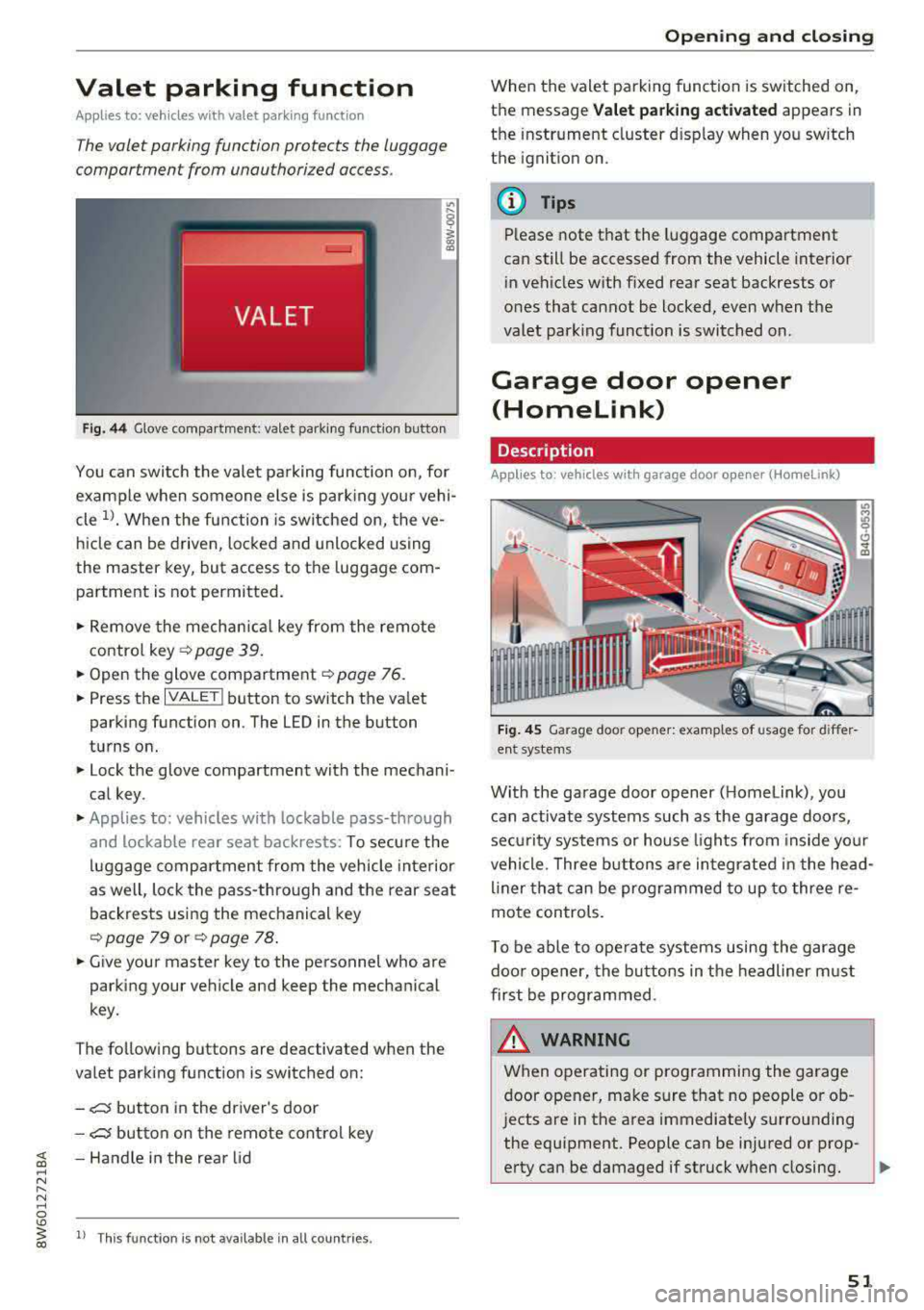
The valet parking function protects the luggage
comportment from unauthorized access.
Fig. 44 Glove compartment: valet parking function butto n
You can switch the valet parking function on, for
example when someone else is parking your vehi
cle
l)_ When the function is switched on, the ve
hicle can be driven, locked and unlocked using
the master key, but access to the luggage com
partment is not permitted .
.,. Remove the mechan ical key from the remote
contro l
key~ page 39 .
.,. Open the glove compartment ~ page 76 .
.,. Press the IVALET I button to switch the valet
parking function on . The LED in the button
turns on.
.,. Lock the glove compartment with the mechani
cal key .
.,. Applies to: vehicles with lockable pass-through
and lockable rear seat backrests: To secure the
luggage compartment from the vehicle interior
as well, lock the pass-through and the rear seat
backrests using the mechanical key
~ page 79 or ~ page 78 .
.,. Give your master key to the personnel who are
parking your vehicle and keep the mechanical
key.
The following buttons are deactivated when the
va let parking function is switched on:
-,c:;5 button in the driver's door
-,c:;5 button on the remote control key
~ -Handle in the rear lid ..... N
" N ..... 0
'° ~ ll Th is function is not available in all countr ies . co
Open ing and closing
When the valet parking function is switched on,
the message
Valet parking activated appears in
the instrument cluster disp lay when you sw itch
the ignition on.
@ Tips
Please note that the luggage compartment
can still be accessed from the vehicle interior
in vehicles with fixed rear seat backrests or
ones that cannot be locked, even when the
valet park ing funct ion is switched on.
Garage door opener
(Homelink)
Description
Applies to: vehicles with garage door opener (Home Link)
Fig. 45 Garage door opener: examples of usage for differ
ent system s
With the garage door opener ( Homelink), you
can activate systems such as the garage doors,
sec urity systems or house lights from inside your
vehicle. Three buttons are integrated in the head
liner that can be programmed to up to three re
mote controls.
T o be able to operate systems using the garage
door opener, the buttons in the headliner must
first be programmed .
_& WARNING ~
When operating or programming the garage
door opener, make sure that no people or ob
jects are in the area immediately s urrounding
the equipment. People can be injured or prop-
erty can be damaged if struck when closing.
Ill>
51
Page 54 of 409
Opening and clo sin g
@ Tips
- For security reasons, we recommend that
you clear the programmed buttons before selling the vehicle.
- For additional information about HomeLin k,
vis it www.homelink.com.
- Fo r an explanation on conformity with the
FCC regulations in the United States and the
Industry Canada regu lations, see
¢ page 392.
Operation
Appl ies to: ve hicles w ith ga ra g e doo r opener (Homeli nk)
Requirements: the button in the headliner must
be programmed
c::> page 52 and the vehicle
must be within range of the sys tem, such as the
garage door.
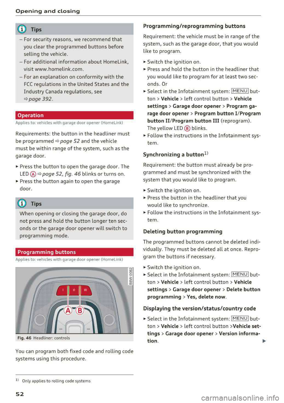
• Press the button to open the garage door . The
L E D @ c::> page 52, fig . 46 bli nks or turns on .
• Press the button again to open the garage
doo r.
@ Tips
When open ing o r closing the garage door, do
not p ress and hold the butto n longer ten sec
onds o r the ga rage door opene r will sw itch to
programmi ng mode.
Programming button s
App lies to: ve hicles w ith gara g e doo r opener (Homeli nk)
1 1 11~111
Fig . 4 6 Headliner: controls
N
"' 0
0
~ a,
You can p rogram bot h fixed code and roll ing code
sys tems using this procedure.
l) Only appl ie s to ro lli ng code system s
52
Programming /reprogramm ing buttons
Requireme nt: the vehicle m ust be in range of the
system, such as the garage door, that you would
li ke to program.
• Switch t he ignit io n on.
• Press and hold the b utton in the headliner that
you would like to program for at least two sec
onds. Or
• Select in the Infotainment system : IMENUj but
ton
> V ehicle > left control button > Vehicle
s e tting s> Garage door opener > Prog ram ga
rage door opener
> Prog ram bu tton I /P rogram
button II /Prog ram button
II I (reprogram) .
The ye llow LED @ blinks .
• Follow the in structions in the Info tainment sys-
tem.
Synchronizing a button1 )
Requireme nt: the button must already be pro·
grammed and must be synchronized with the
system that you wou ld like to program .
• Switch the ignition on .
• Press the button in the headliner that you
would like to synchronize.
• Follow the instructions in the Infotainment sys·
t ern.
Deleting button programming
The programmed buttons cannot be deleted indi·
vidually . They must be deleted all at once. Repro·
gram the buttons if necessary .
• Switch the ignit ion on.
• Select in the Infotainment system: IMENU j but·
ton
> Ve hicle > left control button > Vehicle
s etting s
> Garage door opener > Del ete button
programming
> Y es, del ete now .
Displa ying the version /status /country code
• Select in the Infotainment system: IMENUj but
ton
>V ehicle > left control button >V ehicle set·
ting s
> Garag e door opener > Version informa-
tion .
.,..
Page 63 of 409
Lights and Vision
Exterior Lighting
Switching the lights on and off
--- ----~------'~
i
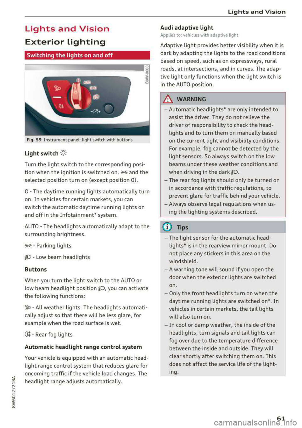
Fig . S9 Instrument panel: l ig ht sw itc h w ith buttons
Light switch ·'!;5- ·
Turn the light sw itch to the corresponding posi
tion when the ignition is switched on.
~oo: and the
selected pos ition turn on (except pos ition 0).
0 · The daytime r unning lights automat ica lly t urn
on. In veh icles for certain markets, you can
switch the automat ic daytime running lights on
and
off i n the Infotainment* system.
AUTO
-T he headlights automatically adapt to the
surrounding brightness.
~oo : -Parking lights
io -Low beam headlights
Buttons
When you turn the light switch to the AUTO or
l ow beam headlight pos it ion
io, you can activate
the following functions:
~ o -A ll weat her lights. The headlights automati
cally adjust so that there w ill be less glare, for
examp le when the road surface is wet.
0$ -Rear fog lights
Automatic headlight range control system
Your veh icle is equippe d with an autom atic head
l ight range contro l system that re duces glare fo r
oncoming traffic if the vehicle load c hanges. The
headlight range ad justs automatica lly.
Lights and V ision
Audi adaptive light
Appl ies to: vehicles wit h adaptive light
Ad aptive ligh t provides be tter visibili ty when i t is
dark by adapting the ligh ts to the road condi tions
based on speed, such as on e xpressways, rura l
roads, at intersections, and in c urves. The adap
t ive light only functions when the light switch is
i n the AUTO position .
A WARNING
--Automatic headlights* are on ly intended to
assist the driver. They do no t relieve the
driver of responsibil ity to check the head
lights and to turn t hem on manu ally b ased
on t he cur ren t ligh t and v is ibility conditi on s.
F o r e xamp le, fog canno t be de tec ted by t he
light sensors. So always swit ch o n the low
beams under these weather co nditions and
when dr iv ing in the dark
io .
- The rear fog lights s hou ld only be turned on
in acco rdance w ith traffic regulation s, to
prevent glare for traffic behind your vehicle.
- Always observe le g al regulations when
us
ing the lighting systems desc ribed .
(D Tips
- The lig ht sen sor for the automat ic he ad
ligh ts* is in the rearview mir ror mount. Do
not p lace any st ickers in this area on the
windshield.
- A warning tone will sound if yo u ope n the
door whe n the e xte rior lights a re switched
on .
- Only t he front headlights turn on when t he
daytime running lights are sw itche d on* . In
vehicles in certain markets, the tail lights
w ill also turn on.
- In cool or damp weather, the inside of the
head lights, turn signa ls and tail lights can
fog over due to the temperature diffe rence
b etween the insi de and outside . They wi ll
clear shortly afte r swi tching them on . This
does n ot aff ect the service life of the light
mg.
61
Page 76 of 409
Sea ts and stor age
Rear head restraints
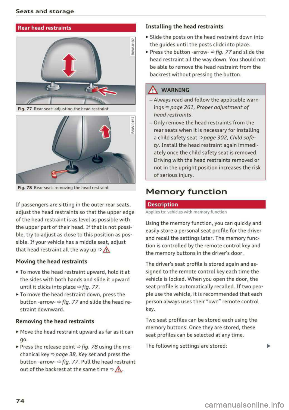
Fig. 77 Rear seat: adjust ing the head restraint
F ig. 78 Rear seat: remov ing the head rest rai nt
If passengers are s itting in the outer rear seats,
adjust the head restraints so that the upper edge
of the head restraint is as level as possible with
the upper part of their head . If that is not possi
ble, try to adjust as close to this position as pos
sible . If your vehicle has a middle seat, adjust
that head restra int all the way up
c::> .&.
Mov ing the he ad re st raints
• To move the head restraint upward, hold it at
the sides w ith both hands and slide it upward
unt il it clicks into place
c::> fig . 77.
• To move the head restraint down, press the
button -arrow-
c::> fig. 77 and slide the head re
straint downwa rd.
Remo ving the he ad rest raints
• Move the head restraint upward as far as it can
go.
• Press the release point c::> fig. 78 using the me
chanical
key~ page 38, Key set and press the
button -arrow-
c::> fig. 77. Pull the head rest raint
o ut of the backrest a t the same
time~ ,&..
74
Installing the head re straints
• Slide the posts on the head restraint down into
the guides until the posts click into place .
• Press the button -arrow-c::> fig. 77 and slide the
head restraint all the way down . You should not
be able to remove the head restraint from the
backrest without pressing the button.
A WARNING
-Always read and follow the applicable warn
ings~ page 261, Proper adjustment of
head restraints.
-Only remove the head restraints from the
rear seats when it is necessary for installing
a child safety seat
c::> page 302, Child safe
ty. Install the head restraint again immedi
ately once the ch ild safety seat is removed.
Driving w ith the head restra ints removed or
not in the upright position increases the risk
of serious injury .
Memory function
Description
Applies to: vehicles wit h memo ry funct ion
Using the memory function, you can quick ly and
easily store a persona l seat profile for t he driver
and recall the sett ings later. The memory func
tion is controlled by the remote control key and
the memory buttons in the driver's door.
The driver's seat prof ile is stored again and as
s igned to the remote control key each time the
vehicle is locked . When you open the door, the
seat profile is automatically recalled . If two peo
ple use the vehicle, it is recommended that each
person always uses their
"own" remote control
key.
Two seat profiles can be stored each using the
memory buttons. Once they are stored, these
seat profiles can be selected at any time.
The following sett ings a re stored:
Page 77 of 409
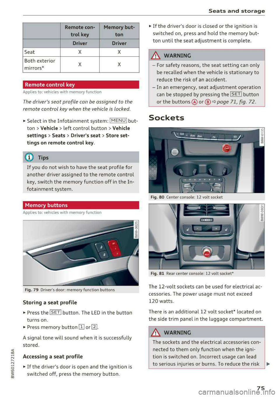
Remote con- Memory but-trol key ton
Driver Driver
Sea t X X
Both exterior
X X mirrors*
Remote control key
Applies to: vehicles with memory function
The driver's seat profile can be assigned to the
remote control key when the vehicle is locked .
.. Select in the Infotainment system: !MENUI but
ton
> Vehicle> left control button > Vehicle
settings
> Seats > Driver's seat > Store set
tings on remote control key.
@ Tips
If you do not wish to have the seat profile for
another driver assigned to the remote control
key, switch the memory function off in the In
fotainment system.
Memory buttons
Applies to: vehicles with memory function
Fig. 79 Driver's door: memory functio n buttons
Storing a seat profile
.. Press the ISET I button. The LED in the button
turns o n .
.. Press memory button IT] or~ -
A signal tone will sound when it is successfully
stored.
;:::: Accessing a seat profile ...... N
8 .. If the driver's door is open and the ignition is
'° ~ switched off, press the memory b utton. co
Seats and storage
.. If the driver's door is closed or the ignition is
switched on, press and hold the memory but
ton until the seat adjustment is complete .
_& WARNING
-For safety reasons, the seat setting can only
be recalled when the vehicle is stationary to
reduce the risk of an accident.
- In an emergency, seat adjustment operat ion
can be stopped by pressing the
ISE TI button
or the buttons @ or@
~ page 71, fig. 72.
Sockets
Fig. 80 Cen ter console : 12 vo lt socket
Fig. 81 Rear center console: 12 volt socket •
The 12-volt sockets can be used for electr ical ac
cessories . The power usage must not exceed
120 watts.
T here is an additiona l 12 volt socket* located on
the side tr im panel in the luggage compartment.
A WARNING
The sockets and the e lectrical accessories con
nected to them only function when the igni
tion is switched on. Incorrect usage can lead
to serious injuries or burns. To reduce the r isk
Ji--
75
Page 84 of 409

Warm and cold
3 zone deluxe automatic climate control
Operation
Fig. 94 3-zone de luxe automatic cl imate co ntrol : co ckp it co ntr ol s
Fig. 95 3-zo ne deluxe automatic cl imate co ntrol system : rear con trols
Press the knobs, buttons or rocker switches to
turn the functions on or off . When the funct ion is
sw itched on, the LED in the respective button or
knob turns
on¢ fig. 94. The rocker switches are
sensitive to touch. The driver and front passenger
settings can be adjusted separately.
You can adjust the settings for the rear of the ve
hicle using the controls in the rear
¢fig . 95.
On right-hand drive vehicles*, the functions of
the rocker switched ®
and® are switched .
OFF
climate control system
The OFF button switches the cl imate control sys
tem on or off. It also switches on when you press
82
another button or a knob. Airflow from outside is
blocked when the climate control system is
switched off .
A/C
Cooling mode
You can switch the cooling mode on or off using
the rocker switch ®· The air is not cooled and hu
midity is not removed when cooling mode is
switched off . This can cause fog on the windows.
Cooling mode switches off automatically when
the outside temperature is below zero.
A/Ceco
Cooling mode*
You can switch the eco cooling mode on or o ff us-
ing the rocker switch @. T he climate control
..,.