check engine AUDI A6 1995 C5 / 2.G ATQ Engine Motronic Injection System Servicing User Guide
[x] Cancel search | Manufacturer: AUDI, Model Year: 1995, Model line: A6, Model: AUDI A6 1995 C5 / 2.GPages: 78, PDF Size: 1 MB
Page 36 of 78
24-31
WARNING!
Fuel system is under pressure! Place a cloth
around the connection point before opening
system. Then release pressure by carefully
loosening connection point.
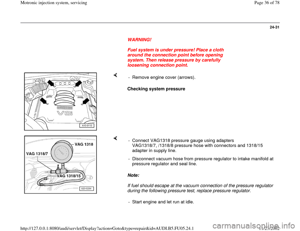
Checking system pressure - Remove engine cover (arrows).
Note:
If fuel should escape at the vacuum connection of the pressure regulator
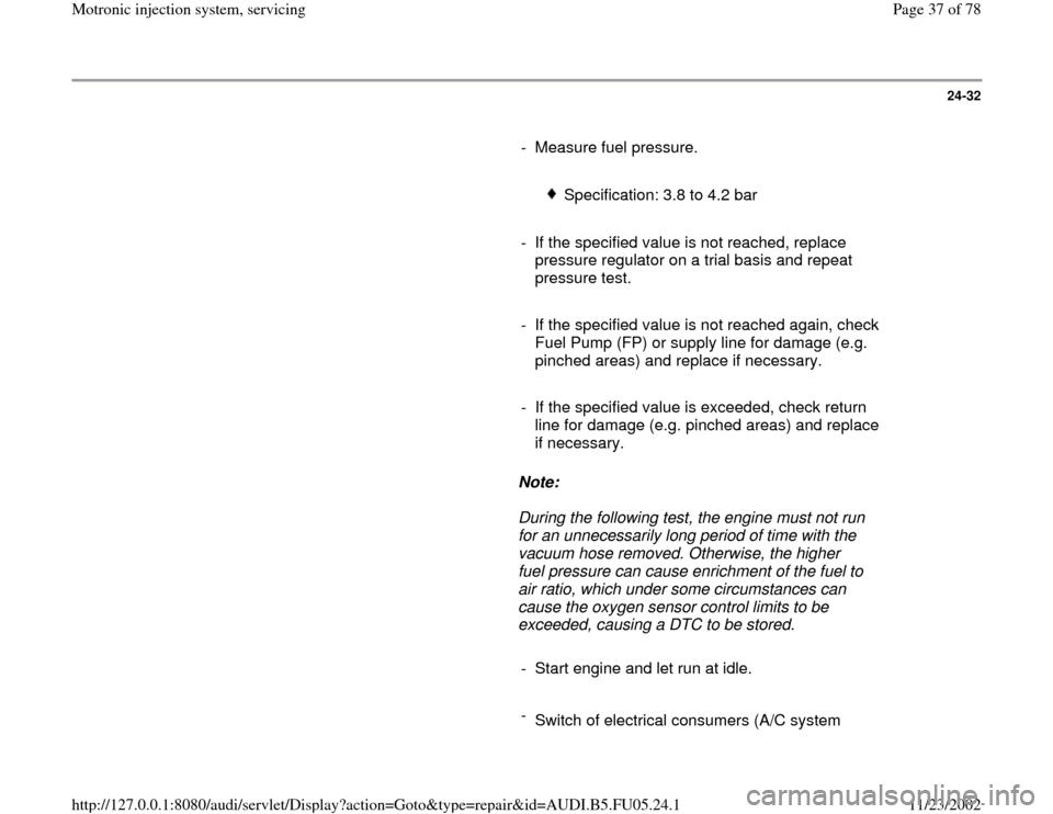
during the following pressure test, replace pressure regulator. - Connect VAG1318 pressure gauge using adapters
VAG1318/7, /1318/8 pressure hose with connectors and 1318/15
adapter in supply line.
- Disconnect vacuum hose from pressure regulator to intake manifold at
pressure regulator and seal line.
- Start engine and let run at idle.
Pa
ge 36 of 78 Motronic in
jection s
ystem, servicin
g
11/23/2002 htt
p://127.0.0.1:8080/audi/servlet/Dis
play?action=Goto&t
yp
e=re
pair&id=AUDI.B5.FU05.24.1
Page 37 of 78
24-32
- Measure fuel pressure.
Specification: 3.8 to 4.2 bar
- If the specified value is not reached, replace
pressure regulator on a trial basis and repeat
pressure test.
- If the specified value is not reached again, check
Fuel Pump (FP) or supply line for damage (e.g.
pinched areas) and replace if necessary.
- If the specified value is exceeded, check return
line for damage (e.g. pinched areas) and replace
if necessary.
Note:
During the following test, the engine must not run
for an unnecessarily long period of time with the
vacuum hose removed. Otherwise, the higher
fuel pressure can cause enrichment of the fuel to
air ratio, which under some circumstances can
cause the oxygen sensor control limits to be
exceeded, causing a DTC to be stored.
- Start engine and let run at idle.
-
Switch of electrical consumers (A/C system
Pa
ge 37 of 78 Motronic in
jection s
ystem, servicin
g
11/23/2002 htt
p://127.0.0.1:8080/audi/servlet/Dis
play?action=Goto&t
yp
e=re
pair&id=AUDI.B5.FU05.24.1
Page 39 of 78
24-33
- Fuel pressure must drop by approx. 0.5 bar
when connecting the vacuum hose.
If the pressure change does not occur, the
following tests must be performed:
Check vacuum hose for tears and
damage.
Check vacuum hose at intake manifold for
throughput by disconnecting from pressure
regulator and blowing into it.
- If no leaks can be detected and if the vacuum
hose has throughput, replace the pressure
regulator.
Checking residual pressure
- Residual pressure 10 minutes after switching
engine off (minimum pressure).
Specified value with a cold engine: approx.
2.2 bar
Specified value with the engine at operating
temperature: approx. 3.0 bar
Pa
ge 39 of 78 Motronic in
jection s
ystem, servicin
g
11/23/2002 htt
p://127.0.0.1:8080/audi/servlet/Dis
play?action=Goto&t
yp
e=re
pair&id=AUDI.B5.FU05.24.1
Page 41 of 78
24-34
- Start engine and let run at idle.
The following malfunction are possible if the pressure does not drop:
Repair Manual, Fuel Supply System, Repair Group 20; Fuel supply
-
Front Wheel Drive or fuel supply
- All Wheel Drive
Note:
Pressure gauge displays the pressure behind the stopcock "intake
manifold side" after the stopcock is closed (in direction of fuel injector, fuel
pressure regulator). If the pressure drops in front of the stopcock (in
direction of fuel tank), the device cannot detect it. For this reason, the
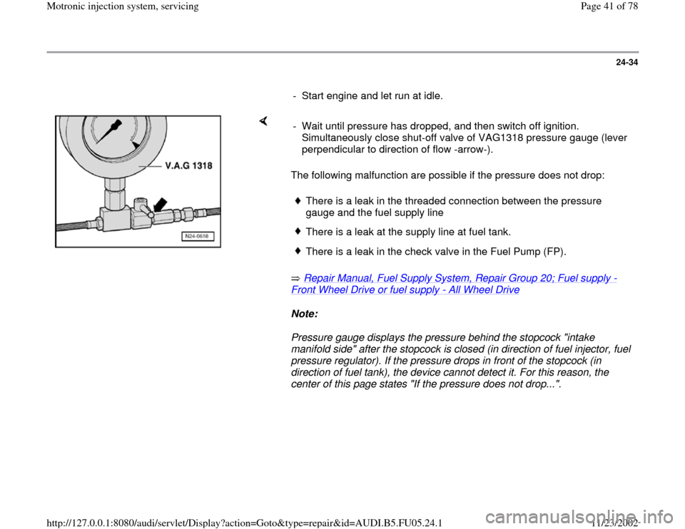
center of this page states "If the pressure does not drop...". - Wait until pressure has dropped, and then switch off ignition.
Simultaneously close shut-off valve of VAG1318 pressure gauge (lever
perpendicular to direction of flow -arrow-).
There is a leak in the threaded connection between the pressure
gauge and the fuel supply line There is a leak at the supply line at fuel tank.There is a leak in the check valve in the Fuel Pump (FP).
Pa
ge 41 of 78 Motronic in
jection s
ystem, servicin
g
11/23/2002 htt
p://127.0.0.1:8080/audi/servlet/Dis
play?action=Goto&t
yp
e=re
pair&id=AUDI.B5.FU05.24.1
Page 44 of 78
24-37
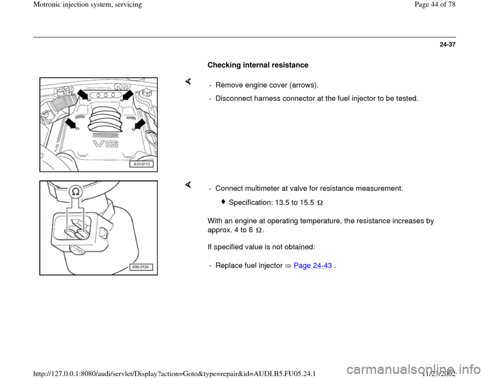
Checking internal resistance
- Remove engine cover (arrows).
- Disconnect harness connector at the fuel injector to be tested.
With an engine at operating temperature, the resistance increases by
approx. 4 to 6 .
If specified value is not obtained: - Connect multimeter at valve for resistance measurement.
Specification: 13.5 to 15.5
- Replace fuel injector Page 24
-43
.
Pa
ge 44 of 78 Motronic in
jection s
ystem, servicin
g
11/23/2002 htt
p://127.0.0.1:8080/audi/servlet/Dis
play?action=Goto&t
yp
e=re
pair&id=AUDI.B5.FU05.24.1
Page 45 of 78
24-38
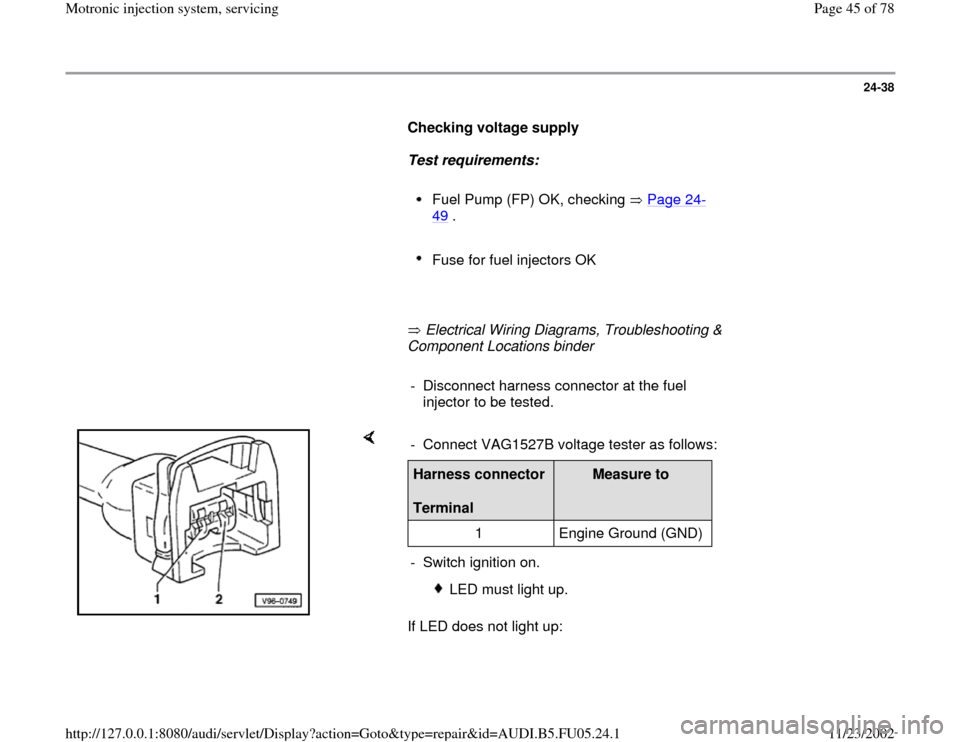
Checking voltage supply
Test requirements:
Fuel Pump (FP) OK, checking Page 24
-
49
.
Fuse for fuel injectors OK
Electrical Wiring Diagrams, Troubleshooting &
Component Locations binder
- Disconnect harness connector at the fuel
injector to be tested.
If LED does not light up: - Connect VAG1527B voltage tester as follows:Harness connector
Terminal
Measure to
1 Engine Ground (GND)
- Switch ignition on.
LED must light up.
Pa
ge 45 of 78 Motronic in
jection s
ystem, servicin
g
11/23/2002 htt
p://127.0.0.1:8080/audi/servlet/Dis
play?action=Goto&t
yp
e=re
pair&id=AUDI.B5.FU05.24.1
Page 47 of 78
24-39
- Repair open circuit if necessary.
If LED lights up:
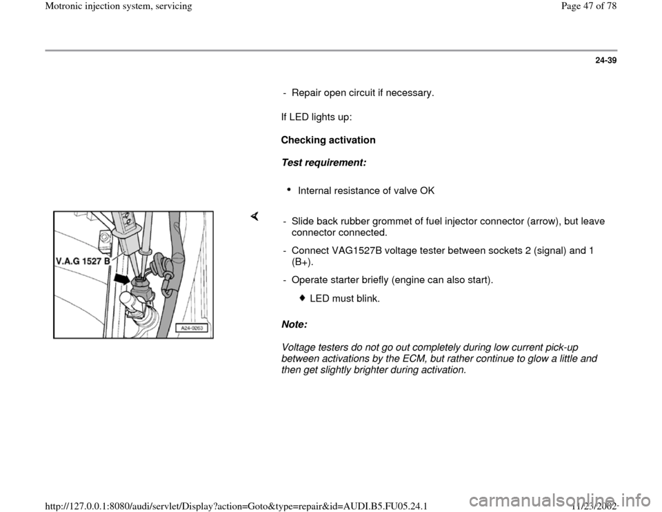
Checking activation
Test requirement:
Internal resistance of valve OK
Note:
Voltage testers do not go out completely during low current pick-up
between activations by the ECM, but rather continue to glow a little and
then get slightly brighter during activation. - Slide back rubber grommet of fuel injector connector (arrow), but leave
connector connected.
- Connect VAG1527B voltage tester between sockets 2 (signal) and 1
(B+).
- Operate starter briefly (engine can also start).
LED must blink.
Pa
ge 47 of 78 Motronic in
jection s
ystem, servicin
g
11/23/2002 htt
p://127.0.0.1:8080/audi/servlet/Dis
play?action=Goto&t
yp
e=re
pair&id=AUDI.B5.FU05.24.1
Page 48 of 78
24-40
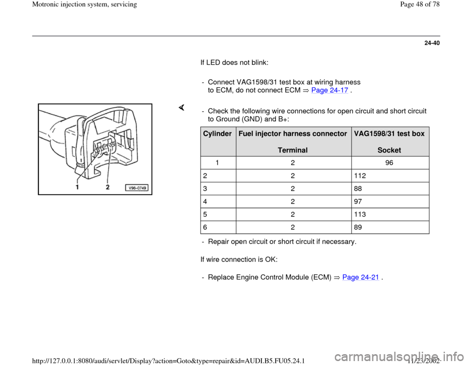
If LED does not blink:
- Connect VAG1598/31 test box at wiring harness
to ECM, do not connect ECM Page 24
-17
.
If wire connection is OK: - Check the following wire connections for open circuit and short circuit
to Ground (GND) and B+: Cylinder
Fuel injector harness connector
Terminal
VAG1598/31 test box
Socket
1 2 96
2 2 112
3 2 88
4 2 97
5 2 113
6 2 89
- Repair open circuit or short circuit if necessary.
- Replace Engine Control Module (ECM) Page 24
-21
.
Pa
ge 48 of 78 Motronic in
jection s
ystem, servicin
g
11/23/2002 htt
p://127.0.0.1:8080/audi/servlet/Dis
play?action=Goto&t
yp
e=re
pair&id=AUDI.B5.FU05.24.1
Page 49 of 78
24-41
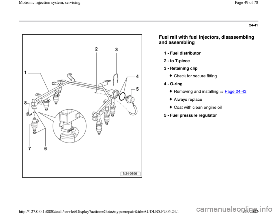
Fuel rail with fuel injectors, disassembling
and assembling
1 -
Fuel distributor
2 -
to T-piece
3 -
Retaining clip
Check for secure fitting
4 -
O-ring Removing and installing Page 24
-43
Always replaceCoat with clean engine oil
5 -
Fuel pressure regulator
Pa
ge 49 of 78 Motronic in
jection s
ystem, servicin
g
11/23/2002 htt
p://127.0.0.1:8080/audi/servlet/Dis
play?action=Goto&t
yp
e=re
pair&id=AUDI.B5.FU05.24.1
Page 52 of 78
24-44
- Disengage retaining clip and remove fuel
injector.
Note:
Fuel lines must be disconnected before replacing
fuel distributor.
Installation is reverse of removal, noting the
following:
Remove O-rings at all opened connections.
(Never remove plastic cap from valve head
to replace front O-ring - pry O-ring off over
plastic cap).
Lightly lubricate O-rings with clean engine
oil.
Make sure fuel injectors are in place and
seated correctly
Check clip for unobstructed fitting.
Place fuel rail with secured fuel injectors
onto intake manifold, and apply uniform
pressure to press it in.
Tightening torque
Pa
ge 52 of 78 Motronic in
jection s
ystem, servicin
g
11/23/2002 htt
p://127.0.0.1:8080/audi/servlet/Dis
play?action=Goto&t
yp
e=re
pair&id=AUDI.B5.FU05.24.1