sensor AUDI A6 1996 C5 / 2.G AEB Engine Motronic MFI And Ignition System
[x] Cancel search | Manufacturer: AUDI, Model Year: 1996, Model line: A6, Model: AUDI A6 1996 C5 / 2.GPages: 135, PDF Size: 0.71 MB
Page 51 of 135

24-37
- Compare display and specified values (display
fields 1 and 2):
Display fields
1 2 3 4
Display group 36: Heated Oxygen Sensor (HO2S) behind Three Way Catalytic Converter (TWC)
Display x.xxx V B1-S2 ON
B1-S2 OFF
Indicates Voltage supply to HO2S behind TWC HO2S behind TWC
ON/OFF
Range 0.000-1.000 V ---
Specified value 0.000-1.000 V
(can oscillate slightly) B1-S2 ON
If not as specified Page 24
-38
, Continuation
Pa
ge 51 of 135 Motronic Multi
port Fuel In
jection
(MFI
) and i
gnition s
ystem
11/19/2002 htt
p://127.0.0.1:8080/audi/servlet/Dis
play?action=Goto&t
yp
e=re
pair&id=AUDI.B5.FU02.24.1
Page 52 of 135

24-38
Continuation
If displayed values are NOT OK (not as
specified):
- Road test to condition oxygen sensor (eliminate
possible contamination) and repeat test.
If the values in display fields 1 and 2 are still
NOT OK:
- Check Oxygen Sensor (O2S) heater Page 24
-
43
.
- Briefly accelerate engine over 3000 RPM.
If the value in display field 1 remains constant:
page Page 24
-39
, Evaluation of display group
36.
Pa
ge 52 of 135 Motronic Multi
port Fuel In
jection
(MFI
) and i
gnition s
ystem
11/19/2002 htt
p://127.0.0.1:8080/audi/servlet/Dis
play?action=Goto&t
yp
e=re
pair&id=AUDI.B5.FU02.24.1
Page 53 of 135

24-39
Evaluation of display group 36 Display group:
36
Display field: 1
Possible causes
Corrective action
approx. 0.435
V
Open circuit in wiring -4- between oxygen sensor and ECM - Check basic voltage Page 24
-40
approx. 0.440
V
Open circuit in wiring -4- between oxygen sensor and ECM
approx. 1.085
V Short circuit to B+ in wiring -4- between oxygen sensor
and ECM - Check wiring for oxygen sensor
Page 24
-41
approx. 0.000
V
Short circuit to Ground in wiring -4- between oxygen
sensor and ECM
Pa
ge 53 of 135 Motronic Multi
port Fuel In
jection
(MFI
) and i
gnition s
ystem
11/19/2002 htt
p://127.0.0.1:8080/audi/servlet/Dis
play?action=Goto&t
yp
e=re
pair&id=AUDI.B5.FU02.24.1
Page 54 of 135

24-40
Checking HO2S reference voltage
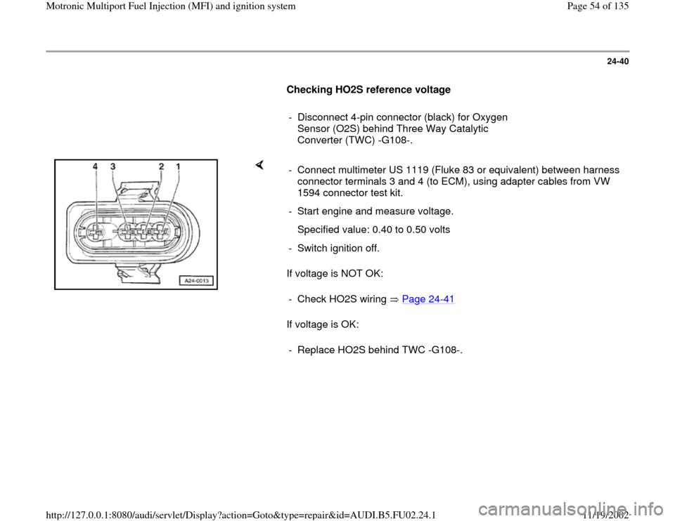
- Disconnect 4-pin connector (black) for Oxygen
Sensor (O2S) behind Three Way Catalytic
Converter (TWC) -G108-.
If voltage is NOT OK:
If voltage is OK: - Connect multimeter US 1119 (Fluke 83 or equivalent) between harness
connector terminals 3 and 4 (to ECM), using adapter cables from VW
1594 connector test kit.
- Start engine and measure voltage.
Specified value: 0.40 to 0.50 volts
- Switch ignition off.
- Check HO2S wiring Page 24
-41
- Replace HO2S behind TWC -G108-.
Pa
ge 54 of 135 Motronic Multi
port Fuel In
jection
(MFI
) and i
gnition s
ystem
11/19/2002 htt
p://127.0.0.1:8080/audi/servlet/Dis
play?action=Goto&t
yp
e=re
pair&id=AUDI.B5.FU02.24.1
Page 55 of 135

24-41
Checking HO2S wiring
- Connect VAG 1598/22 test box to ECM harness
connector Page 01
-56
.
- Disconnect 4-pin connector (black) for Heated
Oxygen Sensor (HO2S) behind Three Way
Catalytic Converter (TWC) -G108-.
- Check wiring for open circuit between ECM/test box and 4-pin HO2S
harness connector (to ECM).
Connector terminal 3 to ECM/test box socket 51
Connector terminal 4 to ECM/test box socket 52
Specified value: max. 1.5
- Check wiring for short circuits between terminals of 4-pin connector,
between connector, ECM/test box, and shielding for wiring harness.
Connector terminal 4 to ECM/test box socket 51
Connector terminal 3 to ECM/test box socket 2
Connector terminal 4 to ECM/test box socket 2
Specified value:
Pa
ge 55 of 135 Motronic Multi
port Fuel In
jection
(MFI
) and i
gnition s
ystem
11/19/2002 htt
p://127.0.0.1:8080/audi/servlet/Dis
play?action=Goto&t
yp
e=re
pair&id=AUDI.B5.FU02.24.1
Page 57 of 135

24-43
Oxygen Sensor (O2S) heater (behind
TWC), checking
Notes:
Harness connector for Oxygen Sensor (O2S)
heater: 4-pin, black
Component locations Page 24
-1
Required special tools and test equipment
VAG 1551 or VAG 1552 Scan Tool (ST) with
VAG 1551/3 adapter cable
VAG 1598/22 test box
Multimeter US 1119 (Fluke 83 or equivalent)
VW 1594 connector test kit
Wiring diagram
Test requirements
Fuse for Oxygen Sensor (O2S) heater OK
Pa
ge 57 of 135 Motronic Multi
port Fuel In
jection
(MFI
) and i
gnition s
ystem
11/19/2002 htt
p://127.0.0.1:8080/audi/servlet/Dis
play?action=Goto&t
yp
e=re
pair&id=AUDI.B5.FU02.24.1
Page 60 of 135

24-45
- Compare display and specified values (display
fields 3 and 4):
Display fields
1 2 3 4
Display group 41: Oxygen Sensor (O2S) heater, before and after Three Way Catalytic Converter (TWC)
Display
xx.x
Htg.bC.ON/Htg.bC.OFF
xx.x
Htg.aC.ON/Htg.aC.OFF
Indicates Resistance of Oxygen
Sensor (O2S) heater
before TWC O2S heater on
or
O2S heater off
(before TWC) Resistance of oxygen sensor
(O2S) heater
(after TWC) O2S heater on
or
O2S heater off
(after TWC)
Range --- ---
0.0-65.0
---
Specified
value --- ---
4.9-19.9
Htg.aC.ON
--- --- If not as specified Page
24
-46
, Continuation
---
If displayed values are OK (as specified):
-
Press button to advance program
sequence.
-
Press buttons -0- and -6- to select "End Output"
Pa
ge 60 of 135 Motronic Multi
port Fuel In
jection
(MFI
) and i
gnition s
ystem
11/19/2002 htt
p://127.0.0.1:8080/audi/servlet/Dis
play?action=Goto&t
yp
e=re
pair&id=AUDI.B5.FU02.24.1
Page 62 of 135

24-46
Continuation
- Disconnect 4-pin connector (black) for Oxygen
Sensor (O2S) 2 -G108- behind Three Way
Catalytic Converter (TWC).
If resistance is NOT OK:
If resistance is OK: - Connect multimeter US 1119 (Fluke 83 or equivalent) between HO2S
connector terminals 1 and 2, using VW 1594 connector test kit.
- Measure resistance.
Specified value: 0.00-19.9 - Replace Heated Oxygen Sensor (HO2S) behind TWC -G108-.
- Switch multimeter to 20 VDC measuring range.
Pa
ge 62 of 135 Motronic Multi
port Fuel In
jection
(MFI
) and i
gnition s
ystem
11/19/2002 htt
p://127.0.0.1:8080/audi/servlet/Dis
play?action=Goto&t
yp
e=re
pair&id=AUDI.B5.FU02.24.1
Page 67 of 135

24-51
Oxygen Sensor (O2S) aging, checking
Required special tools and test equipment
VAG 1551 or VAG 1552 Scan Tool (ST) with
VAG 1551/3 adapter cable
Test requirements
Engine Coolant Temperature (ECT) at least
85 C (185 F)
Pa
ge 67 of 135 Motronic Multi
port Fuel In
jection
(MFI
) and i
gnition s
ystem
11/19/2002 htt
p://127.0.0.1:8080/audi/servlet/Dis
play?action=Goto&t
yp
e=re
pair&id=AUDI.B5.FU02.24.1
Page 68 of 135

24-52
Function test
- Connect VAG 1551 or VAG 1552 scan tool and
press buttons -0- and -1- to insert "Engine
Electronics" address word 01 (with engine
running at idle) Page 01
-7 .
Rapid data transfer
HELP
Select function XX
Indicated on display
- Press buttons -0- and -4- to select "Basic Setting" function 04, and
press -Q- button to confirm input.
System in Basic Settin
g
HELP
Input displa
y group number XXX
Indicated on display
- Press buttons -0-, -3- and -4- to input display group number 34, and
press -Q- button to confirm input.
System in Basic Setting 34 1 2 3 4
Indicated on display (1-4 = display fields)
Note:
To be sure that the temperature is within the specified range, the specified
RPM has to be maintained for at least 1 minute. Observe status of oxygen
sensor control in display field 4. - Increase engine speed to 1800-2200 RPM and compare display with
specified values for oxygen sensor aging (display fields 1-4).
Pa
ge 68 of 135 Motronic Multi
port Fuel In
jection
(MFI
) and i
gnition s
ystem
11/19/2002 htt
p://127.0.0.1:8080/audi/servlet/Dis
play?action=Goto&t
yp
e=re
pair&id=AUDI.B5.FU02.24.1