fuel pressure AUDI A6 1997 C5 / 2.G ATW Engine Motronic Fuel Injection Syst
[x] Cancel search | Manufacturer: AUDI, Model Year: 1997, Model line: A6, Model: AUDI A6 1997 C5 / 2.GPages: 81, PDF Size: 1.03 MB
Page 3 of 81
24-2
It is possible that the control module will
recognize a malfunction and store a DTC during
some tests. After completing all tests and
repairs, DTC memory should therefore be
checked and erased if necessary. Readiness
code must be generated after DTC memory is
erased Page 01
-73
.
Always switch ignition off before cleaning
engine.
The battery should only be disconnected and
reconnected when the ignition is turned off,
since otherwise the Engine Control Module
(ECM) can be damaged.
WARNING!
Fuel system is under pressure! Before
opening system, place rags around the
connection point. Then release pressure by
carefully loosening connection.
Pa
ge 3 of 81 Motronic fuel in
jection s
ystem, servicin
g
11/21/2002 htt
p://127.0.0.1:8080/audi/servlet/Dis
play?action=Goto&t
yp
e=re
pair&id=AUDI.B5.FU06.24.1
Page 5 of 81
24-4
Technical data
Engine identification
ATW (1.8 L / 5V/ 110 kW-engine)
Idle speed
Engine speed cannot be adjusted, it is regulated by idle
stabilization
Front Wheel Drive
(FWD)
All Wheel Drive (AWD)
740 to 860 RPM
800 to 920 RPM
Engine speed (RPM) limitation
via fuel injector shut-off
about 6800 RPM
Fuel pressure at idle speed Vacuum hose
connected about 3.5 bar positive pressure
Vacuum hose
disconnected about 4.0 bar positive pressure
Residual pressure after 10 min. at least 2.5 bar positive pressure
Fuel injectors Injection stream Dual-hole nozzle / same for all
injectors
Injection quantity (30 s)
135 10 ml
Resistance
(room temperature)
12 to 13
Pa
ge 5 of 81 Motronic fuel in
jection s
ystem, servicin
g
11/21/2002 htt
p://127.0.0.1:8080/audi/servlet/Dis
play?action=Goto&t
yp
e=re
pair&id=AUDI.B5.FU06.24.1
Page 8 of 81
24-7
Repair Manual, 1.8 Liter 4
-Cyl. 5V Turbo Engine
Mechanical, Engine Code(s): AEB, ATW, Repair Group 26; Secondary Air Injection (AIR) system, checking
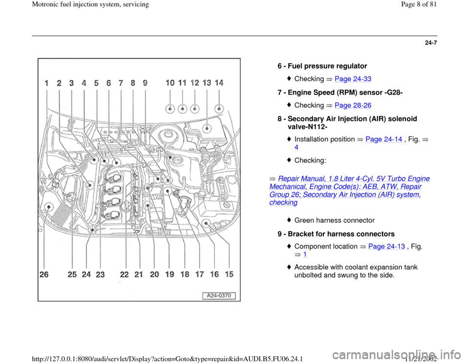
6 -
Fuel pressure regulator Checking Page 24
-33
7 -
Engine Speed (RPM) sensor -G28-
Checking Page 28
-26
8 -
Secondary Air Injection (AIR) solenoid
valve-N112-
Installation position Page 24
-14
, Fig.
4
Checking:Green harness connector
9 -
Bracket for harness connectors Component location Page 24
-13
, Fig.
1
Accessible with coolant expansion tank
unbolted and swung to the side.
Pa
ge 8 of 81 Motronic fuel in
jection s
ystem, servicin
g
11/21/2002 htt
p://127.0.0.1:8080/audi/servlet/Dis
play?action=Goto&t
yp
e=re
pair&id=AUDI.B5.FU06.24.1
Page 10 of 81
24-9
Repair Manual, 1.8 Liter 4
-Cyl. 5V Turbo Engine
Mechanical, Engine Code(s): AEB, ATW, Repair Group 26; Secondary Air Injection (AIR) system, checking
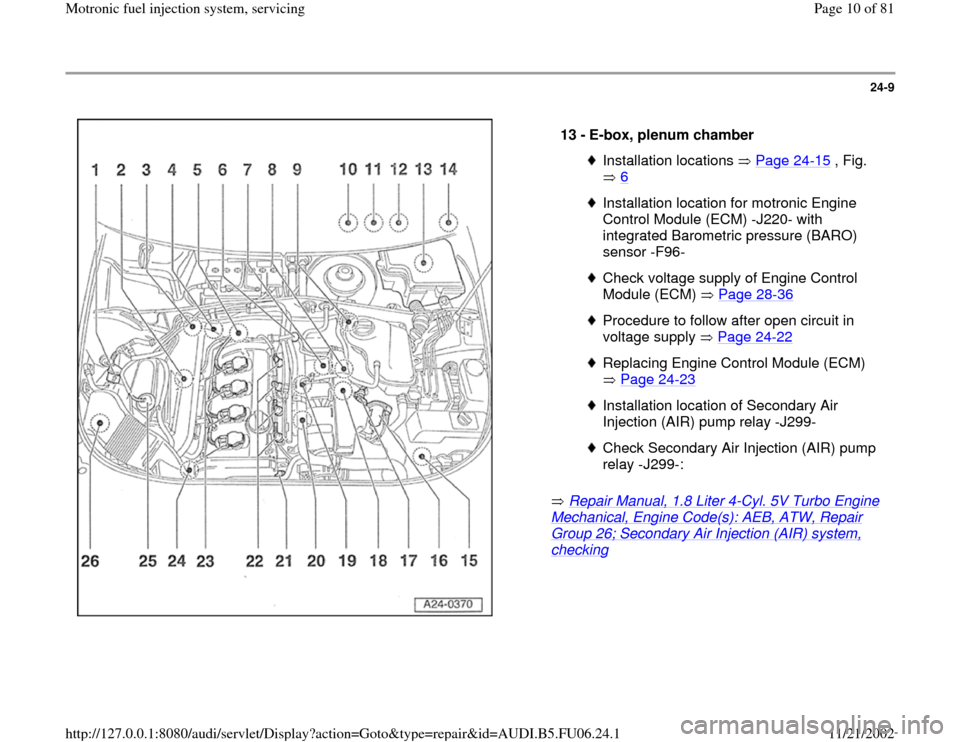
13 -
E-box, plenum chamber Installation locations Page 24
-15
, Fig.
6
Installation location for motronic Engine
Control Module (ECM) -J220- with
integrated Barometric pressure (BARO)
sensor -F96- Check voltage supply of Engine Control
Module (ECM) Page 28
-36
Procedure to follow after open circuit in
voltage supply Page 24
-22
Replacing Engine Control Module (ECM)
Page 24
-23
Installation location of Secondary Air
Injection (AIR) pump relay -J299- Check Secondary Air Injection (AIR) pump
relay -J299-:
Pa
ge 10 of 81 Motronic fuel in
jection s
ystem, servicin
g
11/21/2002 htt
p://127.0.0.1:8080/audi/servlet/Dis
play?action=Goto&t
yp
e=re
pair&id=AUDI.B5.FU06.24.1
Page 11 of 81
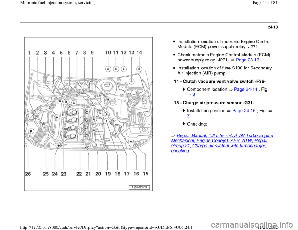
24-10
Repair Manual, 1.8 Liter 4
-Cyl. 5V Turbo Engine
Mechanical, Engine Code(s): AEB, ATW, Repair Group 21, Charge air system with turbocharger, checking
Installation location of motronic Engine Control
Module (ECM) power supply relay -J271-
Check motronic Engine Control Module (ECM)
power supply relay -J271- Page 28
-13
Installation location of fuse S130 for Secondary
Air Injection (AIR) pump
14 -
Clutch vacuum vent valve switch -F36-
Component location Page 24
-14
, Fig.
3
15 -
Charge air pressure sensor -G31-
Installation position Page 24
-16
, Fig.
7
Checking:
Pa
ge 11 of 81 Motronic fuel in
jection s
ystem, servicin
g
11/21/2002 htt
p://127.0.0.1:8080/audi/servlet/Dis
play?action=Goto&t
yp
e=re
pair&id=AUDI.B5.FU06.24.1
Page 17 of 81
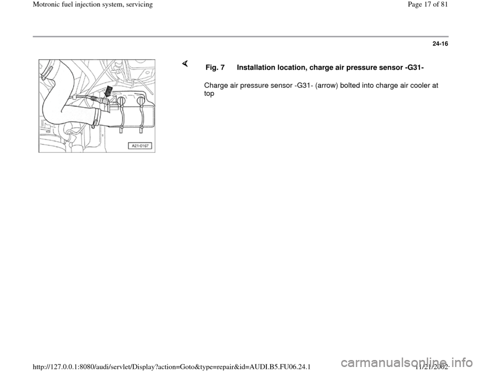
24-16
Charge air pressure sensor -G31- (arrow) bolted into charge air cooler at
top Fig. 7 Installation location, charge air pressure sensor -G31-
Pa
ge 17 of 81 Motronic fuel in
jection s
ystem, servicin
g
11/21/2002 htt
p://127.0.0.1:8080/audi/servlet/Dis
play?action=Goto&t
yp
e=re
pair&id=AUDI.B5.FU06.24.1
Page 30 of 81
24-28
Idle speed (RPM), checking
Special tools and equipment
or
Test requirements:
VAS5051 with VAG5051/1VAG1551 with VAG1551/3AExhaust system free of leaks. Coolant Temperature at least 80 C. Electrical consumers switched off (radiator fan must NOT run during
test). A/C switched off. No pressure gauge connected. Vehicles with automatic transmission Selector lever in P or N.
Pa
ge 30 of 81 Motronic fuel in
jection s
ystem, servicin
g
11/21/2002 htt
p://127.0.0.1:8080/audi/servlet/Dis
play?action=Goto&t
yp
e=re
pair&id=AUDI.B5.FU06.24.1
Page 37 of 81
24-33
System pressure, fuel pressure
regulator and residual pressure,
checking
Note:
Fuel pressure regulator regulates fuel pressure
according to intake manifold pressure. This
ensures that the pressure drop at the fuel
injectors remains the same for each speed and
load range of the engine.
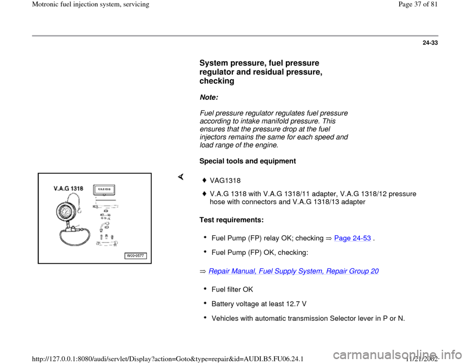
Special tools and equipment
Test requirements:
Repair Manual, Fuel Supply System, Repair Group 20
VAG1318V.A.G 1318 with V.A.G 1318/11 adapter, V.A.G 1318/12 pressure
hose with connectors and V.A.G 1318/13 adapter Fuel Pump (FP) relay OK; checking Page 24
-53
.
Fuel Pump (FP) OK, checking: Fuel filter OK Battery voltage at least 12.7 V Vehicles with automatic transmission Selector lever in P or N.
Pa
ge 37 of 81 Motronic fuel in
jection s
ystem, servicin
g
11/21/2002 htt
p://127.0.0.1:8080/audi/servlet/Dis
play?action=Goto&t
yp
e=re
pair&id=AUDI.B5.FU06.24.1
Page 38 of 81
24-34
Checking system pressure
- Open fuel filler flap briefly (pressure release).
WARNING!
Fuel system is under pressure! Before opening system, place rags
around the connection point. Then release pressure by carefully
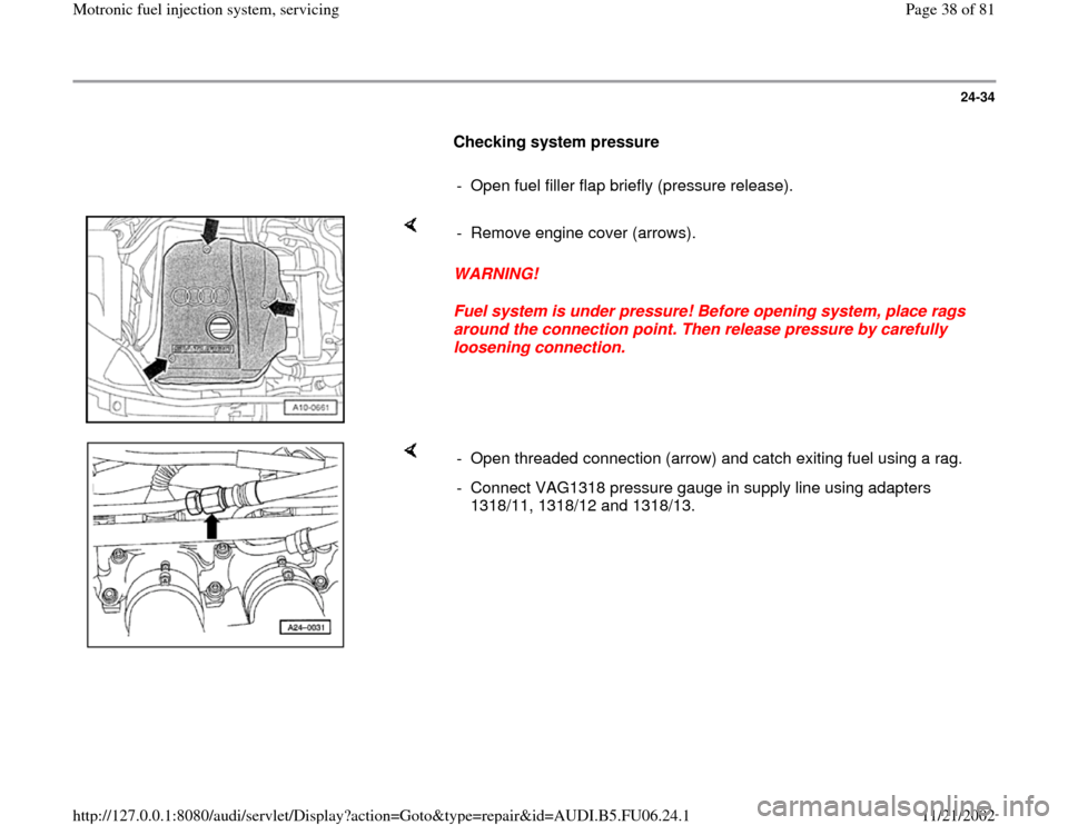
loosening connection. - Remove engine cover (arrows).
- Open threaded connection (arrow) and catch exiting fuel using a rag.
- Connect VAG1318 pressure gauge in supply line using adapters
1318/11, 1318/12 and 1318/13.
Pa
ge 38 of 81 Motronic fuel in
jection s
ystem, servicin
g
11/21/2002 htt
p://127.0.0.1:8080/audi/servlet/Dis
play?action=Goto&t
yp
e=re
pair&id=AUDI.B5.FU06.24.1
Page 39 of 81
24-35
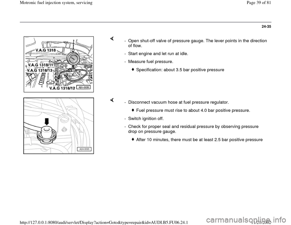
- Open shut-off valve of pressure gauge. The lever points in the direction
of flow.
- Start engine and let run at idle.
- Measure fuel pressure.
Specification: about 3.5 bar positive pressure
- Disconnect vacuum hose at fuel pressure regulator.
Fuel pressure must rise to about 4.0 bar positive pressure.
- Switch ignition off.
- Check for proper seal and residual pressure by observing pressure
drop on pressure gauge.
After 10 minutes, there must be at least 2.5 bar positive pressure
Pa
ge 39 of 81 Motronic fuel in
jection s
ystem, servicin
g
11/21/2002 htt
p://127.0.0.1:8080/audi/servlet/Dis
play?action=Goto&t
yp
e=re
pair&id=AUDI.B5.FU06.24.1