fuel pump AUDI A6 1997 C5 / 2.G ATW Engine Motronic Fuel Injection Syst
[x] Cancel search | Manufacturer: AUDI, Model Year: 1997, Model line: A6, Model: AUDI A6 1997 C5 / 2.GPages: 81, PDF Size: 1.03 MB
Page 6 of 81
24-5
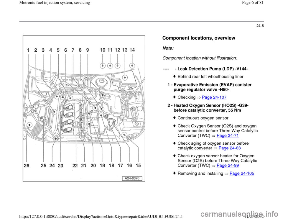
Component locations, overview
Note:
Component location without illustration:
----
- Leak Detection Pump (LDP) -V144-
Behind rear left wheelhousing liner
1 -
Evaporative Emission (EVAP) canister
purge regulator valve -N80- Checking Page 24
-107
2 -
Heated Oxygen Sensor (HO2S) -G39-
before catalytic converter, 55 Nm
Continuous oxygen sensorCheck Oxygen Sensor (O2S) and oxygen
sensor control before Three Way Catalytic
Converter (TWC) Page 24
-71
Check aging of oxygen sensor before
catalytic converter Page 24
-83
Check oxygen sensor heater for Oxygen
Sensor (O2S) before Three Way Catalytic
Converter (TWC) Page 24
-99
Removing and installing Page 24
-105
Pa
ge 6 of 81 Motronic fuel in
jection s
ystem, servicin
g
11/21/2002 htt
p://127.0.0.1:8080/audi/servlet/Dis
play?action=Goto&t
yp
e=re
pair&id=AUDI.B5.FU06.24.1
Page 10 of 81
24-9
Repair Manual, 1.8 Liter 4
-Cyl. 5V Turbo Engine
Mechanical, Engine Code(s): AEB, ATW, Repair Group 26; Secondary Air Injection (AIR) system, checking
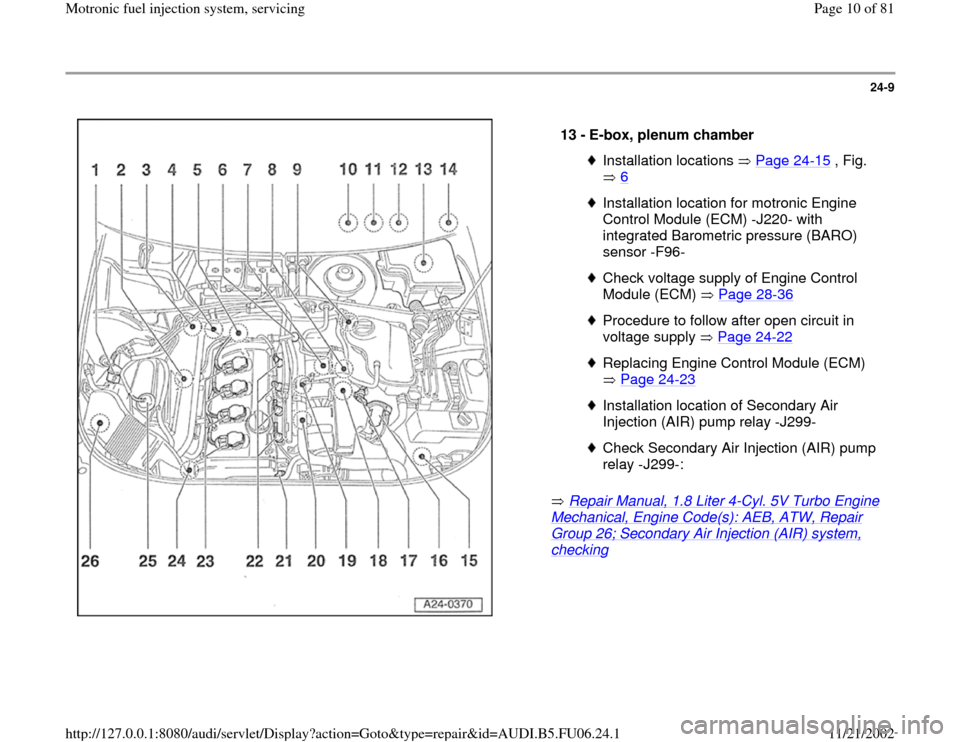
13 -
E-box, plenum chamber Installation locations Page 24
-15
, Fig.
6
Installation location for motronic Engine
Control Module (ECM) -J220- with
integrated Barometric pressure (BARO)
sensor -F96- Check voltage supply of Engine Control
Module (ECM) Page 28
-36
Procedure to follow after open circuit in
voltage supply Page 24
-22
Replacing Engine Control Module (ECM)
Page 24
-23
Installation location of Secondary Air
Injection (AIR) pump relay -J299- Check Secondary Air Injection (AIR) pump
relay -J299-:
Pa
ge 10 of 81 Motronic fuel in
jection s
ystem, servicin
g
11/21/2002 htt
p://127.0.0.1:8080/audi/servlet/Dis
play?action=Goto&t
yp
e=re
pair&id=AUDI.B5.FU06.24.1
Page 11 of 81
24-10
Repair Manual, 1.8 Liter 4
-Cyl. 5V Turbo Engine
Mechanical, Engine Code(s): AEB, ATW, Repair Group 21, Charge air system with turbocharger, checking
Installation location of motronic Engine Control
Module (ECM) power supply relay -J271-
Check motronic Engine Control Module (ECM)
power supply relay -J271- Page 28
-13
Installation location of fuse S130 for Secondary
Air Injection (AIR) pump
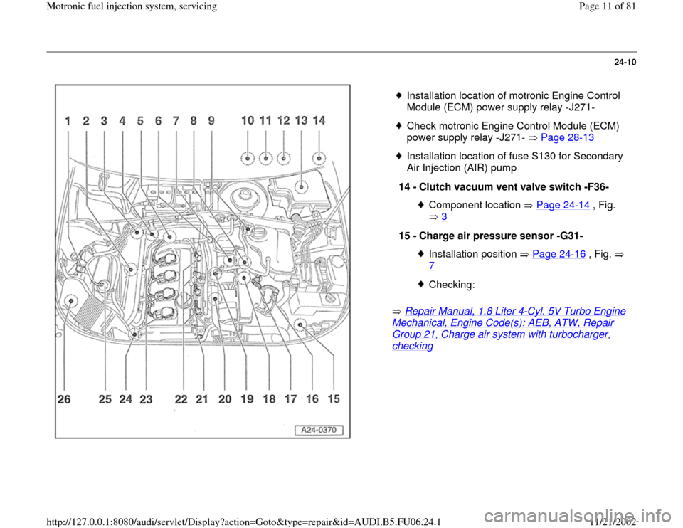
14 -
Clutch vacuum vent valve switch -F36-
Component location Page 24
-14
, Fig.
3
15 -
Charge air pressure sensor -G31-
Installation position Page 24
-16
, Fig.
7
Checking:
Pa
ge 11 of 81 Motronic fuel in
jection s
ystem, servicin
g
11/21/2002 htt
p://127.0.0.1:8080/audi/servlet/Dis
play?action=Goto&t
yp
e=re
pair&id=AUDI.B5.FU06.24.1
Page 13 of 81
24-12
Repair Manual, 1.8 Liter 4
-Cyl. 5V Turbo Engine
Mechanical, Engine Code(s): AEB, ATW, Repair Group 21, Charge air system with turbocharger, checking
Repair Manual, 1.8 Liter 4
-Cyl. 5V Turbo Engine
Mechanical, Engine Code(s): AEB, ATW, Repair Group 26; Secondary Air Injection (AIR) system, checking
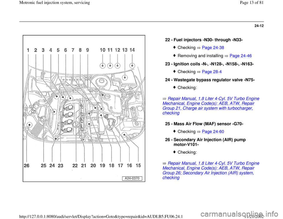
22 -
Fuel injectors -N30- through -N33- Checking Page 24
-38
Removing and installing Page 24
-46
23 -
Ignition coils -N-, -N128-, -N158-, -N163-
Checking Page 28
-4
24 -
Wastegate bypass regulator valve -N75-
Checking:
25 -
Mass Air Flow (MAF) sensor -G70-
Checking Page 24
-60
26 -
Secondary Air Injection (AIR) pump
motor-V101-
Checking:
Pa
ge 13 of 81 Motronic fuel in
jection s
ystem, servicin
g
11/21/2002 htt
p://127.0.0.1:8080/audi/servlet/Dis
play?action=Goto&t
yp
e=re
pair&id=AUDI.B5.FU06.24.1
Page 14 of 81
24-13
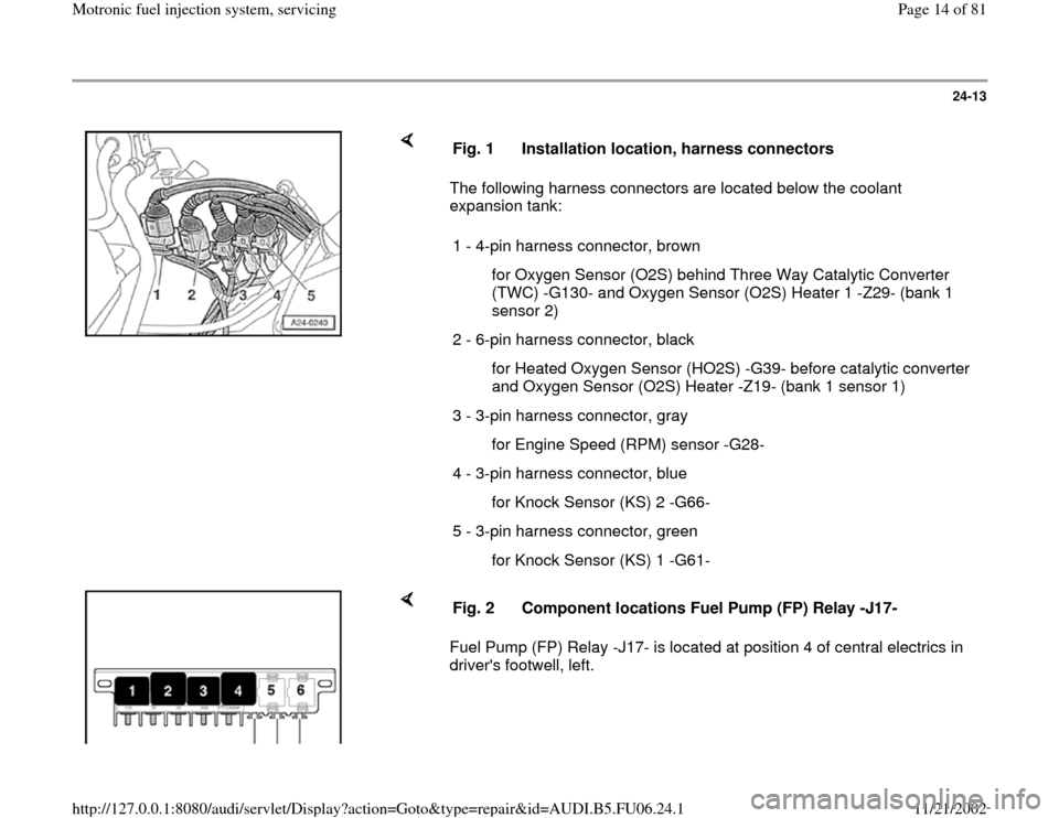
The following harness connectors are located below the coolant
expansion tank: Fig. 1 Installation location, harness connectors
1 - 4-pin harness connector, brown
for Oxygen Sensor (O2S) behind Three Way Catalytic Converter
(TWC) -G130- and Oxygen Sensor (O2S) Heater 1 -Z29- (bank 1
sensor 2)
2 - 6-pin harness connector, black
for Heated Oxygen Sensor (HO2S) -G39- before catalytic converter
and Oxygen Sensor (O2S) Heater -Z19- (bank 1 sensor 1)
3 - 3-pin harness connector, gray
for Engine Speed (RPM) sensor -G28-
4 - 3-pin harness connector, blue
for Knock Sensor (KS) 2 -G66-
5 - 3-pin harness connector, green
for Knock Sensor (KS) 1 -G61-
Fuel Pump (FP) Relay -J17- is located at position 4 of central electrics in
driver's footwell, left. Fig. 2 Component locations Fuel Pump (FP) Relay -J17-
Pa
ge 14 of 81 Motronic fuel in
jection s
ystem, servicin
g
11/21/2002 htt
p://127.0.0.1:8080/audi/servlet/Dis
play?action=Goto&t
yp
e=re
pair&id=AUDI.B5.FU06.24.1
Page 16 of 81
24-15
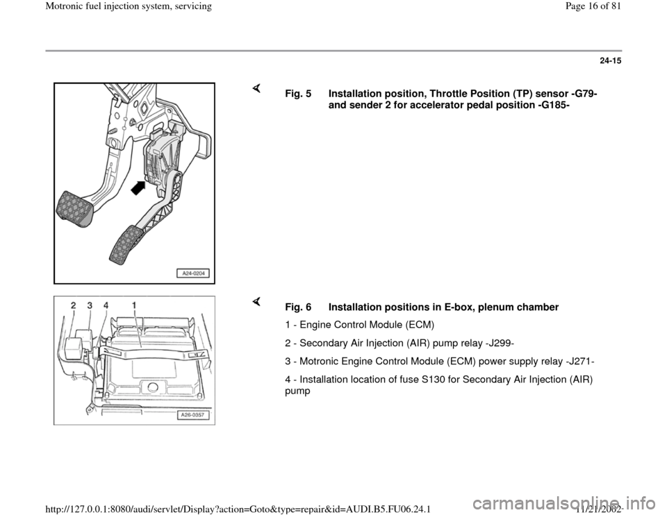
Fig. 5 Installation position, Throttle Position (TP) sensor -G79-
and sender 2 for accelerator pedal position -G185-
Fig. 6 Installation positions in E-box, plenum chamber
1 - Engine Control Module (ECM)
2 - Secondary Air Injection (AIR) pump relay -J299-
3 - Motronic Engine Control Module (ECM) power supply relay -J271-
4 - Installation location of fuse S130 for Secondary Air Injection (AIR)
pump
Pa
ge 16 of 81 Motronic fuel in
jection s
ystem, servicin
g
11/21/2002 htt
p://127.0.0.1:8080/audi/servlet/Dis
play?action=Goto&t
yp
e=re
pair&id=AUDI.B5.FU06.24.1
Page 37 of 81
24-33
System pressure, fuel pressure
regulator and residual pressure,
checking
Note:
Fuel pressure regulator regulates fuel pressure
according to intake manifold pressure. This
ensures that the pressure drop at the fuel
injectors remains the same for each speed and
load range of the engine.
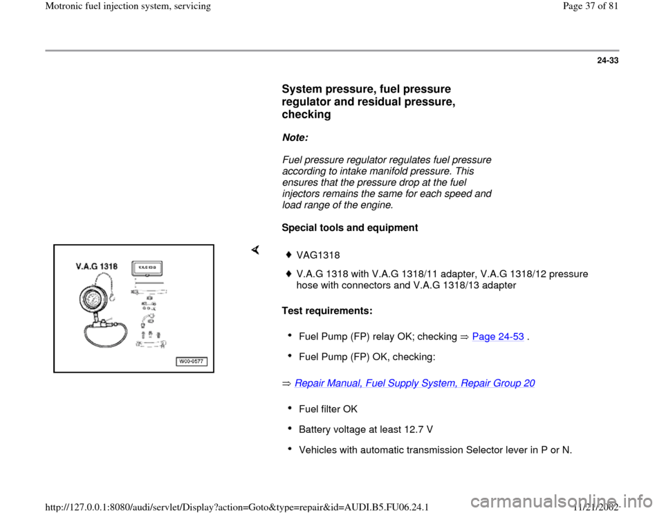
Special tools and equipment
Test requirements:
Repair Manual, Fuel Supply System, Repair Group 20
VAG1318V.A.G 1318 with V.A.G 1318/11 adapter, V.A.G 1318/12 pressure
hose with connectors and V.A.G 1318/13 adapter Fuel Pump (FP) relay OK; checking Page 24
-53
.
Fuel Pump (FP) OK, checking: Fuel filter OK Battery voltage at least 12.7 V Vehicles with automatic transmission Selector lever in P or N.
Pa
ge 37 of 81 Motronic fuel in
jection s
ystem, servicin
g
11/21/2002 htt
p://127.0.0.1:8080/audi/servlet/Dis
play?action=Goto&t
yp
e=re
pair&id=AUDI.B5.FU06.24.1
Page 40 of 81
24-36
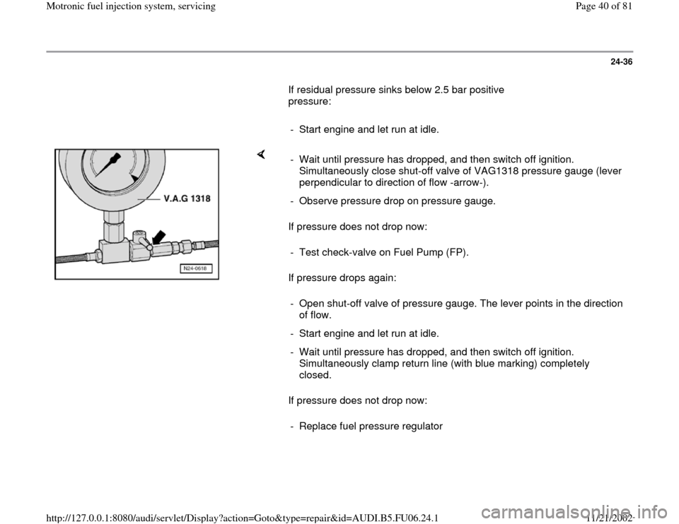
If residual pressure sinks below 2.5 bar positive
pressure:
- Start engine and let run at idle.
If pressure does not drop now:
If pressure drops again:
If pressure does not drop now: - Wait until pressure has dropped, and then switch off ignition.
Simultaneously close shut-off valve of VAG1318 pressure gauge (lever
perpendicular to direction of flow -arrow-).
- Observe pressure drop on pressure gauge.
- Test check-valve on Fuel Pump (FP).
- Open shut-off valve of pressure gauge. The lever points in the direction
of flow.
- Start engine and let run at idle.
- Wait until pressure has dropped, and then switch off ignition.
Simultaneously clamp return line (with blue marking) completely
closed.
- Replace fuel pressure regulator
Pa
ge 40 of 81 Motronic fuel in
jection s
ystem, servicin
g
11/21/2002 htt
p://127.0.0.1:8080/audi/servlet/Dis
play?action=Goto&t
yp
e=re
pair&id=AUDI.B5.FU06.24.1
Page 44 of 81
24-40
Checking voltage supply
Test requirements:
Fuse for fuel injectors OK
Electrical Wiring Diagrams, Troubleshooting &
Component Locations
Fuel Pump (FP) relay OK; checking Page 24
-53
.
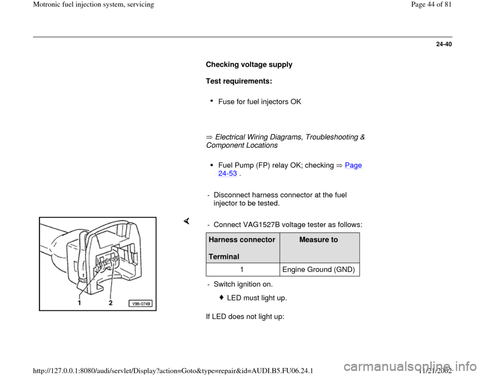
- Disconnect harness connector at the fuel
injector to be tested.
If LED does not light up: - Connect VAG1527B voltage tester as follows:Harness connector
Terminal
Measure to
1 Engine Ground (GND)
- Switch ignition on.
LED must light up.
Pa
ge 44 of 81 Motronic fuel in
jection s
ystem, servicin
g
11/21/2002 htt
p://127.0.0.1:8080/audi/servlet/Dis
play?action=Goto&t
yp
e=re
pair&id=AUDI.B5.FU06.24.1
Page 55 of 81
24-50
Test requirement:
Fuel pressure OK, checking Page 24
-33
.
Test sequence
- Remove fuel distributor including fuel injectors
from intake manifold Page 24
-46
. Fuel lines
remain connected.
- Connect VAG1598/31 test box at wiring harness
to Engine Control Module (ECM), do not connect
ECM Page 24
-19
.
Checking Proper Seal
- Bridge terminals 1 and 65 at test box using wires
from VAG1594A adapter test kit.
- Switch ignition on.
Fuel Pump (FP) must run.
- Check proper seal of fuel injectors (visual
inspection). With Fuel Pump (FP) running, only 1
to 2 drops per minute may drip out per injector.
-
If fuel loss is greater, stop Fuel Pump (FP) from
Pa
ge 55 of 81 Motronic fuel in
jection s
ystem, servicin
g
11/21/2002 htt
p://127.0.0.1:8080/audi/servlet/Dis
play?action=Goto&t
yp
e=re
pair&id=AUDI.B5.FU06.24.1