check engine AUDI A6 1999 C5 / 2.G ATQ Engine Motronic Injection System Servicing Workshop Manual
[x] Cancel search | Manufacturer: AUDI, Model Year: 1999, Model line: A6, Model: AUDI A6 1999 C5 / 2.GPages: 78, PDF Size: 1 MB
Page 3 of 78
24-2
It is possible that the control module will
recognize a malfunction and store a DTC during
some tests. After completing all tests and
repairs, DTC memory should therefore be
checked and erased if necessary. Readiness
code must be generated after DTC memory is
erased Page 01
-82
.
Always switch ignition off before cleaning
engine.
The battery should only be disconnected and
reconnected when the ignition is turned off,
since otherwise the Engine Control Module
(ECM) can be damaged.
WARNING!
Fuel system is under pressure! Place a cloth
around the connection point before opening
system. Then release pressure by carefully
loosening connection point.
Pa
ge 3 of 78 Motronic in
jection s
ystem, servicin
g
11/23/2002 htt
p://127.0.0.1:8080/audi/servlet/Dis
play?action=Goto&t
yp
e=re
pair&id=AUDI.B5.FU05.24.1
Page 10 of 78
24-8
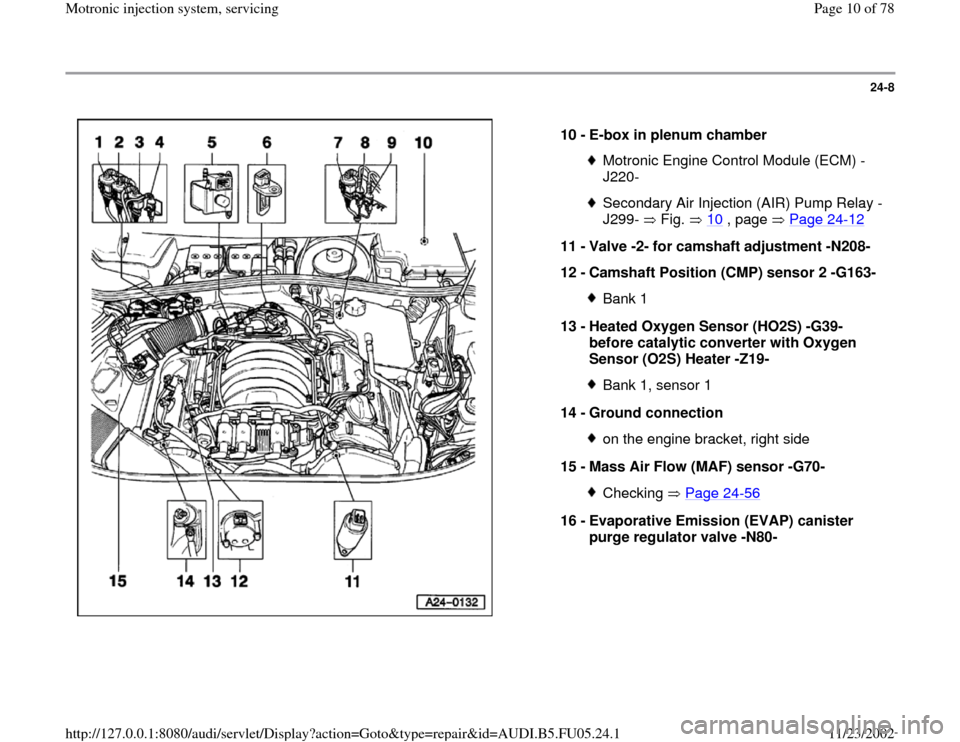
10 -
E-box in plenum chamber
Motronic Engine Control Module (ECM) -
J220- Secondary Air Injection (AIR) Pump Relay -
J299- Fig. 10
, page Page 24
-12
11 -
Valve -2- for camshaft adjustment -N208-
12 -
Camshaft Position (CMP) sensor 2 -G163-
Bank 1
13 -
Heated Oxygen Sensor (HO2S) -G39-
before catalytic converter with Oxygen
Sensor (O2S) Heater -Z19- Bank 1, sensor 1
14 -
Ground connection on the engine bracket, right side
15 -
Mass Air Flow (MAF) sensor -G70- Checking Page 24
-56
16 -
Evaporative Emission (EVAP) canister
purge regulator valve -N80-
Pa
ge 10 of 78 Motronic in
jection s
ystem, servicin
g
11/23/2002 htt
p://127.0.0.1:8080/audi/servlet/Dis
play?action=Goto&t
yp
e=re
pair&id=AUDI.B5.FU05.24.1
Page 11 of 78
24-9
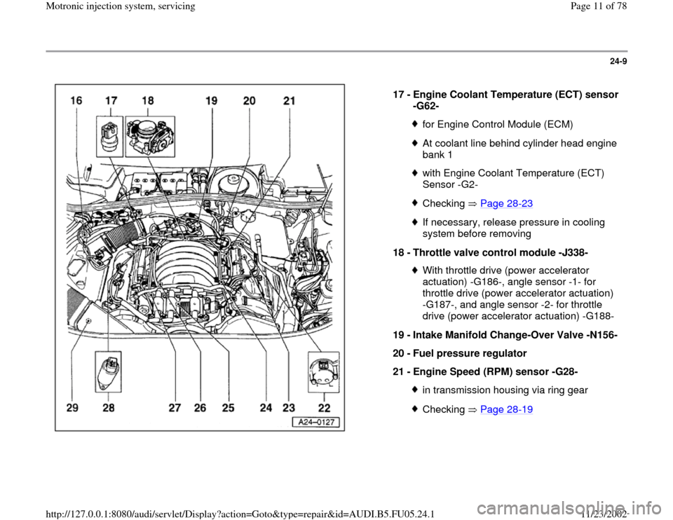
17 -
Engine Coolant Temperature (ECT) sensor
-G62-
for Engine Control Module (ECM)At coolant line behind cylinder head engine
bank 1 with Engine Coolant Temperature (ECT)
Sensor -G2- Checking Page 28
-23
If necessary, release pressure in cooling
system before removing
18 -
Throttle valve control module -J338- With throttle drive (power accelerator
actuation) -G186-, angle sensor -1- for
throttle drive (power accelerator actuation)
-G187-, and angle sensor -2- for throttle
drive (power accelerator actuation) -G188-
19 -
Intake Manifold Change-Over Valve -N156-
20 -
Fuel pressure regulator
21 -
Engine Speed (RPM) sensor -G28- in transmission housing via ring gearChecking Page 28
-19
Pa
ge 11 of 78 Motronic in
jection s
ystem, servicin
g
11/23/2002 htt
p://127.0.0.1:8080/audi/servlet/Dis
play?action=Goto&t
yp
e=re
pair&id=AUDI.B5.FU05.24.1
Page 22 of 78
24-20
Important note:
After re-connecting the Engine Control Module (ECM), the following work
steps must be performed:
- Check DTC memory and erase it if necessary Page 01
-15
.
- Perform adaptation of the Throttle Valve Control Module -J338- Page
24
-142
.
Note:
In the first adaptation phase during engine basic setting, it is possible that
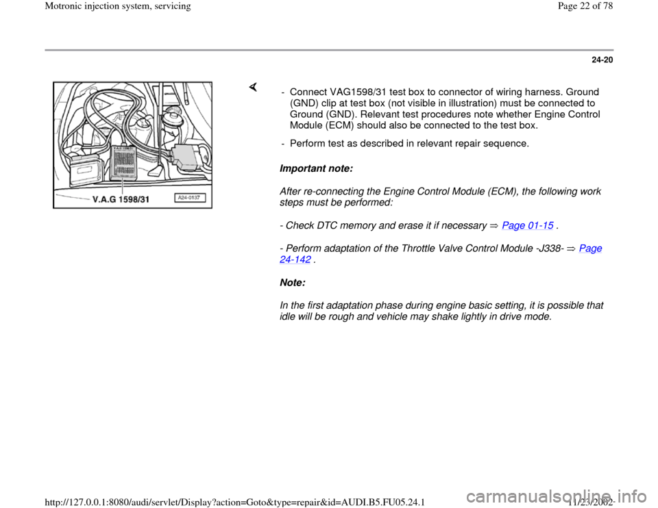
idle will be rough and vehicle may shake lightly in drive mode. - Connect VAG1598/31 test box to connector of wiring harness. Ground
(GND) clip at test box (not visible in illustration) must be connected to
Ground (GND). Relevant test procedures note whether Engine Control
Module (ECM) should also be connected to the test box.
- Perform test as described in relevant repair sequence.
Pa
ge 22 of 78 Motronic in
jection s
ystem, servicin
g
11/23/2002 htt
p://127.0.0.1:8080/audi/servlet/Dis
play?action=Goto&t
yp
e=re
pair&id=AUDI.B5.FU05.24.1
Page 25 of 78
24-23
Installing
Installation is reverse of removal, noting the following:
Important note:
After installing new Engine Control Module (ECM), the following work
steps must be performed:
- Check DTC memory and erase it if necessary Page 01
-15
.
- Perform adaptation of the Throttle Valve Control Module -J338- Page
24
-142
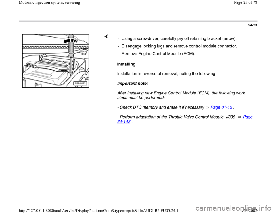
. - Using a screwdriver, carefully pry off retaining bracket (arrow).
- Disengage locking lugs and remove control module connector.
- Remove Engine Control Module (ECM).
Pa
ge 25 of 78 Motronic in
jection s
ystem, servicin
g
11/23/2002 htt
p://127.0.0.1:8080/audi/servlet/Dis
play?action=Goto&t
yp
e=re
pair&id=AUDI.B5.FU05.24.1
Page 26 of 78
24-24
- Observe notes for coding new Engine Control
Module (ECM) Page 01
-71
.
- For vehicles with cruise control (discernable at
steering column), switch this free in ECM:
Repair Manual, Electrical Equipment, Repair
Group 01; On Board Diagnostic (OBD) of cruise control system; Cruise control system, checking
- Adapt immobilizer to Engine Control Module
(ECM):
Repair Manual, Electrical Equipment, Repair
Group 01; On Board Diagnostic (OBD) of immobilizer after replacing Engine Control Module (ECM)
- For vehicles with automatic transmission, the
kick down function must be learned Page 24
-
161
.
- Generate readiness code Page 01
-82
.
Note:
In the first adaptation phase during engine basic
setting, it is possible that idle will be rough and
vehicle may shake lightly in drive mode.
Pa
ge 26 of 78 Motronic in
jection s
ystem, servicin
g
11/23/2002 htt
p://127.0.0.1:8080/audi/servlet/Dis
play?action=Goto&t
yp
e=re
pair&id=AUDI.B5.FU05.24.1
Page 28 of 78
24-26
Notes:
Idle speed cannot be adjusted.
Idle speed is checked during basic setting of
the engine.
During basic setting, the Evaporative Emission
(EVAP) canister purge regulator valve (EVAP
valve -N80-) is closed and the A/C compressor
is switched off
Test sequence
- Check DTC Memory Page 01
-15
. There must
not be any DTCs stored, repair malfunctions if
necessary, erase DTC memory, switch engine
off and start again, road test vehicle and check
DTC memory again as a control measure.
- Let engine continue to run at idle.
CAUTION!
The electric cooling fan must not run. Rapid data transfer
HELP
Select function XX
When indicated on display:
- Press buttons -0- and -4- to select "Initiate basic setting" and press -Q-
button to confirm input.
Pa
ge 28 of 78 Motronic in
jection s
ystem, servicin
g
11/23/2002 htt
p://127.0.0.1:8080/audi/servlet/Dis
play?action=Goto&t
yp
e=re
pair&id=AUDI.B5.FU05.24.1
Page 29 of 78
24-27
Basic Settin
g
Q
Input display group number XXX
When indicated on display:
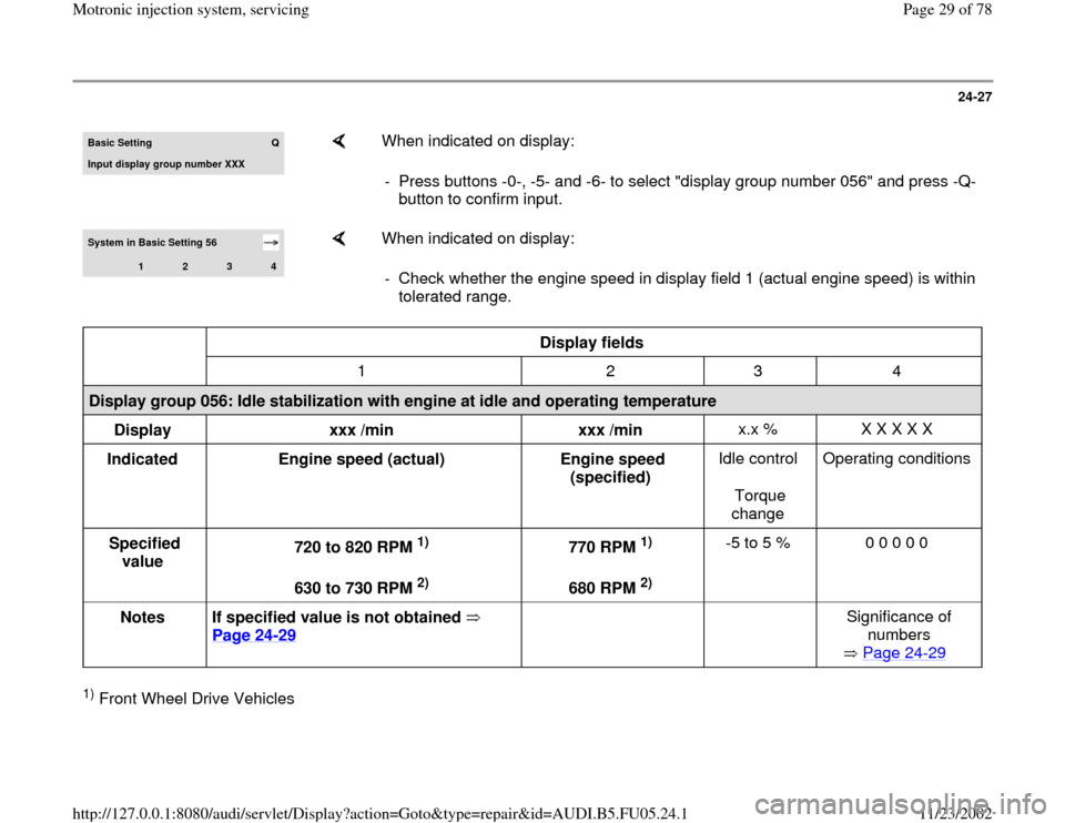
- Press buttons -0-, -5- and -6- to select "display group number 056" and press -Q-
button to confirm input.
System in Basic Setting 56
1
2
3
4
When indicated on display:
- Check whether the engine speed in display field 1 (actual engine speed) is within
tolerated range.
Display fields
1 2 3 4
Display group 056: Idle stabilization with engine at idle and operating temperature
Display
xxx /min
xxx /min x.x % X X X X X
Indicated
Engine speed (actual)
Engine speed
(specified) Idle control
Torque
change Operating conditions
Specified
value 720 to 820 RPM
1)
630 to 730 RPM 2) 770 RPM
1)
680 RPM 2) -5 to 5 % 0 0 0 0 0
Notes
If specified value is not obtained
Page 24
-29
Significance of
numbers
Page 24
-29
1) Front Wheel Drive Vehicles
Pa
ge 29 of 78 Motronic in
jection s
ystem, servicin
g
11/23/2002 htt
p://127.0.0.1:8080/audi/servlet/Dis
play?action=Goto&t
yp
e=re
pair&id=AUDI.B5.FU05.24.1
Page 31 of 78
24-28
Notes:
Engine speed in display field 1 (actual engine
speed) is the current engine speed.
Engine speed in display field 2 (specified
engine speed) is a theoretical engine speed
calculated by the ECM.
At idle, the ECM always attempts to adapt the
engine speed (actual) to the specified engine
speed (specified).
This means that the engine speed (actual) must
always approximately match the engine speed
(specified) at idle.
Display fields 3 and 4 provide information, but
are not relevant for checking idle speed.
If specified value is obtained:
-
Press button.
Rapid data transfer
HELP
Select function XX
Indicated on display (function selection):
If specified value is not obtained:
- Check DTC memory again Page 01
-15
.
Pa
ge 31 of 78 Motronic in
jection s
ystem, servicin
g
11/23/2002 htt
p://127.0.0.1:8080/audi/servlet/Dis
play?action=Goto&t
yp
e=re
pair&id=AUDI.B5.FU05.24.1
Page 35 of 78
24-30
Fuel pressure regulator and residual
pressure, checking
Note:
Fuel pressure regulator regulates fuel pressure
according to intake manifold pressure. This
ensures that the pressure drop at the fuel
injectors remains the same for each speed and
load range of the engine.
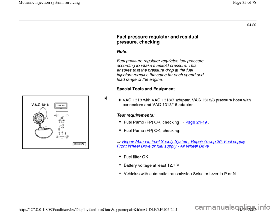
Special Tools and Equipment
Test requirements:
Repair Manual, Fuel Supply System, Repair Group 20; Fuel supply Front Wheel Drive or fuel supply
- All Wheel Drive
VAG 1318 with VAG 1318/7 adapter, VAG 1318/8 pressure hose with
connectors and VAG 1318/15 adapter Fuel Pump (FP) OK, checking Page 24
-49
.
Fuel Pump (FP) OK, checking: Fuel filter OK Battery voltage at least 12.7 V Vehicles with automatic transmission Selector lever in P or N.
Pa
ge 35 of 78 Motronic in
jection s
ystem, servicin
g
11/23/2002 htt
p://127.0.0.1:8080/audi/servlet/Dis
play?action=Goto&t
yp
e=re
pair&id=AUDI.B5.FU05.24.1