steering wheel AUDI A6 2001 C5 / 2.G 01V Transmission Remove And Install Workshop Manual
[x] Cancel search | Manufacturer: AUDI, Model Year: 2001, Model line: A6, Model: AUDI A6 2001 C5 / 2.GPages: 64, PDF Size: 1.44 MB
Page 3 of 64
37-73
Additional information
Repair Manual, Suspension, Wheels,
Steering
Repair Manual, Electrical Equipment
Repair Manual, Engine Mechanical
- Note radio code (for vehicles equipped with
coded anti-theft radio).
- Disconnect Ground (GND) strap from battery.
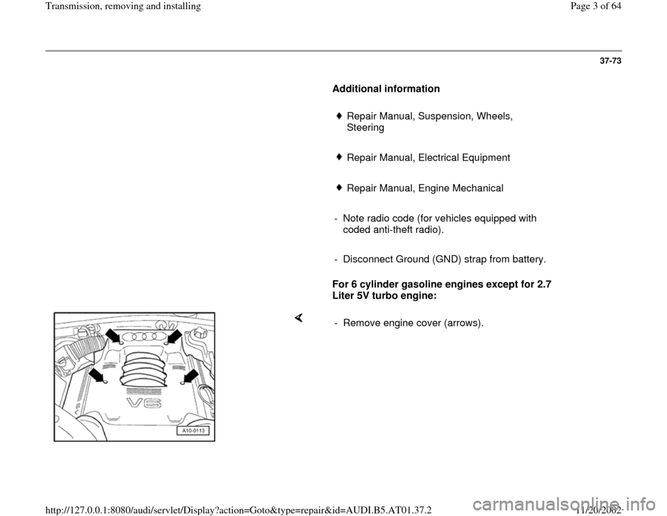
For 6 cylinder gasoline engines except for 2.7
Liter 5V turbo engine:
- Remove engine cover (arrows).
Pa
ge 3 of 64 Transmission, removin
g and installin
g
11/20/2002 htt
p://127.0.0.1:8080/audi/servlet/Dis
play?action=Goto&t
yp
e=re
pair&id=AUDI.B5.AT01.37.2
Page 7 of 64
37-77
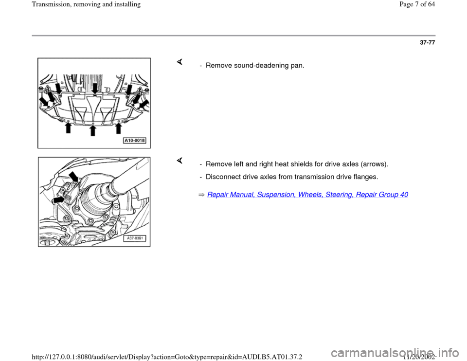
- Remove sound-deadening pan.
Repair Manual, Suspension, Wheels, Steering, Repair Group 40
- Remove left and right heat shields for drive axles (arrows).
- Disconnect drive axles from transmission drive flanges.
Pa
ge 7 of 64 Transmission, removin
g and installin
g
11/20/2002 htt
p://127.0.0.1:8080/audi/servlet/Dis
play?action=Goto&t
yp
e=re
pair&id=AUDI.B5.AT01.37.2
Page 24 of 64
37-94
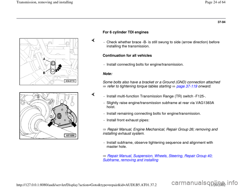
For 6 cylinder TDI engines
Continuation for all vehicles
Note:
Some bolts also have a bracket or a Ground (GND) connection attached
refer to tightening torque tables starting page 37
-119
onward. - Check whether brace -B- is still swung to side (arrow direction) before
installing the transmission.
- Install connecting bolts for engine/transmission.
Repair Manual, Engine Mechanical, Repair Group 26; removing and
installing exhaust system.
Repair Manual, Suspension, Wheels, Steering, Repair Group 40;
Subframe, removing and installing
- Install multi-function Transmission Range (TR) switch -F125-.
- Slightly raise engine/transmission subframe at rear via VAG1383A
hoist.
- Install remaining connecting bolts for engine/transmission.
- Install front exhaust pipes:
- Install subframe, observe tightening sequence and alignment with
master hole.
Pa
ge 24 of 64 Transmission, removin
g and installin
g
11/20/2002 htt
p://127.0.0.1:8080/audi/servlet/Dis
play?action=Goto&t
yp
e=re
pair&id=AUDI.B5.AT01.37.2
Page 25 of 64

37-95
- Only perform vehicle alignment if necessary.
Repair Manual, Suspension, Wheels,
Steering, Repair Group 44; Vehicle alignment
- Install transmission supports at left and right with
transmission mount page 37
-125
Bolt torque converter to drive plate
For vehicles with hex bolts: - Remove bolt -A- after transmission is bolted to engine.
- Apply corrosion protection to contact surface between bolt -A- and oil
pan.
- Bolt torque converter to drive plate via 3 bolts using special tool V175
(turn crank shaft an additional 1/3 turn every time).
Pa
ge 25 of 64 Transmission, removin
g and installin
g
11/20/2002 htt
p://127.0.0.1:8080/audi/servlet/Dis
play?action=Goto&t
yp
e=re
pair&id=AUDI.B5.AT01.37.2
Page 26 of 64
37-96
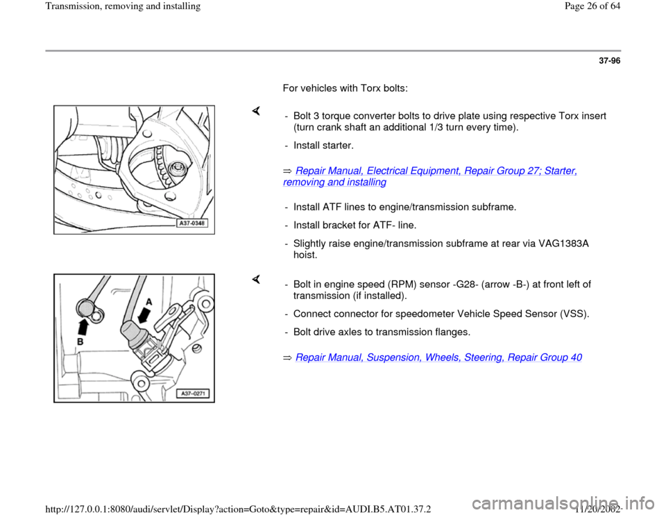
For vehicles with Torx bolts:
Repair Manual, Electrical Equipment, Repair Group 27; Starter,
removing and installing
- Bolt 3 torque converter bolts to drive plate using respective Torx insert
(turn crank shaft an additional 1/3 turn every time).
- Install starter.
- Install ATF lines to engine/transmission subframe.
- Install bracket for ATF- line.
- Slightly raise engine/transmission subframe at rear via VAG1383A
hoist.
Repair Manual, Suspension, Wheels, Steering, Repair Group 40
- Bolt in engine speed (RPM) sensor -G28- (arrow -B-) at front left of
transmission (if installed).
- Connect connector for speedometer Vehicle Speed Sensor (VSS).
- Bolt drive axles to transmission flanges.
Pa
ge 26 of 64 Transmission, removin
g and installin
g
11/20/2002 htt
p://127.0.0.1:8080/audi/servlet/Dis
play?action=Goto&t
yp
e=re
pair&id=AUDI.B5.AT01.37.2
Page 33 of 64
37-103
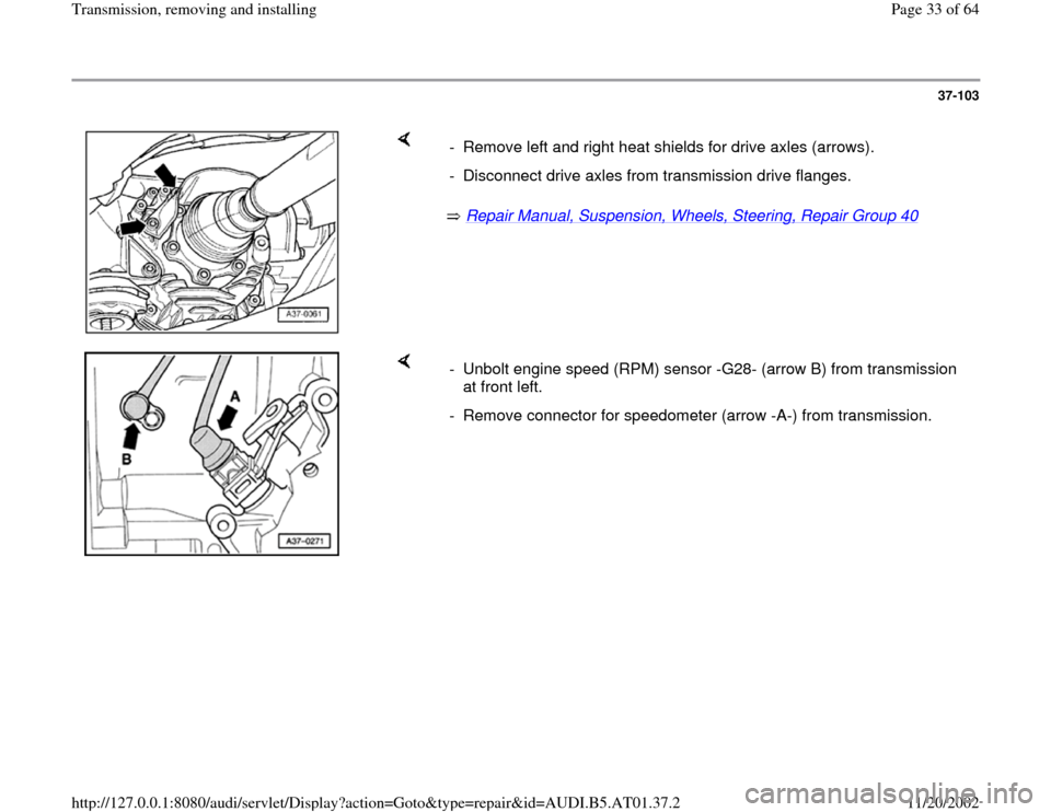
Repair Manual, Suspension, Wheels, Steering, Repair Group 40
- Remove left and right heat shields for drive axles (arrows).
- Disconnect drive axles from transmission drive flanges.
- Unbolt engine speed (RPM) sensor -G28- (arrow B) from transmission
at front left.
- Remove connector for speedometer (arrow -A-) from transmission.
Pa
ge 33 of 64 Transmission, removin
g and installin
g
11/20/2002 htt
p://127.0.0.1:8080/audi/servlet/Dis
play?action=Goto&t
yp
e=re
pair&id=AUDI.B5.AT01.37.2
Page 35 of 64
37-105
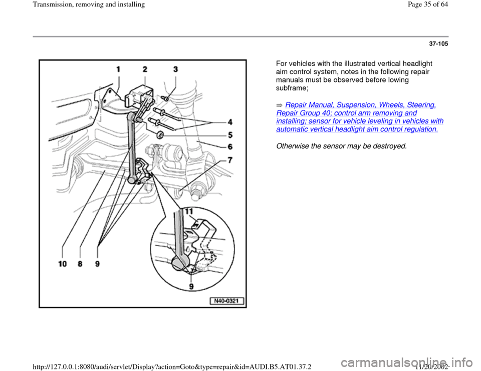
For vehicles with the illustrated vertical headlight
aim control system, notes in the following repair
manuals must be observed before lowing
subframe;
Repair Manual, Suspension, Wheels, Steering,
Repair Group 40; control arm removing and installing; sensor for vehicle leveling in vehicles with automatic vertical headlight aim control regulation.
Otherwise the sensor may be destroyed.
Pa
ge 35 of 64 Transmission, removin
g and installin
g
11/20/2002 htt
p://127.0.0.1:8080/audi/servlet/Dis
play?action=Goto&t
yp
e=re
pair&id=AUDI.B5.AT01.37.2
Page 37 of 64
37-107
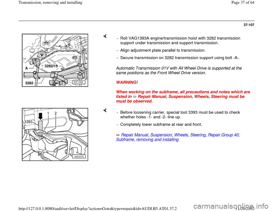
Automatic Transmission 01V with All Wheel Drive is supported at the
same positions as the Front Wheel Drive version.
WARNING!
When working on the subframe, all precautions and notes which are
listed in Repair Manual, Suspension, Wheels, Steering must be
must be observed. - Roll VAG1383A engine/transmission hoist with 3282 transmission
support under transmission and support transmission.
- Align adjustment plate parallel to transmission.
- Secure transmission on 3282 transmission support using bolt -A-.
Repair Manual, Suspension, Wheels, Steering, Repair Group 40;
Subframe, removing and installing
- Before loosening carrier, special tool 3393 must be used to check
whether holes -1- and -2- line up.
- Completely lower subframe at rear and front.
Pa
ge 37 of 64 Transmission, removin
g and installin
g
11/20/2002 htt
p://127.0.0.1:8080/audi/servlet/Dis
play?action=Goto&t
yp
e=re
pair&id=AUDI.B5.AT01.37.2
Page 47 of 64
37-117
Repair Manual, Suspension, Wheels, Steering, Repair Group 40;
Subframe, removing and installing
Repair Manual, Suspension, Wheels, Steering, Repair Group 44,
Vehicle alignment
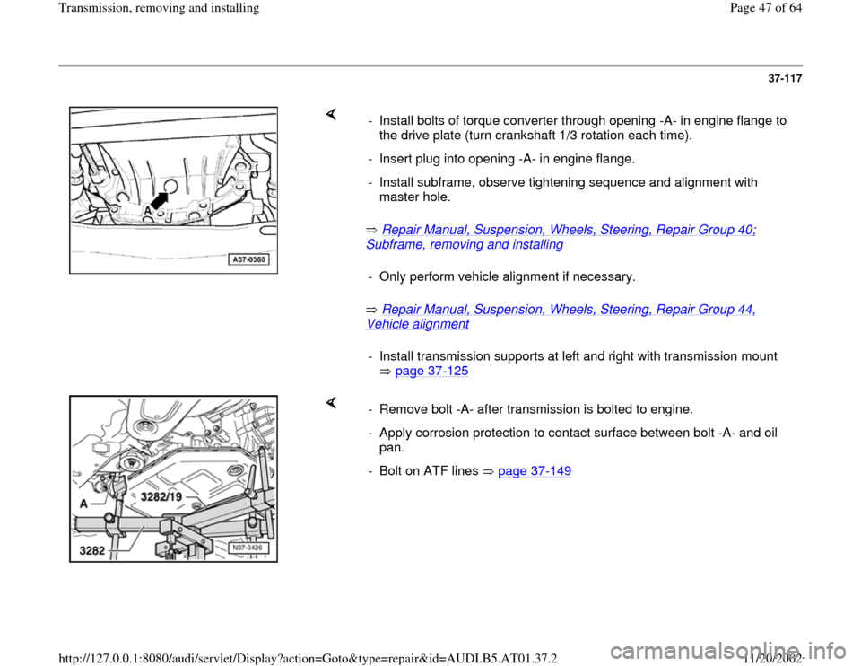
- Install bolts of torque converter through opening -A- in engine flange to
the drive plate (turn crankshaft 1/3 rotation each time).
- Insert plug into opening -A- in engine flange.
- Install subframe, observe tightening sequence and alignment with
master hole.
- Only perform vehicle alignment if necessary.- Install transmission supports at left and right with transmission mount
page 37
-125
- Remove bolt -A- after transmission is bolted to engine.
- Apply corrosion protection to contact surface between bolt -A- and oil
pan.
- Bolt on ATF lines page 37
-149
Pa
ge 47 of 64 Transmission, removin
g and installin
g
11/20/2002 htt
p://127.0.0.1:8080/audi/servlet/Dis
play?action=Goto&t
yp
e=re
pair&id=AUDI.B5.AT01.37.2
Page 48 of 64
37-118
- Bolt drive axles to transmission flanges.
Repair Manual, Suspension, Wheels,
Steering, Repair Group 40
- Bolt driveshaft to transmission flange page
39
-79
, Driveshaft, removing and installing.
- After connecting battery, enter anti-theft code for
radio.
Radio operating manual
- Check adjustment of selector lever cable
page 37
-45
.
- Check gear oil in final drive with transmission
installed page 39
-1 .
- Then check ATF level and top off Page 37
-
133
onward.
- Fully close power windows to stop.
Pa
ge 48 of 64 Transmission, removin
g and installin
g
11/20/2002 htt
p://127.0.0.1:8080/audi/servlet/Dis
play?action=Goto&t
yp
e=re
pair&id=AUDI.B5.AT01.37.2