AUDI A6 2005 C5 / 2.G Electrics System Training Manual
Manufacturer: AUDI, Model Year: 2005, Model line: A6, Model: AUDI A6 2005 C5 / 2.GPages: 92, PDF Size: 4.42 MB
Page 41 of 92

Downloaded from www.Manualslib.com manuals search engine 43
Emergency function
The software for the control unit for on-board power
supply can be used to implement emergency
functions. If a fault is detected in the rotary light
switch or if there is an open circuit in the line to the
rotary light switch, the control unit for on-board
power supply switches the driving light on.
Other functionalities
In addition to the master functions, the following
functions are also available in the control unit for
on-board power supply.
– Steering column adjustment
– Footwell lighting
– Selector gate lighting
– Direction indicator control, front and side
– Signal horn activation
– Windscreen washer pump activation
– Steering column memory
Versi on s
There are three functional versions of the control
unit for on-board power supply:
– Low-Line version (with no electric steering
column adjustment, no xenon, no daytime
driving lights)
– Mid-Line version (with no electric steering
column adjustment, with xenon and daytime
driving lights)
– High-Line version (with electric steering column
adjustment, xenon and daytime driving lights)
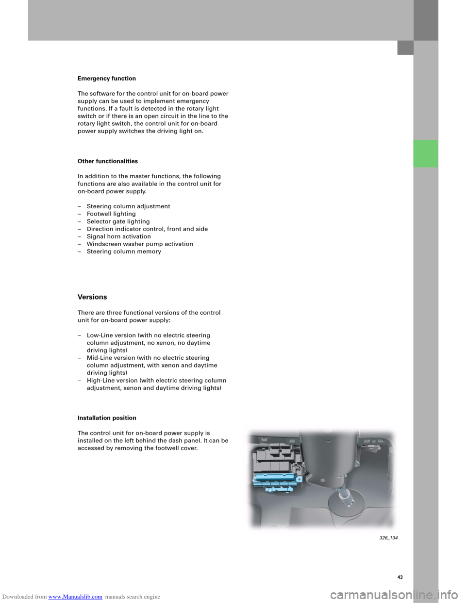
Installation position
The control unit for on-board power supply is
installed on the left behind the dash panel. It can be
accessed by removing the footwell cover.
326_134
Page 42 of 92

Downloaded from www.Manualslib.com manuals search engine 44
Function diagram
Convenience electrics
E1 Light switch
E3 Hazard warning light switch
E7 Fog light switch
E18 Switch for rear fog light
F4 Reversing light switch
F266 Contact switch for bonnet
G357 Sender for vertical steering column adjustm.
G358 Sender for axial steering column adjustment
G397 Sensor for rain and light detection
G474 Sensor for pivot module position, left
G475 Sensor for pivot module position, right
H2 High-pitch horn
H7 Low-pitch horn
J4 Relay for dual-pitch horn
J400 Control unit for wiper motor
J431 Control unit for headlight range control
J519 Control unit for on-board power supply
J667 Power module for left headlight
J668 Power module for right headlightK4 Indicator light for parking light
K6 Indicator light for hazard warning lights
K13 Indicator light for rear fog light
K17 Indicator light for fog lights
L9 Lamp for light-switch lighting
L13 Gas discharge light, left
L14 Gas discharge light, right
L22 Lamp for left fog light
L23 Lamp for right fog light
L174 Lamp for daytime driving light, left
L175 Lamp for daytime driving light, right
M1 Lamp for parking light, left
M3 Lamp for parking light, right
M5 Lamp for direction indicator light, front left
M7 Lamp for direction indicator light, front right
M18 Lamp for side direction indicator light, left
M19 Lamp for side direction indicator light, right
Page 43 of 92

Downloaded from www.Manualslib.com manuals search engine 45
N395 Magnet for cover adjustment,
left headlight
N396 Magnet for cover adjustment,
right headlight
V5 Windscreen washer pump
V48 Left control motor for headlight range control
V49 Right control motor for headlight range
control
V123 Motor for vertical steering column
adjustment
V124 Motor for axial steering column adjustment
V318 Control motor for dynamic cornering light,
left
V319 Control motor for dynamic cornering light,
right
W9 Footwell light, left
W10 Footwell light, rightAdditional signals
1Terminal 58
2 Terminal 58s
3CAN Drive High
4CAN Drive Low
5CAN Convenience High
6CAN Convenience Low
326_111
Page 44 of 92

Downloaded from www.Manualslib.com manuals search engine 46
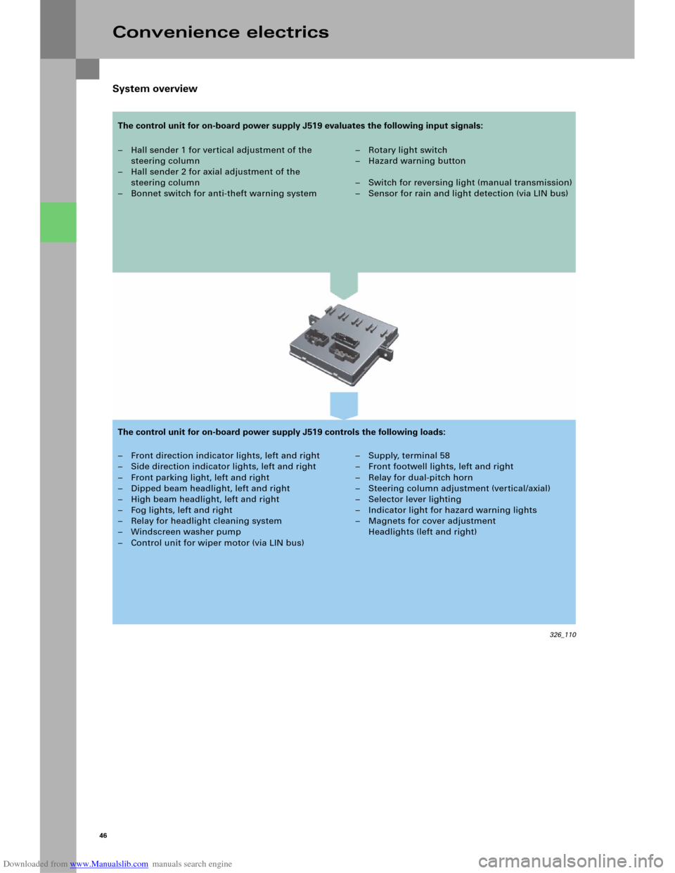
System overview
Convenience electrics
– Hall sender 1 for vertical adjustment of the
steering column
– Hall sender 2 for axial adjustment of the
steering column
– Bonnet switch for anti-theft warning system–Rotary light switch
–Hazard warning button
– Switch for reversing light (manual transmission)
– Sensor for rain and light detection (via LIN bus)
– Front direction indicator lights, left and right
– Side direction indicator lights, left and right
– Front parking light, left and right
– Dipped beam headlight, left and right
– High beam headlight, left and right
– Fog lights, left and right
– Relay for headlight cleaning system
– Windscreen washer pump
– Control unit for wiper motor (via LIN bus)– Supply, terminal 58
– Front footwell lights, left and right
– Relay for dual-pitch horn
– Steering column adjustment (vertical/axial)
– Selector lever lighting
– Indicator light for hazard warning lights
– Magnets for cover adjustment
Headlights (left and right)
326_110
The control unit for on-board power supply J519 evaluates the following input signals:
The control unit for on-board power supply J519 controls the following loads:
Page 45 of 92

Downloaded from www.Manualslib.com manuals search engine 47
Diagnosis
Basic settings
After the control unit for on-board power
supply J519 or the steering column or the switch for
steering column adjustment E167 is replaced, a
basic setting in axial and vertical position must be
implemented for the steering column.
Actuator test
An actuator test can be used to carry out the
following checks:
– Indicator light for hazard warning lights K6
– Lamp for parking light, left M1
– Lamp for parking light, right M3
– Lamp for dipped beam headlight, left M29
– Lamp for dipped beam headlight, right M31
– Lamp for high beam headlight, left M30
– Lamp for high beam headlight, right M32
– Lamp for left fog light L22
– Lamp for right fog light L23
– Lamp for daytime driving light, left L174
– Lamp for daytime driving light, right L175
– Direction indicator lights, left
– Direction indicator lights, right
– Footwell light, left W9
– Footwell light, right W10
– Wiper, top turning position
– Wiper, bottom turning position
– Windscreen washer pump V5
– Relay for dual-pitch horn
–Terminal 58
Coding
The control unit for on-board power supply J519 can
be coded for the functions
–Daytime driving light,
– Driving light assistant,
– Headlight type,
– Footwell lighting and
–Country versions
using the diagnosis tester.
Note
The actuator test can be performed either
sequentially (in sequence) or selectively
(individual selection).
Page 46 of 92

Downloaded from www.Manualslib.com manuals search engine 48
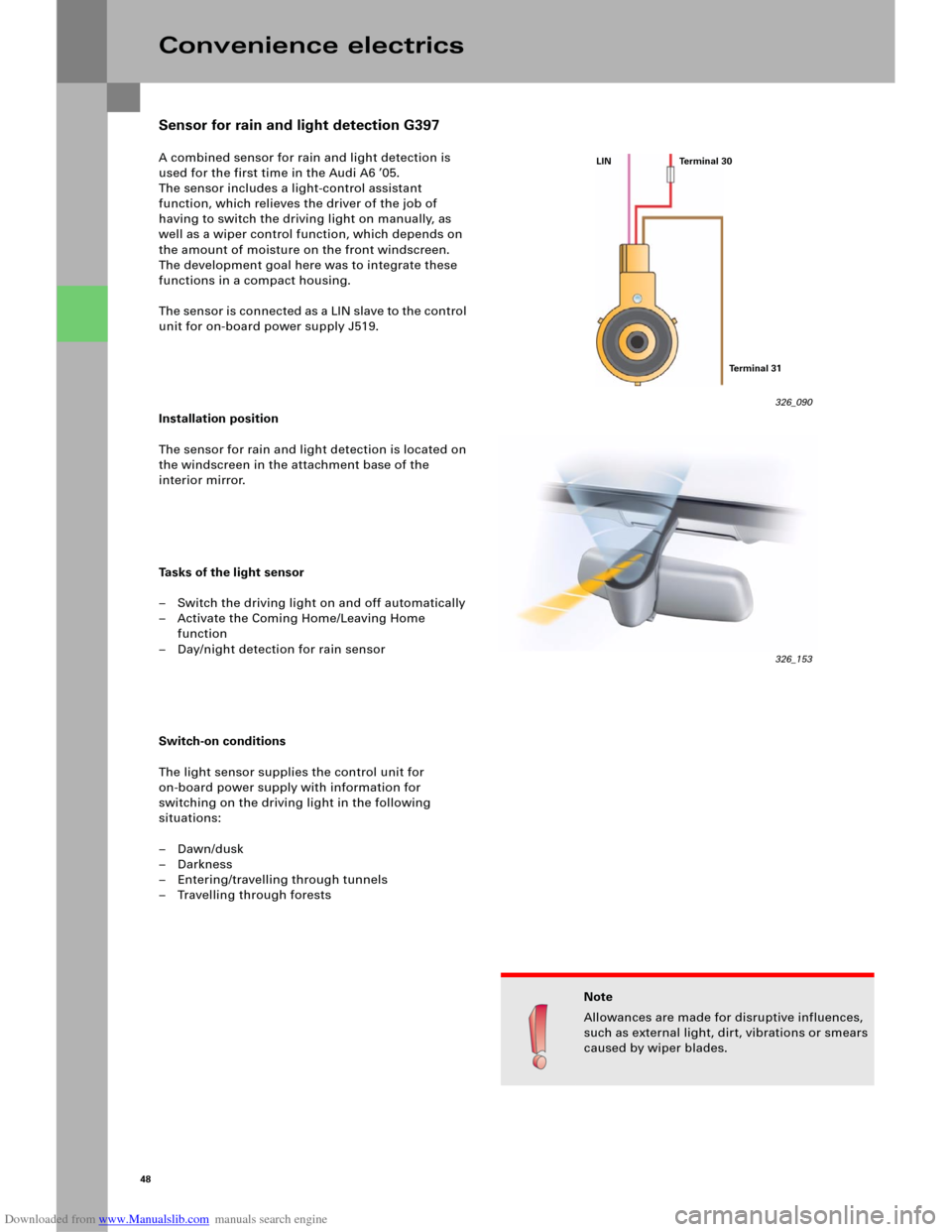
A combined sensor for rain and light detection is
used for the first time in the Audi A6 ’05.
The sensor includes a light-control assistant
function, which relieves the driver of the job of
having to switch the driving light on manually, as
well as a wiper control function, which depends on
the amount of moisture on the front windscreen.
The development goal here was to integrate these
functions in a compact housing.
The sensor is connected as a LIN slave to the control
unit for on-board power supply J519.
Installation position
The sensor for rain and light detection is located on
the windscreen in the attachment base of the
interior mirror.
Tasks of the light sensor
– Switch the driving light on and off automatically
– Activate the Coming Home/Leaving Home
function
– Day/night detection for rain sensor
Switch-on conditions
The light sensor supplies the control unit for
on-board power supply with information for
switching on the driving light in the following
situations:
–Dawn/dusk
–Darkness
– Entering/travelling through tunnels
– Travelling through forests
Convenience electrics
326_090
Note
Allowances are made for disruptive influences,
such as external light, dirt, vibrations or smears
caused by wiper blades.
LIN Terminal 30
Te r m i n a l 3 1
Sensor for rain and light detection G397
326_153
Page 47 of 92

Downloaded from www.Manualslib.com manuals search engine 49
Function of the light sensor
In order to detect certain ambient conditions, such
as tree-lined avenues or routes through tunnels, the
light sensor registers the light intensity in two
areas.
The global field describes the direct brightness on
the vehicle, while the fore-field describes the
lighting conditions in the section of road lying
ahead of the vehicle. This is activated using the
"Auto" setting on the rotary light switch.
Tasks of the rain sensor
The following functions are implemented,
depending on the amount of water on the
windscreen:
– Switch the wiper on and off automatically at
seven different speeds
– Activate the driving light when it is raining
Activation
The rain sensor is activated by positioning the wiper
stalk to the "Intermittent" setting. The driver can
then set four sensitivity ranges using the regulator
for windscreen wiper intermittent operation.
A reference wiper function (wiper action when the
rain/light sensor is activated) is no longer necessary
with this system. This means that the wiper stalk
can always remain at the "Intermittent" setting.
For safety reasons, however, the rain sensor
operation is only activated in this case when a
driving speed of more than 16 km/h is reached, or
when the sensitivity on the regulator for windscreen
wiper intermittent operation is changed.
326_092
326_091
Global field
Fore-field
Note
Manually switched wiper intervals have
priority
Light sensor
Rain sensor
photodiode is
also used
Page 48 of 92

Downloaded from www.Manualslib.com manuals search engine 50
Function of the rain sensor
The rain sensor uses the physical light refraction
principle to register the amount of moisture on the
windscreen. The circular LEDs integrated in the
sensor emit infrared light through the windscreen
from within the interior of the vehicle.
If the windscreen is dry, the infrared light is
reflected on the surface of the glass.
The photodiode integrated in the centre of the
sensor thus records a high light intensity.
If the windscreen is covered with moisture, the
optical properties on the surface of the glass
change. Light now emerges from the windscreen
surface through the light refraction caused by water
drops. As a result, less light is reflected back and the
photodiode records a lower light intensity (light
dispersion principle).
Diagnosis
The control unit for on-board power supply J519 is
used for diagnostic procedures on the sensor for
rain and light detection.
Convenience electrics
326_091 LEDs
Photodiode
326_093Windscreen surface
LED
Photodiode
LED 326_080
Page 49 of 92

Downloaded from www.Manualslib.com manuals search engine 51
The control unit for wiper motor J400 was
redesigned for use in the new Audi A6 ’05. As is
already the case in the Audi A8 ‘03 and Audi A3 ’04,
the control unit and wiper motor are integrated into
one housing.
It is linked to the control unit for on-board power
supply J519 as a LIN-slave control unit.
Functions
– Intermittent
– Intermittent stages (four)
–One-touch wiping
– Wiper function stage 1
– Wiper function stage 2
– Wipe over again 5 seconds after the last
wash-and-wipe action
(at vehicle speed > 5 km/h only)
– Rain sensor function (see Sensor for rain and
light detection G397)
– Service setting
– Alternating parking position (can be coded)
Function diagram
G397 Sensor for rain and light detection
J400 Control unit for wiper motor
J519 Control unit for on-board power supply
Reference
For further information on the control unit
for wiper motor J400, please refer to the
SSP 287, Audi A8 ‘03 – Electrical
Components.
Note
The control unit for on-board power
supply J519 now activates the windscreen
washer pump V5.
326_081
Control unit for wiper motor J400
326_104
Page 50 of 92

Downloaded from www.Manualslib.com manuals search engine 52
An additional on-board power supply control unit is
needed in the Audi A6 ´05 because of the huge
range of functions it offers.
Functions
Control unit 2 for on-board power supply J520
includes the following functions:
– Activate the solenoid valve for Servotronic N119
– Sliding roof convenience opening/closing
– Speed signal for sliding roof
– Tilt sensor for anti-theft warning system
– Glove compartment release
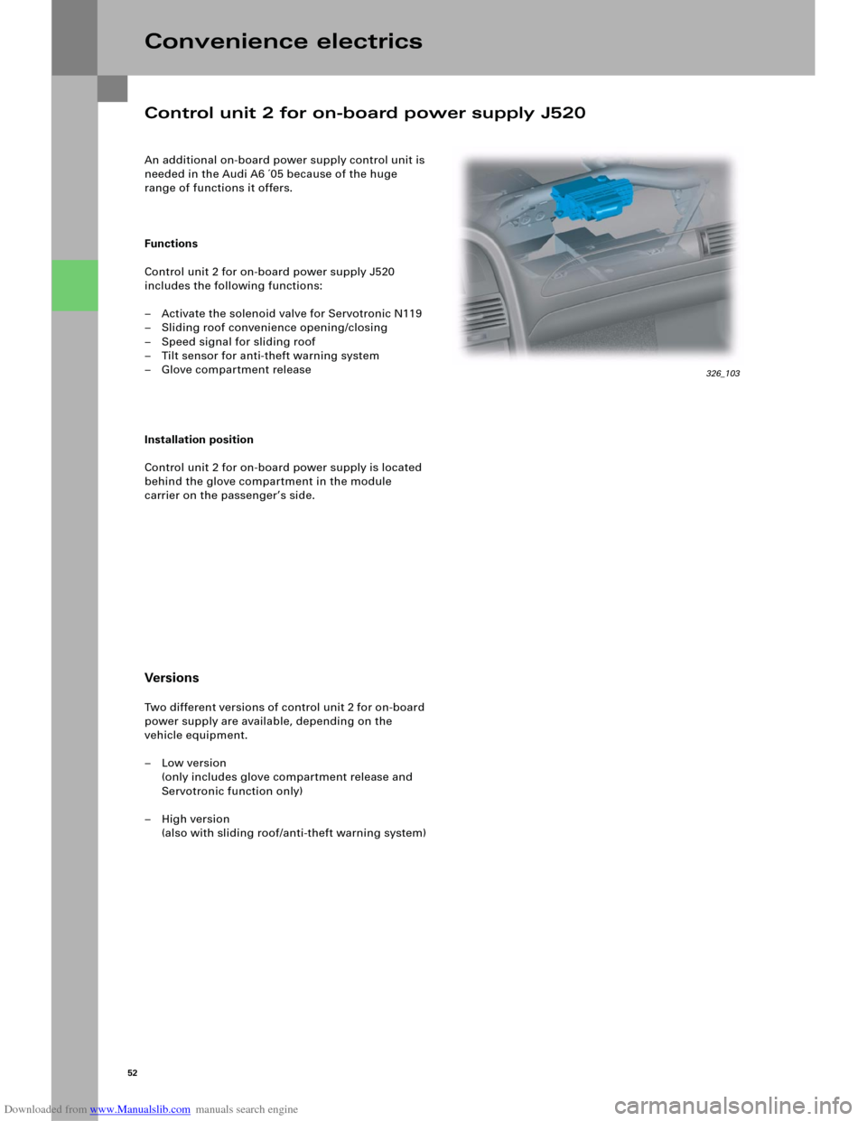
Installation position
Control unit 2 for on-board power supply is located
behind the glove compartment in the module
carrier on the passenger’s side.
Versi on s
Two different versions of control unit 2 for on-board
power supply are available, depending on the
vehicle equipment.
–Low version
(only includes glove compartment release and
Servotronic function only)
–High version
(also with sliding roof/anti-theft warning system)
Convenience electrics
Control unit 2 for on-board power supply J520
326_103