check engine AUDI A6 2005 C5 / 2.G Electrics System Training Manual
[x] Cancel search | Manufacturer: AUDI, Model Year: 2005, Model line: A6, Model: AUDI A6 2005 C5 / 2.GPages: 92, PDF Size: 4.42 MB
Page 19 of 92

Downloaded from www.Manualslib.com manuals search engine 21
The electromechanical steering column lock was
integrated into the control unit for access and start
authorisation.
Functions
– Terminal control:
The control unit for access and start
authorisation puts the information about
terminal 15, 75x, 50, S and P on
CAN Convenience.
The control unit also activates the relays for
terminal 15 and 75x and passes the start request
signal on to the engine control unit.– Locking the steering column:
The motor and gears for locking the steering
column are integrated into the control unit for
access and start authorisation.
The position of the lock is checked using two
integrated micro switches. Terminal 15 is only
switched on after the steering is unlocked fully.
– Immobiliser and component protection:
The control unit is the master for these
functions.
Control unit for access and start authorisation J518
326_095
Page 27 of 92

Downloaded from www.Manualslib.com manuals search engine 29
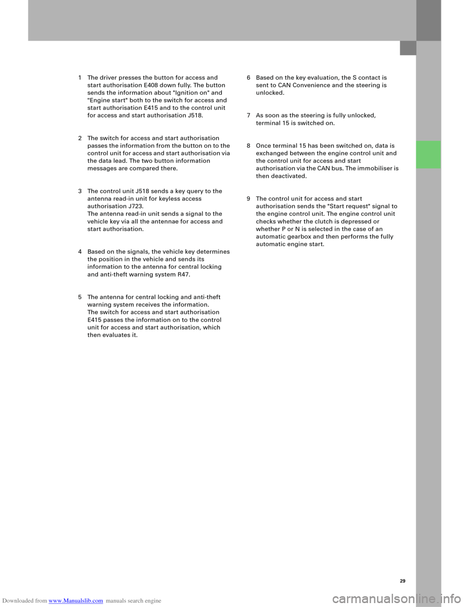
1 The driver presses the button for access and
start authorisation E408 down fully. The button
sends the information about "Ignition on" and
"Engine start" both to the switch for access and
start authorisation E415 and to the control unit
for access and start authorisation J518.
2 The switch for access and start authorisation
passes the information from the button on to the
control unit for access and start authorisation via
the data lead. The two button information
messages are compared there.
3 The control unit J518 sends a key query to the
antenna read-in unit for keyless access
authorisation J723.
The antenna read-in unit sends a signal to the
vehicle key via all the antennae for access and
start authorisation.
4 Based on the signals, the vehicle key determines
the position in the vehicle and sends its
information to the antenna for central locking
and anti-theft warning system R47.
5 The antenna for central locking and anti-theft
warning system receives the information.
The switch for access and start authorisation
E415 passes the information on to the control
unit for access and start authorisation, which
then evaluates it. 6 Based on the key evaluation, the S contact is
sent to CAN Convenience and the steering is
unlocked.
7 As soon as the steering is fully unlocked,
terminal 15 is switched on.
8 Once terminal 15 has been switched on, data is
exchanged between the engine control unit and
the control unit for access and start
authorisation via the CAN bus. The immobiliser is
then deactivated.
9 The control unit for access and start
authorisation sends the "Start request" signal to
the engine control unit. The engine control unit
checks whether the clutch is depressed or
whether P or N is selected in the case of an
automatic gearbox and then performs the fully
automatic engine start.
Page 38 of 92

Downloaded from www.Manualslib.com manuals search engine 40
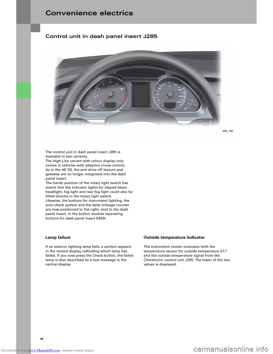
The control unit in dash panel insert J285 is
available in two variants.
The High-Line variant with colour display only
comes in vehicles with adaptive cruise control.
As in the A8 '03, the anti-drive-off feature and
gateway are no longer integrated into the dash
panel insert.
The handy position of the rotary light switch has
meant that the indicator lights for dipped beam
headlight, fog light and rear fog light could also be
fitted directly in the rotary light switch.
Likewise, the buttons for instrument lighting, the
auto-check system and the daily mileage counter
are now positioned to the right, next to the dash
panel insert, in the button module (operating
buttons for dash panel insert E493).
Convenience electrics
Lamp failure
If an exterior lighting lamp fails, a symbol appears
in the central display indicating which lamp has
failed. If you now press the Check button, the failed
lamp is also described by a text message in the
central display.
Outside temperature indicator
The instrument cluster evaluates both the
temperature sensor for outside temperature G17
and the outside temperature signal from the
Climatronic control unit J255. The lower of the two
values is displayed.
Control unit in dash panel insert J285
326_145
Page 45 of 92

Downloaded from www.Manualslib.com manuals search engine 47
Diagnosis
Basic settings
After the control unit for on-board power
supply J519 or the steering column or the switch for
steering column adjustment E167 is replaced, a
basic setting in axial and vertical position must be
implemented for the steering column.
Actuator test
An actuator test can be used to carry out the
following checks:
– Indicator light for hazard warning lights K6
– Lamp for parking light, left M1
– Lamp for parking light, right M3
– Lamp for dipped beam headlight, left M29
– Lamp for dipped beam headlight, right M31
– Lamp for high beam headlight, left M30
– Lamp for high beam headlight, right M32
– Lamp for left fog light L22
– Lamp for right fog light L23
– Lamp for daytime driving light, left L174
– Lamp for daytime driving light, right L175
– Direction indicator lights, left
– Direction indicator lights, right
– Footwell light, left W9
– Footwell light, right W10
– Wiper, top turning position
– Wiper, bottom turning position
– Windscreen washer pump V5
– Relay for dual-pitch horn
–Terminal 58
Coding
The control unit for on-board power supply J519 can
be coded for the functions
–Daytime driving light,
– Driving light assistant,
– Headlight type,
– Footwell lighting and
–Country versions
using the diagnosis tester.
Note
The actuator test can be performed either
sequentially (in sequence) or selectively
(individual selection).
Page 52 of 92

Downloaded from www.Manualslib.com manuals search engine 54
The tilt sensor for the anti-theft warning system is
integrated directly in control unit 2 for on-board
power supply J520 in the new Audi A6 ‘05.
The fluid-filled sensor registers changes in the
vehicle tilt both transversely and longitudinally,
thereby preventing incorrect triggering as a result of
shaking through viscous fluid and electronic delay.
The current tilt values can be read out using
measured-value blocks.
Diagnosis
– Measured-value blocks
Measured-value blocks are available for the
following functions:
– Servotronic
– Sliding roof
– Tilt angle
–Actuator test
Checks can be carried out for the following
functions, depending on the version:
– Glove compartment release
– Servotronic valve
– Sliding roof activation (can be measured
using a multimeter on the on-board power
supply control unit, sliding roof does not
open, however, if it is not released by the
central control unit for the convenience
system)
–Coding
The High-Line version of control unit 2 for
on-board power supply J520 must be coded for
the following functions:
– Tilt sensor (with or without)
– Sliding roof (with or without)
Convenience electrics
Note
The tilt sensor function can be switched off
using a button in the driver’s door panel.
Reference
For further information on the tilt sensor
function, please refer to the SSP 254,
Audi A4 ‘01 – Technology.
Tilt sensor for anti-theft warning system
Page 58 of 92

Downloaded from www.Manualslib.com manuals search engine 60
Diagnosis
The central control unit for convenience
system, J393, has the usual diagnostic functions,
such as read fault memory, read measured value
blocks, adaptation, coding, as well as selective and
sequential actuator test at its disposal.
Actuator test
The selective actuator test initiated by the diagnosis
tester can be used to check the following actuators:
– Indicator light for safe central locking K133
(in door rim)
– Lock central locking signal (once)
– Activate safe locking for doors (once)
– Unlock central locking signal
– Lock filler flap
– Unlock filler flap
– Lamp for left brake light M9
– Lamp for right brake light M10
– Lamp for high-level brake light M25
– Lamps for tail light, left
– Lamp for parking light, left M43
– Lamps for tail light, right
– Lamp for parking light, right M44
– Lamp for reversing light, left M16
– Lamp for reversing light, right M17
– Lamp for direction indicator light, rear left M6
– Lamp for direction indicator light, rear right M8
– Lamp for rear fog light, left L46
– Lamp for rear fog light, right L47
Coding
This diagnostic option can be used to perform
coding, for example, for these functions:
– Anti-theft warning system
– Central locking (normal/selective)
–Tilt sensor
– Passenger compartment sensor
– Convenience function via radio
–Right-hand traffic
–Avant detection
–Rear sun blind
Convenience electrics
Note
In addition to the selective actuator test,
the diagnosis software also includes the option
of a sequential actuator test.
– Number plate light X
– Boot light W3
– Footwell light, rear left W45
– Footwell light, rear right W46
– Activation of rear lid remote unlocking
(rotary latch opens, closing aid moves up)
– Motor for rear sun blind (rear sun blind moves in
both directions)
– Signal for rear window heater activation
–Interior lighting
– Acknowledgement of anti-theft warning system
horn
–RoW/USA
–Light package
– Tank cap lock detection
– Equipment (Basic/High-Line)
–Sliding roof
– Multi-function control unit (taxi/emergency
doctor/fire brigade, installed/not installed)
Page 87 of 92

Downloaded from www.Manualslib.com manuals search engine 89
Mobile baseplate diagnosis
The mobile baseplate is diagnosed as standard
using the address word 77 in the VAS tester.
A selective or sequential actuator test can be
performed to check the output of the audio signal to
the relevant sound system, radio mute operation,
and whether or not a switched-on phone was
detected.
Measured-value blocks
Measured-value blockDesignation
01General: Battery positive voltage
02MOST: MOST address, FOT temperature
03Status of ring break diagnosis line
05Input signals: PTT, Mobile inserted, Mobile switched on, Communication active
10Reception field strength of the mobile phone
11Status of external antenna for mobile baseplate
14Currently connected Bluetooth devices
19Microphone: Microphone voltage, microphone power consumption
20Number of bonded (known) Bluetooth devices
48Cut-off level of control unit for power management J644
80Control unit identification: Manufacturer codes
81Control unit identification: Serial number
130Status of Bluetooth antenna