gearbox AUDI A6 2005 C5 / 2.G Electrics System Training Manual
[x] Cancel search | Manufacturer: AUDI, Model Year: 2005, Model line: A6, Model: AUDI A6 2005 C5 / 2.GPages: 92, PDF Size: 4.42 MB
Page 12 of 92

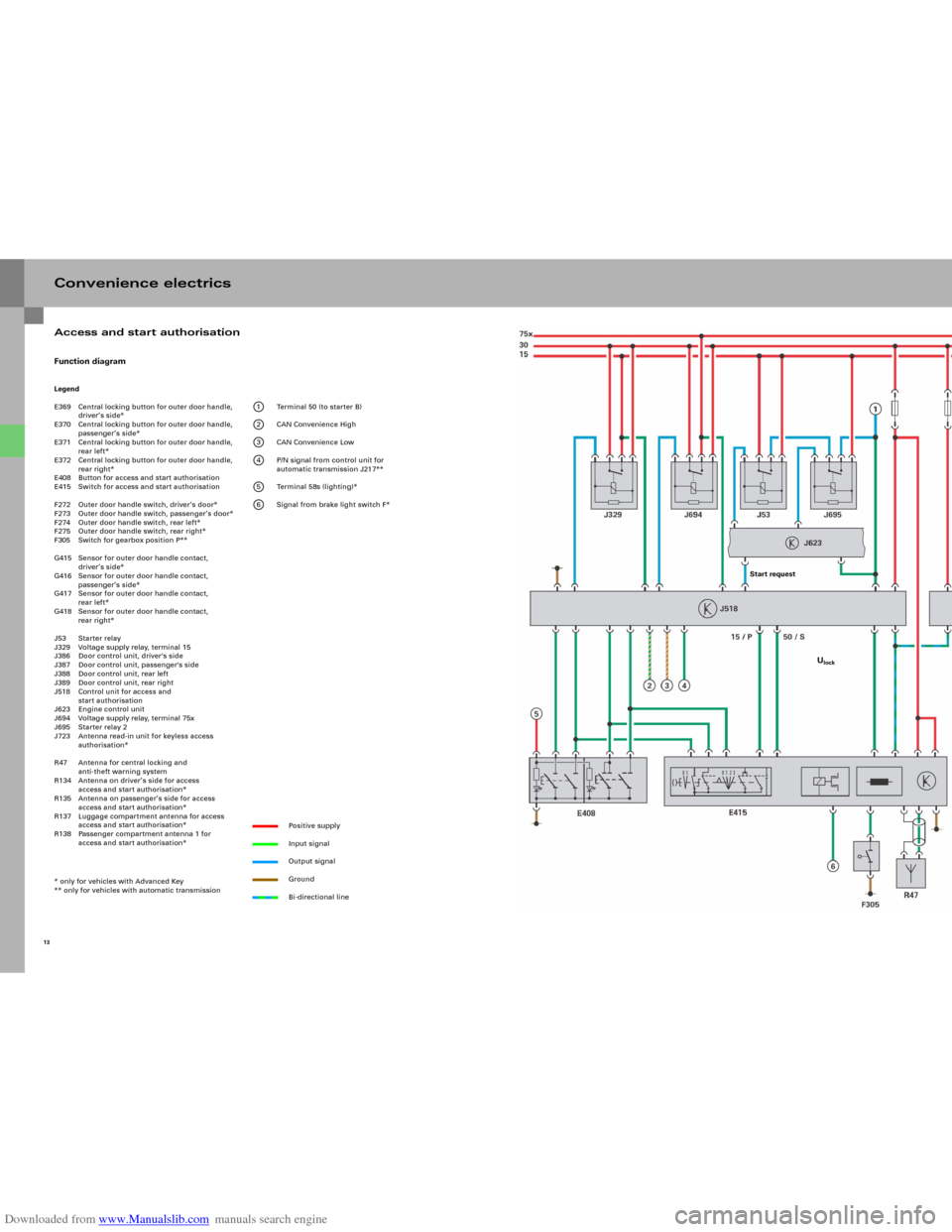
Downloaded from www.Manualslib.com manuals search engine Convenience electricsFunction diagramLegend
E369 Central locking button for outer door handle,
driver’s side*
E370 Central locking button for outer door handle,
passenger’s side*
E371 Central locking button for outer door handle,
rear left*
E372 Central locking button for outer door handle,
rear right*
E408 Button for access and start authorisation
E415 Switch for access and start authorisation
F272 Outer door handle switch, driver’s door*
F273 Outer door handle switch, passenger’s door*
F274 Outer door handle switch, rear left*
F275 Outer door handle switch, rear right*
F305 Switch for gearbox position P**
G415 Sensor for outer door handle contact,
driver’s side*
G416 Sensor for outer door handle contact,
passenger’s side*
G417 Sensor for outer door handle contact,
rear left*
G418 Sensor for outer door handle contact,
rear right*
J53 Starter relay
J329 Voltage supply relay, terminal 15
J386 Door control unit, driver's side
J387 Door control unit, passenger's side
J388 Door control unit, rear left
J389 Door control unit, rear right
J518 Control unit for access and
start authorisation
J623 Engine control unit
J694 Voltage supply relay, terminal 75x
J695 Starter relay 2
J723 Antenna read-in unit for keyless access
authorisation*
R47 Antenna for central locking and
anti-theft warning system
R134 Antenna on driver’s side for access
access and start authorisation*
R135 Antenna on passenger’s side for access
access and start authorisation*
R137 Luggage compartment antenna for access
access and start authorisation*
R138 Passenger compartment antenna 1 for
access and start authorisation*
* only for vehicles with Advanced Key
** only for vehicles with automatic transmission
1 Terminal 50 (to starter B)
2 CAN Convenience High
3 CAN Convenience Low
4 P/N signal from control unit for
automatic transmission J217**
5 Terminal 58s (lighting)*
6 Signal from brake light switch F*
Positive supply
Input signal
Output signal
Ground
Bi-directional line
13
Access and start authorisation
Start request
Ulock
Page 18 of 92

Downloaded from www.Manualslib.com manuals search engine 20
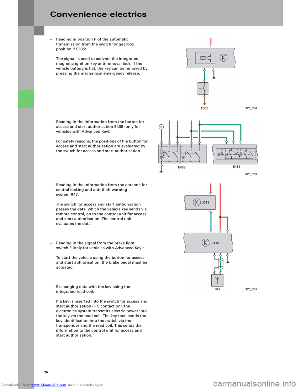
– Reading in position P of the automatic
transmission from the switch for gearbox
position P F305:
The signal is used to activate the integrated,
magnetic ignition key anti-removal lock. If the
vehicle battery is flat, the key can be removed by
pressing the mechanical emergency release.
– Reading in the information from the button for
access and start authorisation E408 (only for
vehicles with Advanced Key):
Fo r s a fe t y r e as o n s , t h e p o s i t i o n s o f t h e b u t to n fo r
access and start authorisation are evaluated by
the switch for access and start authorisation.
–
– Reading in the information from the antenna for
central locking and anti-theft warning
system R47:
The switch for access and start authorisation
passes the data, which the vehicle key sends via
remote control, on to the control unit for access
and start authorisation. The control unit
evaluates the data.
– Reading in the signal from the brake light
switch F (only for vehicles with Advanced Key):
To start the vehicle using the button for access
and start authorisation, the brake pedal must be
actuated.
– Exchanging data with the key using the
integrated read coil:
If a key is inserted into the switch for access and
start authorisation (= S contact on), the
electronics system transmits electric power into
the key via the read coil. The key then sends the
key identification into the switch via the
transponder and the read coil. This sends the
information to the control unit for access and
start authorisation.
Convenience electrics
326_069 326_068
326_065
Page 27 of 92

Downloaded from www.Manualslib.com manuals search engine 29
1 The driver presses the button for access and
start authorisation E408 down fully. The button
sends the information about "Ignition on" and
"Engine start" both to the switch for access and
start authorisation E415 and to the control unit
for access and start authorisation J518.
2 The switch for access and start authorisation
passes the information from the button on to the
control unit for access and start authorisation via
the data lead. The two button information
messages are compared there.
3 The control unit J518 sends a key query to the
antenna read-in unit for keyless access
authorisation J723.
The antenna read-in unit sends a signal to the
vehicle key via all the antennae for access and
start authorisation.
4 Based on the signals, the vehicle key determines
the position in the vehicle and sends its
information to the antenna for central locking
and anti-theft warning system R47.
5 The antenna for central locking and anti-theft
warning system receives the information.
The switch for access and start authorisation
E415 passes the information on to the control
unit for access and start authorisation, which
then evaluates it. 6 Based on the key evaluation, the S contact is
sent to CAN Convenience and the steering is
unlocked.
7 As soon as the steering is fully unlocked,
terminal 15 is switched on.
8 Once terminal 15 has been switched on, data is
exchanged between the engine control unit and
the control unit for access and start
authorisation via the CAN bus. The immobiliser is
then deactivated.
9 The control unit for access and start
authorisation sends the "Start request" signal to
the engine control unit. The engine control unit
checks whether the clutch is depressed or
whether P or N is selected in the case of an
automatic gearbox and then performs the fully
automatic engine start.
Page 60 of 92

Downloaded from www.Manualslib.com manuals search engine 62
326_119
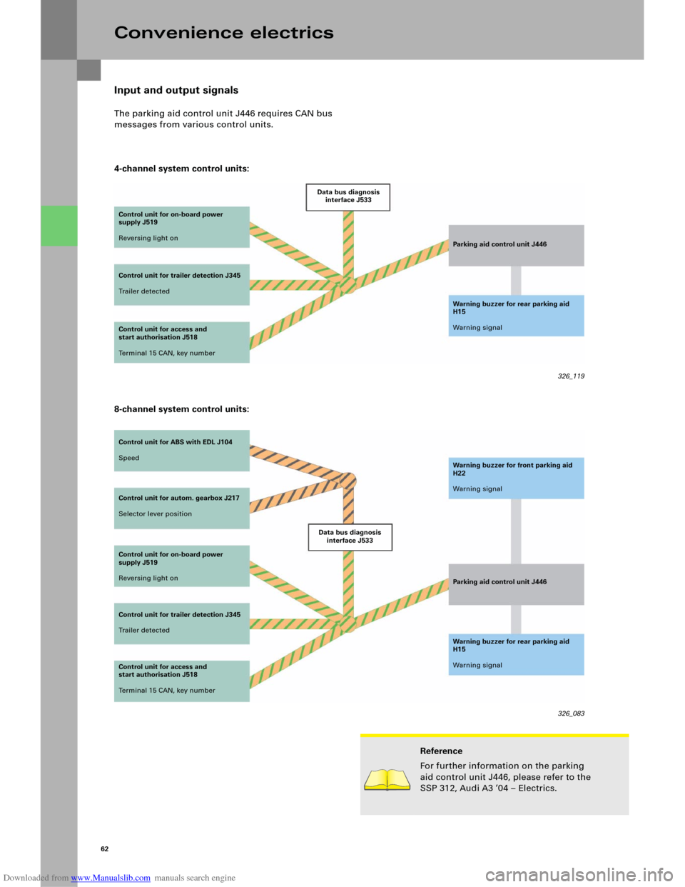
Input and output signals
The parking aid control unit J446 requires CAN bus
messages from various control units.
4-channel system control units:
Convenience electrics
Control unit for on-board power
supply J519
Reversing light on
Control unit for trailer detection J345
Tr a i l e r d e t e c t e dData bus diagnosis
interface J533
Parking aid control unit J446
Warning buzzer for rear parking aid
H15
Warning signal
Control unit for access and
start authorisation J518
Terminal 15 CAN, key number
Control unit for ABS with EDL J104
Speed
Control unit for autom. gearbox J217
Selector lever position
Control unit for on-board power
supply J519
Reversing light on
Control unit for trailer detection J345
Tr a i l e r d e t e c t e dData bus diagnosis
interface J533Warning buzzer for front parking aid
H22
Warning signal
Parking aid control unit J446
Warning buzzer for rear parking aid
H15
Warning signal
326_083 Control unit for access and
start authorisation J518
Terminal 15 CAN, key number
Reference
For further information on the parking
aid control unit J446, please refer to the
SSP 312, Audi A3 ’04 – Electrics.
8-channel system control units:
Page 91 of 92

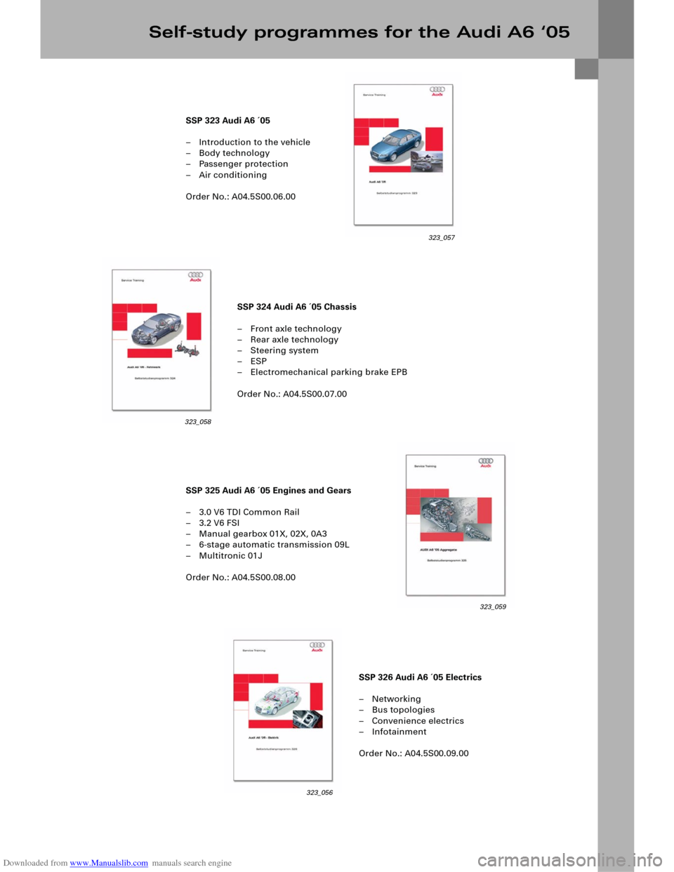
Downloaded from www.Manualslib.com manuals search engine SSP 324 Audi A6 ´05 Chassis
– Front axle technology
– Rear axle technology
– Steering system
–ESP
– Electromechanical parking brake EPB
Order No.: A04.5S00.07.00
SSP 326 Audi A6 ´05 Electrics
–Networking
– Bus topologies
– Convenience electrics
– Infotainment
Order No.: A04.5S00.09.00 SSP 323 Audi A6 ´05
– Introduction to the vehicle
–Body technology
– Passenger protection
– Air conditioning
Order No.: A04.5S00.06.00
SSP 325 Audi A6 ´05 Engines and Gears
– 3.0 V6 TDI Common Rail
–3.2 V6 FSI
– Manual gearbox 01X, 02X, 0A3
– 6-stage automatic transmission 09L
– Multitronic 01J
Order No.: A04.5S00.08.00
Self-study programmes for the Audi A6 ‘05
323_057
323_058
323_059
323_056