wheel AUDI A6 2005 C5 / 2.G Electrics System Training Manual
[x] Cancel search | Manufacturer: AUDI, Model Year: 2005, Model line: A6, Model: AUDI A6 2005 C5 / 2.GPages: 92, PDF Size: 4.42 MB
Page 4 of 92

Downloaded from www.Manualslib.com manuals search engine 4
Overview
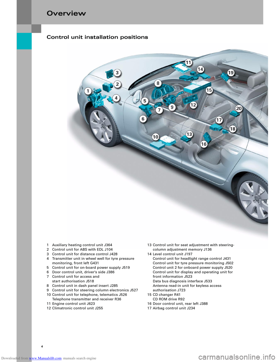
1 Auxiliary heating control unit J364
2 Control unit for ABS with EDL J104
3 Control unit for distance control J428
4 Transmitter unit in wheel well for tyre pressure
monitoring, front left G431
5 Control unit for on-board power supply J519
6 Door control unit, driver's side J386
7 Control unit for access and
start authorisation J518
8 Control unit in dash panel insert J285
9 Control unit for steering column electronics J527
10 Control unit for telephone, telematics J526
Telephone transmitter and receiver R36
11 Engine control unit J623
12 Climatronic control unit J25513 Control unit for seat adjustment with steering-
column adjustment memory J136
14 Level control unit J197
Control unit for headlight range control J431
Control unit for tyre pressure monitoring J502
Control unit 2 for onboard power supply J520
Control unit for display and operating unit for
front information J523
Data bus diagnosis interface J533
Antenna read-in unit for keyless access
authorisation J723
15 CD changer R41
CD ROM drive R92
16 Door control unit, rear left J388
17 Airbag control unit J234
Control unit installation positions
Page 5 of 92

Downloaded from www.Manualslib.com manuals search engine 5
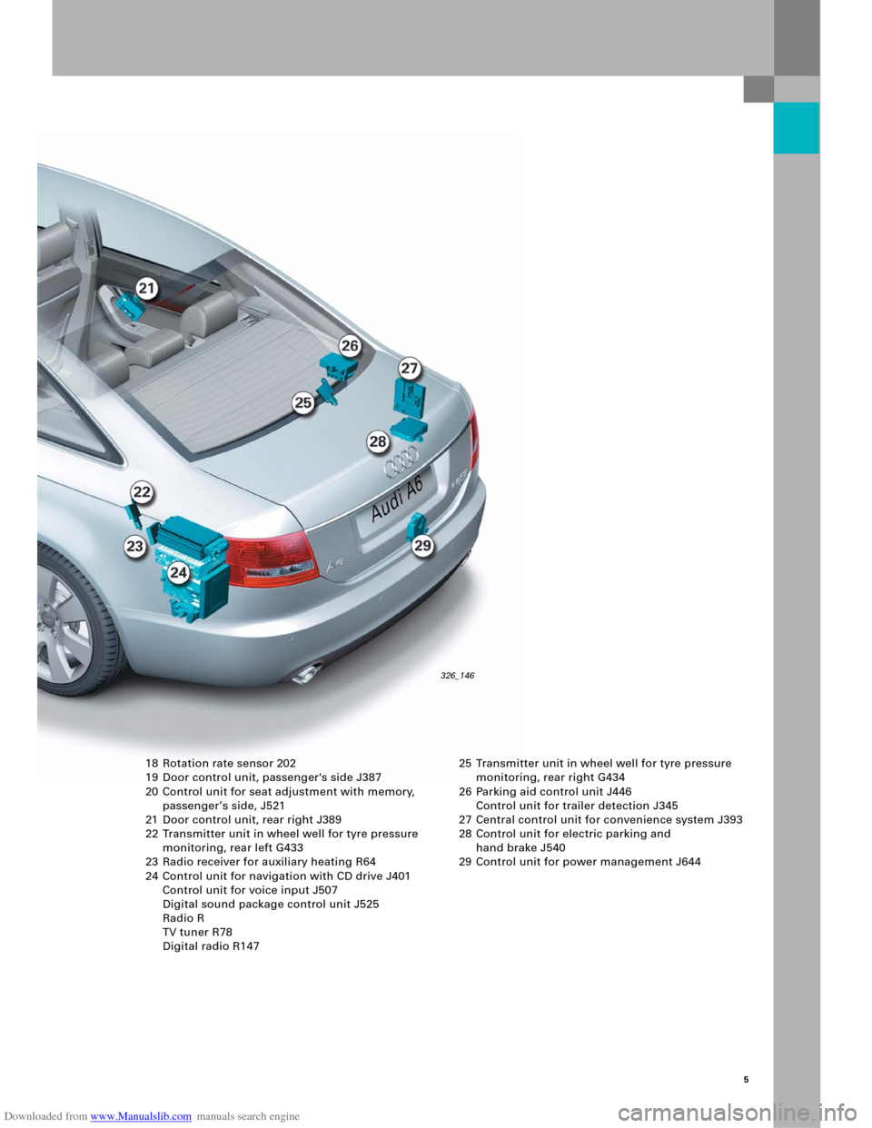
18 Rotation rate sensor 202
19 Door control unit, passenger's side J387
20 Control unit for seat adjustment with memory,
passenger’s side, J521
21 Door control unit, rear right J389
22 Transmitter unit in wheel well for tyre pressure
monitoring, rear left G433
23 Radio receiver for auxiliary heating R64
24 Control unit for navigation with CD drive J401
Control unit for voice input J507
Digital sound package control unit J525
Radio R
TV tuner R78
Digital radio R147 25 Transmitter unit in wheel well for tyre pressure
monitoring, rear right G434
26 Parking aid control unit J446
Control unit for trailer detection J345
27 Central control unit for convenience system J393
28 Control unit for electric parking and
hand brake J540
29 Control unit for power management J644
326_146
Page 6 of 92

Downloaded from www.Manualslib.com manuals search engine 6
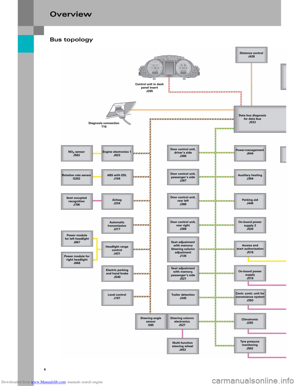
Bus topology
Overview
NOX sensor
J583
Rotation rate sensor
G202
Seat occupied
recognition
J706
Power module
for left headlight
J667
Power m odule for
right headlight
J668
Level control
J197 Electric parking
and hand brake
J540 Headlight range
control
J431 Automatic
transmission
J217 Airbag
J234 ABS with EDL
J104 Engine electronics 1
J623 Diagnosis connection
T16Control unit in dash
panel insert
J285Distance control
J428
Data bus diagnosis
for data bus
J533
Door control unit,
driver’s side
J386
Door control unit,
passenger’s side
J387
Door control unit,
rear left
J388
Door control unit,
rear right
J389
Seat adjustment
with memory
Steering column
adjustment
J136
Seat adjustment
with memory,
passenger’s side
J521
Trailer detection
J345
Steering column
electronics
J527
Multi-function
steering wheel
J453 Steering-angle
sensor
G85Power management
J644
Auxiliary heating
J364
Parking aid
J446
On-board power
supply 2
J520
Access and
start authorisation
J518
On-board power
supply
J519
Centr. contr. unit for
convenience system
J393
Climatronic
J255
Tyre pressure
monitoring
J502
Page 32 of 92

Downloaded from www.Manualslib.com manuals search engine 34
Adaptive light
The adaptive light works as a dynamic corner-
sensitive headlight. With the dynamic cornering
headlight, the headlight projection module is
pivoted horizontally by an integrated motor.
The headlight lenses and the bracket do not turn.
The pivot angle is approx. 15° on the inner curve
side and 7.5° on the outer curve side.
The various pivot angles have advantages in that
they provide better lighting for corner routes.
In this case, the inner-curve module pivots in twice
as much as the outer-curve module.
This achieves the maximum possible illumination
width with homogeneous light distribution.
No pivoting when vehicle is stationary
The projection modules are not pivoted at driving
speeds of < 6 km/h.
The pivot angle essentially depends on the steering
wheel angle at speeds of more than 10 km/h.
This complies with the legal requirement that the
headlights must not be pivoted when the vehicle is
stationary. At the same time, a slight transition to
headlight pivoting occurs during acceleration from
idle when the steering lock remains constant.
Convenience electrics
326_077
Pivot range
326_076
Page 33 of 92

Downloaded from www.Manualslib.com manuals search engine 35
Internal structure
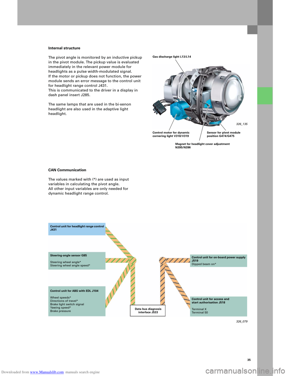
The pivot angle is monitored by an inductive pickup
in the pivot module. The pickup value is evaluated
immediately in the relevant power module for
headlights as a pulse width-modulated signal.
If the motor or pickup does not function, the power
module sends an error message to the control unit
for headlight range control J431.
This is communicated to the driver in a display in
dash panel insert J285.
The same lamps that are used in the bi-xenon
headlight are also used in the adaptive light
headlight.
CAN Communication
The values marked with (*) are used as input
variables in calculating the pivot angle.
All other input variables are only needed for
dynamic headlight range control.
326_079 Data bus diagnosis
interface J533 Co n t ro l u n it fo r h e a d li g h t ra n g e c o n t ro l
J431
Steering-angle sensor G85
Steering wheel angle*
Steering wheel angle speed*
Control unit for ABS with EDL J104
Wheel speeds*
Directions of travel*
Brake light switch signal
Yawing speed*
Brake pressureControl unit for on-board power supply
J519
Dipped beam on*
Control unit for access and
start authorisation J518
Te r m i n a l X
Te r m i n a l 5 0
Gas discharge light L13/L14
326_135
Control motor for dynamic
cornering light V318/V319
Magnet for headlight cover adjustment
N395/N396Sensor for pivot module
position G474/G475
Page 34 of 92

Downloaded from www.Manualslib.com manuals search engine 36
Signal and data exchange
The same sensors that are used for dynamic
headlight range control for bi-xenon headlights are
also used as level sensors. They send a pulse
width-modulated signal to the control unit for
headlight range control. Data is exchanged between
t h e c o n t ro l u n i t fo r h e ad l i gh t ra n g e c o n tro l J 4 3 1 an d
the power modules in the headlight on the left J667
and right J668 via a 500-kBaud CAN.
Show Room function
The Show Room function can be used to pivot the
headlights by moving the steering wheel – even
when the vehicle is stationary – for presentation.
The function can be adapted using the diagnosis
tester in the control unit for headlight beam
adjustment.
If the vehicle is then driven at more than 30 km/h,
the function is permanently disabled. The function
can be switched on again at any time using the
diagnosis tester.
Convenience electrics
326_074
Audi
Audi A6 2005>
2005 (5)
Saloon
BBJ 3.0l Motronic / 160 kW Guided fault-finding
Function/component selection
Selecting a function or component
Body (Rep. Gr. 01; 50 - 97)
Electrical system (Rep. Gr. 01; 27, 90 - 97)
01 – Self-diagnosis systems
55 – Dynamic headlight range control
J431 – Dynamic headlight range control, Functions
J431 – Contr. unit, head. range control (HRC), General system descr.
J431 – Control unit for headlight range control (HRC), Adaptation
J431 – Contr. unit, head. range control (HRC), Adapt. – Show Room
J431 – Control unit for headlight range control (HRC), Coding
J431 – Control unit for headlight range control (HRC), Replacing
J431 – Control unit for headlight range control (HRC), Basic setting
J431 – Contr. unit, head. range contr. (HRC), Read. meas.-val. blocks
J431 - Contr. unit, head. range control (HRC), selective actuator test
J431 – Contr. unit, head. range contr. (HRC), sequential actuator test
326_085
Page 59 of 92

Downloaded from www.Manualslib.com manuals search engine 61
You may already be familiar with the acoustic
parking aid function "APS" from the Audi A3 ´04.
For use in the Audi A6 ´05, a 4-channel system with
sensors on the rear bumper and an 8-channel
system with sensors on the front and rear bumpers
are available.
Ve rs i on s
The parking aid control unit will be available as
4-channel system and 8-channel system versions.
Only the 4-channel version is available on the
Audi A6 ’05 for the US market.
Installation position
The parking aid control unit is installed above the
right wheel housing in the boot. It is secured in a
frame under the control unit for trailer detection.
Function
The area around the vehicle is monitored by four
ultrasound converters integrated into the front
bumper (8-channel system only) and four
ultrasound converters integrated into the rear
bumper. The acoustic message comes from a tone
generator in the front area of the vehicle and a tone
generator in the back area of the vehicle (only at the
back for the 4-channel system). A parking aid switch
can be used to activate or deactivate the parking aid
manually (8-channel system only). The MMI allows
the customer to adjust the volume and frequency of
the acoustic output of the parking aid.
If the control unit for trailer detection reports the
presence of a trailer on the vehicle via the CAN bus,
the four sensors in the rear bumper are switched
off. The front area of the vehicle is still monitored,
however.
326_100
Parking aid control unit J446
326_101
Page 66 of 92

Downloaded from www.Manualslib.com manuals search engine 68
Multimedia Interface (MMI)
Equipment versions
As in the current Audi A8 ’03, the MMI operating
concept is now also integrated as standard in the
new Audi A6 ’05. Data is transferred between the
individual Infotainment control units via MOST bus
technology and the process is technically identical
to the Infotainment system in the current
Audi A8 ‘03. Driver-relevant functions, such as
on-board computer or navigation, are displayed in
the centre display of dash panel insert J285.
Selected functions for the telephone, radio and
CD control and volume control can be operated
using the multi-function steering wheel.Unlike the current Audi A8 ‘03, several versions of
the control unit for the front display unit J523, the
master control unit in the optical Infotainment bus,
are installed in the Audi A6 ´05, depending on the
optional equipment selected.
The Basic, Basic Plus and Basic Navigation versions
have the same hardware platform, which is
expanded to include the required optional extras.
The MMI High version, on the other hand, uses the
same hardware as the current Audi A8 ‘03.
Furthermore, the data bus diagnosis interface J533,
which assures communication with the other
networked components in the vehicle, is connected
to the MOST bus.
Infotainment
Note
Information on the MOST bus can be found in
the SSP 286 – New data bus systems,
LIN, MOST, Bluetooth.Reference
For information on the Infotainment system
with optical data transfer, please refer to the
SSP 293, Audi A8 ’03 – Infotainment.
326_143 Display elements in the optimum field of vision
Separation of display and operation
– optimum readability
– optimum ease of operation
Operating elements within primary reach
Page 67 of 92

Downloaded from www.Manualslib.com manuals search engine 69
MMI Basic
Standard equipment in the new Audi A6 includes
MMI Basic with the MMI operating concept, a
7" monochrome display (J685) in the dash panel
inser t as well as an integrated, analogue radio tuner
and 4x antenna diversity, CD drive and a 2x20-watt
amplifier.
In principle, these drivers are available in all
versions of the control unit for front
information J523.
In the MMI Basic version, the loudspeakers that are
integrated into the front doors are connected
directly to the control unit for front
information J523.
If the Standard Sound System or BOSE option is
installed, this internal amplifier is deactivated via
coding. The loudspeakers are then connected to the
relevant digital sound package control unit J525.Digital tuner technology will be available in the
Audi A6 at a later date. Depending on the market in
question, a satellite radio receiver or a receiver for
terrestrially emitted, but digitally coded
transmissions will then be available.
Legend
The orange symbols represent the possible optional
equipment. If a relevant option is missing, simply
follow the route indicated by arrows to close the
MOST ring.
326_042 Front information
are used
in the tester
J685Multimedia
operating unit
E380Antenna booster
R24Loudspeaker
front
Control unit for front information J523
+ Radio R
+ CD player R89
+ Amplifier R12 (active)Loudspeaker
DSP amplifier
J525
DSP amplifier
BOSE
J525
Loudspeaker
CD changer
R41 Te l e p h o n e
transmitter and
for telephone
R36 Data bus diagnosis
interface
J533Antenna
amplifier 2
R111
Steering column
electronics
J527Multi-function
steering wheel
J453
Page 68 of 92

Downloaded from www.Manualslib.com manuals search engine 70
MMI Basic Plus
As an option, the MMI Basic system can be
equipped with additional functions in the radio and
sound field in the form of a "Plus" version.
This includes, for example, a TP Memo function,
which enables the recording of traffic
announcements for a duration of eight minutes in
total.
A programmable recording period can be used to
provide up-to-date traffic announcements before
starting a journey. Stored traffic messages are
automatically deleted after six hours to ensure that
they are always up-to -date. Instead of the integrated
amplifier, the standard sound system with its own
digital sound package control unit J525 will be used
as standard as of this MMI version.
The internal amplifier can be deactivated via coding
in this and later MMI versions.
Infotainment
Legend
The orange symbols represent the possible optional
equipment. If a relevant option is missing, simply
follow the route indicated by arrows to close the
MOST ring.
326_043 Front information
are used
in the tester
J685Multimedia
operating unit
E380Antenna booster
R24
Control unit for front information J523
+ Radio R
+ CD player R89Loudspeaker
DSP amplifier
J525
DSP amplifier
BOSE
J525
Loudspeaker
Te l e p h o n e
transmitter and
for telephone
R36 Data bus diagnosis
interface
J533CD changer
R41 Antenna
amplifier 2
R111
Reference
Please refer to the Driver’s Manual for
information on operating the enhanced TP
Memo function!
Steering column
electronics
J527Multi-function
steering wheel
J453