lane assist AUDI A6 2011 Owners Manual
[x] Cancel search | Manufacturer: AUDI, Model Year: 2011, Model line: A6, Model: AUDI A6 2011Pages: 370, PDF Size: 87.15 MB
Page 4 of 370
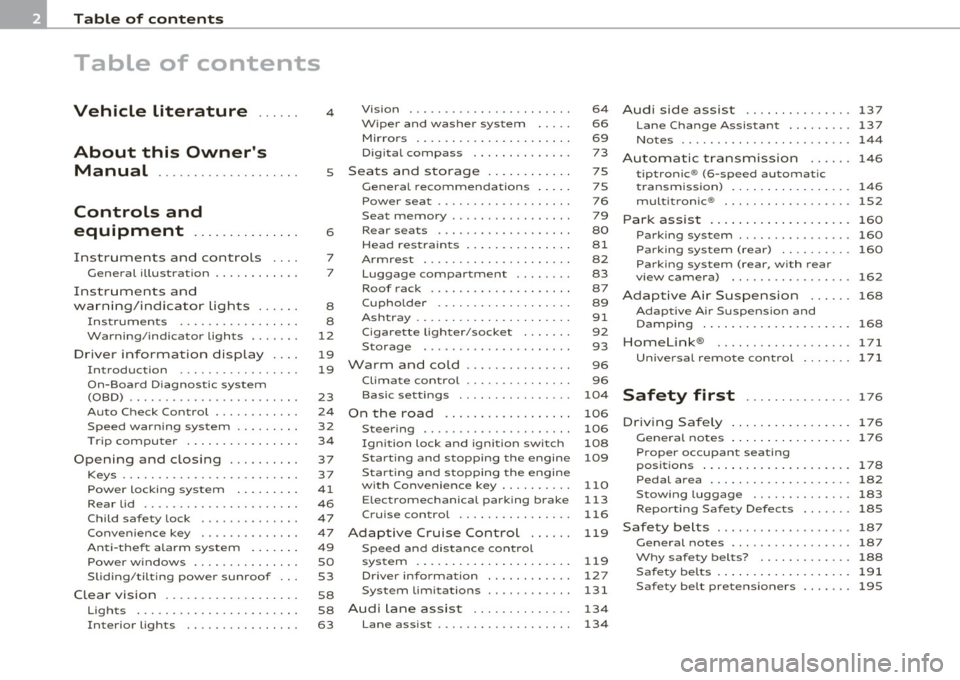
Table of contents
Table of contents
Vehicle literature ..... .
About this Owner's Manual .......... ....... .. .
Controls and
equipment .............. .
Instruments and controls ... .
General illustration ........... .
Instruments and
warning/indicator Lights ..... . Instruments ... ... .......... .
Warning/indicator ligh ts ..... . .
Driver information display ... .
Introduction ...... ......... . .
On-Board Diagno stic sy ste m
(OBD) . ..... ....... .......... .
Auto Ch eck Control ........... .
Speed warning system ........ .
Tr ip computer ............ ... .
Opening and closing ......... . Keys ............ ............ .
Power locking system
Rear lid .... ..... ............ .
Child safety Lock ............. .
Convenience key ............. .
Anti-theft alarm sys tem ...... .
Power windows .............. .
Sliding/tilting power sunroof .. .
Clear vision .. .... ............ .
L ights ... .. ........ ......... .
Interior ligh ts ... ... .. ....... .
4
5
6
7
7
8
8
12
19
19
23
24
32
34
37
3 7
41
46
47
47
49
so
53
58
58
63 Vi
sion .................... .. .
Wiper and washer system Mirrors ... ............... ... .
Digital compass ............ .
Seats and storage ........ ... .
General recommendations .... .
Power seat . ................. .
S eat m emory ............... . .
Rear sea ts ... ... .. .......... .
Head res train ts ........... ... .
Armrest .. .. ................ .
Luggage compar tm en t ..... .. .
Roof ra ck . .... .... .......... .
Cupholder .................. .
Ashtray .. ................... .
Cigarette Lighter/socket ...... .
S torag e ................ .. .. .
Warm and cold .... .......... .
Cl imate control ........ .. .... .
Ba sic se tt ings ............... .
On the road ... .... .......... .
S tee ring .................... .
Igni tion lock and ignition swi tch
Start ing and stopp ing the engine
Start ing and stopping the engine
with Convenience key ......... .
E lectromechanical parking brake
Cru ise control ............... .
Adaptive Cruise Control ..... . Speed and distance con trol
sys tem .............. ....... .
Dr iver information ........... .
Syst em Limitations ........... .
Audi Lane assist .......... .. .
Lane ass ist .... .. ............ . 64
66
69
73
75
75
76
79
80
81
82
83
87
89
91
92
93
96
96
104
106
106
108
109
110
113
116
119
119
12 7
131
134
134 Audi
side assist ............... 137
Lane Change Assistant ......... 137
No tes ....... .... ............. 144
Automatic transmission 146
tiptronic ® (6-sp eed au toma tic
tr ansmission) . . . . . . . . . . . . . . . . . 146
multitronic ® ............ ...... 152
Park assist . . . . . . . . . . . . . . . . . . . . 160
Park ing sys tem ......... .... .. . 160
Park ing syst em (r ear) . . . . . . . . . . 160
Park ing sy ste m (r ear, w ith r ear
view camera) . . . . . . . . . . . . . . . . . 162
Adaptive Air Suspension . . . . . . 168
Adap tive Air Suspens ion and
Damping . . . . . . . . . . . . . . . . . . . .. . 168
Homelink ® ............. .... .. 171
Universal remote control 171
Safety first . . . . . . . . . . . . . . . 17 6
Driving Safely ................. 176
General notes . . . . . . . . . . . . . . . . . 176
Proper occupant seating
posi tions . . . . . . . . . . . . . . . . . . . . . 17 8
Pedal area . . . . . . . . . . . . . . . . . . . . 182
Stowing Luggag e . . . . . . . . . . . . . . 183
Reporting Safe ty Defe cts . . . . . . . 185
Safety belts . . . . . . . . . . . . . . . . . . . 187
G eneral not es ................. 187
Why safe ty be lt s ? ........... .. 188
Safety belts . . . . . . . . . . . . . . . . . . . 191
Safe ty belt pretensio ners . . . . . . . 195
Page 9 of 370
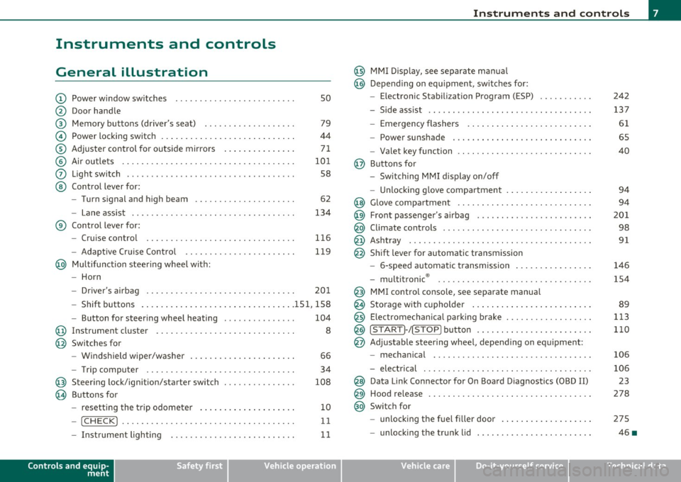
Instruments and controls
General illustration
(D Power window switches . . . . . . . . . . . . . . . . . . . . . . . . . 50
@ Door handle
@ Memory buttons (driver's seat) . . . . . . . . . . . . . . . . . . . 79
© Power locking switch . . . . . . . . . . . . . . . . . . . . . . . . . . . . 44
® Adjuster control for outside mirrors . . . . . . . . . . . . . . . 71
© Air outlets . . . . . . . . . . . . . . . . . . . . . . . . . . . . . . . . . . . . 101
0 Light switch . . . . . . . . . . . . . . . . . . . . . . . . . . . . . . . . . . . 58
@ Control lever for:
- Turn signal and high beam . . . . . . . . . . . . . . . . . . . . . 62
- Lane assist . . . . . . . . . . . . . . . . . . . . . . . . . . . . . . . . . . 134
® Control lever for:
- Cruise control . . . . . . . . . . . . . . . . . . . . . . . . . . . . . . . 116
- Adaptive Cruise Control . . . . . . . . . . . . . . . . . . . . . . . 119
@ Multifunction steering wheel with:
- Horn
- Driver 's airbag . . . . . . . . . . . . . . . . . . . . . . . . . . . . . . . 201
- Shift buttons ...... .. .. .... ........ .......... 151, 158
- Button for steering wheel heating . . . . . . . . . . . . . . . 104
@ Instrument cluster . . . . . . . . . . . . . . . . . . . . . . . . . . . . . 8
@ Switches for
- Windshield wiper/washer . . . . . . . . . . . . . . . . . . . . . . 66
- Trip computer ............... .. .. .. .. ....... .
@ Steering lock/ignition/starter switch ... .. ......... .
@ Buttons for
- resetting the trip odometer .......... .. .. .. ... .
- !CHECK] .... .... .. .... .. .... ............... .
-Instrument lighting . ....... .... .. .. .... .. .. . .
Controls and equip
ment Safety first
34
108
10
11
11
Instruments and controls
@ MMI Display, see separate manua l
@ Depending on equipment, switches for:
- Electronic Stabili zation Program (ESP)
- Side assist .. ... . .... .. .. .. .. .. .... .. .. .. ... .
- Emergency flashers .. .... .. .. .. ............. .
- Power sunshade . ... ... .. .. .. .. .... .. .. ... .. .
- Valet key function .. .. .. .. .... ....... ...... .. .
@ Buttons for
- Switching MMI display on/off
- Unlocking glove compartment
@ Glove compartment ...... .. .. .. .... .. ......... .
@ Front passenger 's airbag ............... ... .. .. . .
@ Climate controls ... .. .. .. .. .. .... .......... ... .
@ Ashtray .............. .. .... .. .. .. .. .... ..... .
@ Shift lever for automatic transmission
- 6-speed automatic transmission ....... .. ... ... .
- multitronic ® ....................... .. .... .. .
@ MMI contro l console, see separate manua l
@ Storage with cupholder ... .. ... .............. .. .
@) Electromechanical parking brake .............. .. . .
@ ISTAR T]-/ISTOP] button ........ .. ... .......... .
@ Adjustable steering wheel, depending on equipment :
- mechanical ............. .. .. .. ............. .
- electrical . ... ... .. .. .. .. .. .. .. .. .. ....... .. .
@ Data Link Connector for On Board Diagnostics (OBD II)
@ Hood release .......... .. .... .. .. .. .. ......... .
@ Switch for
unlocking the fuel fi ller door .............. .... .
- unlocking the trunk lid . .. ........ .. ... .. .. .. . .
Vehicle care
242
137
61
65
40
94
94
201
98
91
146
154
89
113
110
106
106 23
278
275
46 •
Technical data
Page 15 of 370
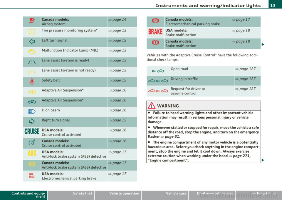
Canada models:
Airbag system
Tire pressure monitoring system*
L eft turn signal
Malfunct ion Indicator Lamp (MIL)
/ : Lane assist (system is ready)
Lane assist (system is not ready)
Safety belt
Adapt ive A ir Suspe nsio n*
-~ Adaptive Air Suspension"
D H igh beam
--
Q Right turn signal
CRUISE USA models:
Cruise contro l a ct ivate d =>page
14
=> page 15
=>page 15
=> page 15
=> page 15
=> page 15
=>page 15
=> page 16
=> page 16
=> page 16
=> page 15
=>page 16
Canada models: => page 16
Cruise control activated
USA models: => page 17
Ant i-lock brake system (ABS) defective
Canada models : => page 17
Anti-lock brake system (ABS) defective
USA models: PARK BRAKE Elect romecha nica l parki ng b rake
Controls and equip
ment Safety first
=:::, page 17
-
-
-
Instruments and warning
/indicator lights
(®)
BRAKE
--
Canada models: => page 17
E lectromechanical parking brake
USA model s: => page 18
Brake ma lf u nct ion
-Canada models: => page 18
B rake malfunction
Vehicles with the Adaptive Cru ise Control* have the following addi
ti onal check lamps:
Open road
i;:;::::::, 1111 i;:;::::::, D ri vi n g i n traffic
i;:;::::::, 1111 i;:;::::::, Request for dr iver to
assume con trol
& WARNING
=> page 12 7
=:::, page 127
=> page 127
• Failure to heed warning light s and other important vehicle
information may result in s erious personal injury or vehicle
damage.
• Whenever stalled or stopped for repair, move the vehicle a safe
distan ce off the road, st op the engine, and turn on the emergency
flasher =>
page 61.
• The engine compartment of any motor vehicle i s a potentially
hazardous area . Befo re you check anyth ing in the engine compart
ment, stop the engine and let it cool down. Always exercise
extreme caution when working under the hood=>
page 2 71,
"Engine compartment". .,.
Vehicle care Technical data
Page 17 of 370
App lies to vehicl es: wi th t ir e pr essure mon it o ring system
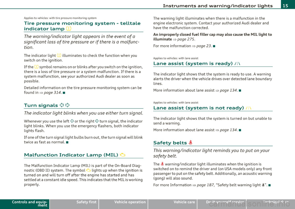
Tire pressure monitoring system - telltale
indicator Lamp '
The warning/indicator light appears in the event of a
significant loss of tire pressure or if there is a malfunc
tion .
The indicator light 'J illuminates to check the func tion when you
switch on the ignition.
If the
I symbol remains on or blinks after you sw itch on the ignit ion,
there is a loss of tire pressure or a system malfunction . If there is a
system malfunction, see your author ized Audi dealer as soon as
possible.
Detailed information on the tire pressure monitoring system can be
found in=>
page 314. •
Turn signals ¢ ¢
The indicator light blinks when you use either turn signal.
Whenever you use the left¢ or the right¢ turn signal, the indicator
light blinks. When you use the emergency flashers, both indicator
lights flash .
If one of the turn signa l light bu lbs burn out, the turn signal will blink
twice as fast as normal. •
Malfunction Indicator Lamp (MIL) !'.I
The Malfunct ion Indicator Lamp ( MIL) is part of the On-Board Diag
nostic (OBD II) system . The symbol lights up when the ignition is
t u rned on and will turn off after the engi ne has started and has
sett led at a constant idle speed. This indicates that the MIL is working
properly .
Controls and equip
ment Safety first
In
strum ents and warning /indicator lights
The warning light illuminates when there is a malfunction in the
engine electron ic system. Contact your author ized Audi dealer and
have the malfunction corrected .
An imp rope rly clo sed fu el fille r cap ma y al so cau se the M IL l ight to
illum in ate =>
page 2 75.
For more information=> page 23. •
App lies to vehicles : w ith lane ass ist
Lane assist (system is ready) /:
T he ind icator light shows that the system is ready to use . A warn ing
aler ts the driver when the veh icle drives over de tected lane boundary
lines.
More information about lane assist=>
page 134. •
Applies to vehi cles : wit h lane assis t
Lane assist (system is not ready) I
The indicator light shows that the system is turned on but unab le to
send a warn ing .
Mo re information about lane assist =>
page 134. •
Safety belts ,i
This warning/indicator light reminds you to put on your
safety belt.
The 4t warning/indicator light illuminat es when th e ignition is
switched on to rem ind the d river and (on USA models only) any front
pass enger to put on the safety b elt. Add itionally, an acoustic wa rning
(gong) will a lso sound.
For more Information=>
page 187, "Safety belt warning light~".•
Vehicle care Technical data
Page 121 of 370
__________________________________________ A_ d_a""" p:....- t_iv _ e_ C_ r_ u _is _ e_C_ o_n_ t_ r_ o_ L_....J_
Adaptive Cruise Control
Speed and distance control system
App lies to veh icles: wi th Ad aptive Cruise Cont ro l
Descr iption
Th e Adaptive Cruis e Control driv er assistance pro gram is
a c omb in ed spe ed an d dista nce contr ol syst em .
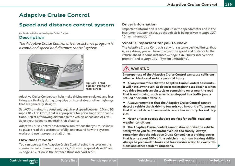
Fig . 107 Front
bumper: Po sition of
radar sensor
Adaptive Cruise Control can help make driving more relaxed and less
t irin g, particular ly d uring long trips on inters tates or o ther highways
that are genera lly straight.
S et ACC to maintain a constant, legal travel speed between 20 and 95
mp h (3 0 -150 km/h) t hat is a pprop riate for prev ailing traffic co ndi
tions. Select a following distance to the vehicle ahead and ACC w ill
adjus t you r speed t o mai ntain that dist an ce.
Adaptive Cruise Control has technical limitations that you must k now,
so p lease read this sectio n carefully, un de rstand how t he sys tem
wor ks and use it pro perly at all times.
How does it work?
You ca n operate the Adaptive Cruise Control using the lever on the
st eerin g wheel column=>
page 122, "H ow is the s peed stored ?" and
=>
page 125, " H ow is the distance (time inte rval) set?" .
Contro ls a nd e quip
m en t Vehicle
OP-eration
Driver information
Important information is bro ught up in the speedometer and in the
ins trumen t clus ter d is pla y as the ve hicle is be ing dr ive n=>
page 127,
"D river information" .
What is important for you to know
The Adaptive Cru ise Contro l is set with system-spec ified limits; that
is, as a driver, you will have to a djus t the s pee d and dis tan ce to t he
vehicle ahead in some in stances =>
page 130, "Driver intervention
promp t" and =>
page 131, "System lim itat ions".
ln. WARNING
Improper use of the Adaptive Cruise Control can cau se collisions,
other accidents and serious personal injury .
• Always remember that the Adaptive Cruise Contro l has limits -
it will not slow the vehicle down or maintain the set distance when
you drive towards an obstacle or something on or near the road
that is not mo ving, such as vehicles stopped in a traffic jam, a
stalled or disabled vehicle .
• Always remember that the Adaptive C rui se Control cannot
detect a vehicle that is driving towards you in your traffic lane and
that it cannot detect narrow vehicles such as motorcycles and bicy
cles .
• Never drive at speeds that are too fast for traffic , road and
weather conditions .
• The Adaptive Cruise Control cannot slow or brake the vehicle
safely when you follow another vehicle too closely . Always
remember that the Adaptive Cruise Control has a braking powe r
that is only about 30% of the vehicle 's maximum braking ability .
Always be prepared to b rake and ta ke e vasive action to a void colli-
sions and other accident situations . .,
Vehicle care Do-it-yourselt service iTechnical data
Page 136 of 370
IIIIL_!_A~u~d~i~l!:!a~n~e '...:a~s~s:!:is~t ~--------------------------------------------
Aud i Lane assist
Lane assist
Applies to veh icles : w ith lane assist
Description
Lane assist helps you keep your vehicle in your lane.
Lane assist uses a camera to detect lane boundary lines. If the system
detects that your vehicle is about to leave a lane boundary line, the
steering wheel
vibrates to alert the driver. If lane assist detects
boundary lines on both sides o f the veh icle's lane, the system enters
act ive standby mode, which is indicated by t he gree n indicator light
/: on the instrument cluster .
If the system is in active standby mode and the turn signal is acti
vated before driving over the boundary line , the warning does not
occur sinc e th e system allows for in tention al lane changes.
The system is designed for driving on freeways and expanded high
ways and th us works only at speeds of 40 mph (65 km/h) or more.
& WARNING
• Lane assist will not keep your vehicle in your lane. The system
only warns the driver when the vehicle is leaving the lane. The
driver is always responsible for keeping the vehicle in the lane.
• The camera is not able to detect all lane boundary lines and in
some cases might also detect lane structures or objects as
boundary lines. This can lead to incorrect warnings or warnings
that fail to go off at all.
• The camera's visibility can be impaired by vehicles ahead of
you, for instance, or by rain, snow, heavy spray or light shining
into the camera lens. This can cause lane assist to fail to detect
boundary lines. •
Applies to veh icles: wit h lane assist
Activating and deactivating
Fig. 126 Turn signal
lever: Lane assist
button
Fig. 127 Windshield:
Lane assist camera
viewing window
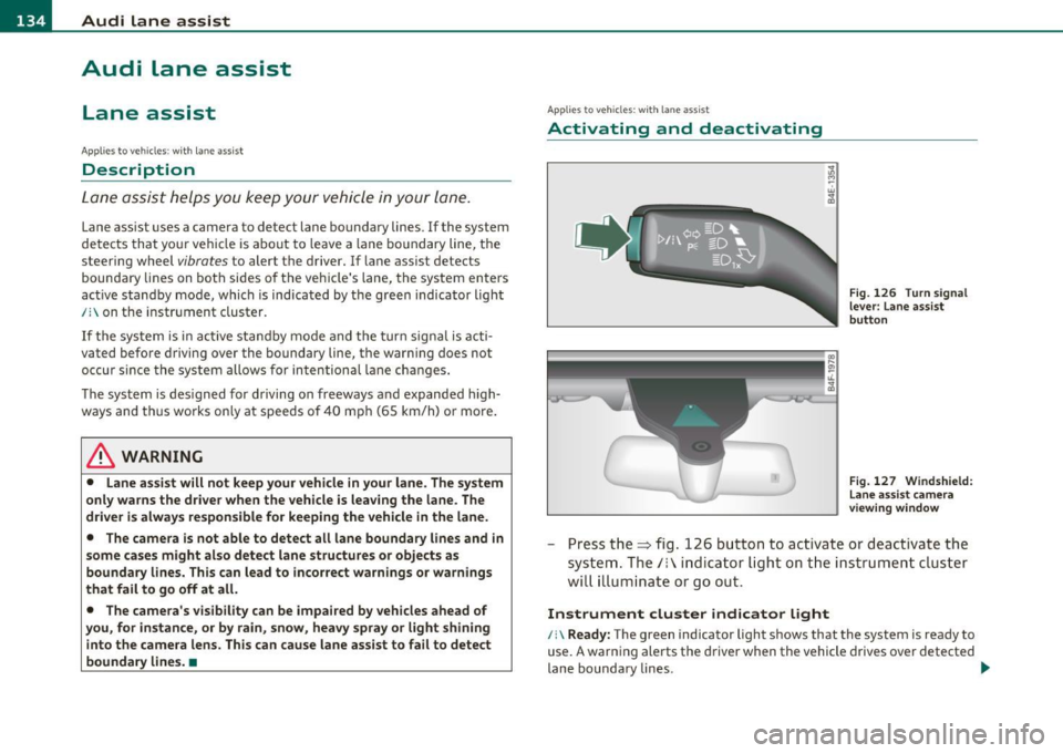
-Press the=> fig . 126 button to act ivate or deactivate the
system. The/: ind icator light o n the instrument cluster
will illumi nate or go out.
Instrument cluster indicator light
/:\Ready: The green indicator light shows that the system is ready to
use. A warning alerts the driver when the vehicle drives over detected
lane boundary lines . -.,
Page 137 of 370

Audi lane assist -________________ lff'II
Not ready: The yellow indicator light shows that the system is
turned on but unable to send a warning. This can be due to the
following:
• Th ere are no boundary lines, or there is only one boundary line
present.
• The boundary lines are not detected (e .g . due to snow, dirt, wet
conditions or light shining into the camera lens).
• More than two boundary lines (such as at construction sites) are
located in the vehicle's lane.
• Th e vehicle's speed is below the speed needed to activate it, which
is about 40 mph (65 km/h) .
• Th e lane is narrowe r than about 8
ft. (2.5 m), or wider than about
16 ft. (5 m).
• The curve is too sharp.
Notes on the instrument cluster display
When the lane assist turns off automatically, the instrument cluster
indicator goes out and one of the fo llowing messages appears on the
display:
Audi lane assist not available: currently no sensor vision
Thi s message appears when the camera can no longer function
because it cannot detect the boundary lines. This may be due to the
following:
• Th e exte rior side of the camera viewing window=>
page 134,
fig. 127 is covered with dirt or ice. Clean this part of the windsh ield.
• Th e came ra viewing window is fogged up on the inside. In this
case, wait until the fog disappears before turning lane assist on
again.
• Th e system was unable to detect boundary lines over an extended
period of time due to road conditions (such as snow-cove red lanes).
Do not turn lane assist on aga in until the lines can be more easily
detected.
Audi lane assist currently not available
Controls and equip
ment Safety first A temporary malfunction
is preventing lane assist from operating .
Tr y turning on lane assist again at a lat er time.
Audi lane assist: system fault
The system shou ld be checked by an authorized Audi dealer or other
qualified wo rkshop.
[ i ] Tips
• Make sure that the camera viewing window => page 134, fig. 127
is not covered by stickers or similar objects.
• Always keep the camera viewing w indow clean. This can us ually be
done by operating the windshie ld wipers. •
Applies to vehicles: wi th lane assist
MMI settings
You can use the fv1fv1I to adjust the warning time and
steering wheel vibration.
-Select: Function button [CAR ]> Systems *> Audi lane
assist.
Setting the warning time
Early: This setting warns the driver before a wheel touches the
detected lane boundary line. The warning depends on the vehicle's
angle as it approaches the boundary line. If you approach a boundary
line gradually, the warn ing will occur earlier. If you approach the
boundary line at a very sha rp angle, the warn ing will occur just befo re
a wheel touches the line.
Medium : In this setting, the warning time adjusts to the characteris
tics of the road and the vehicle speed. The wa rning occurs later fo r
curves and occurs earlier for straight stretches of road . The warning
occurs later on narrow roads than on wide ro ads.
Late : This setting warns the driver when a wheel dr ives over the
detected lane boundary line.
Vehicle care Technical data
Page 138 of 370
1111....__A_ u_ d_i_ l_ a_ n_ e_ a_s_ s_ is_t _________________________________________________ _
Setting the steering wheel vibration
When ad justing the steering wheel v ibration, the s teer ing whee l
vibrates so that you can check the in tensity you have set.
Cl] Tips
• When mak ing t he ad justment, lane assist is not act ivated . The
steering wheel vibrates briefly only to ass ist you in chang ing the
sett ing.
• Your settings a re automatically stored and assigned to the remote
cont rol key being used .•
Page 139 of 370

_________________________________________________ A_ u _ d_ i_ s_ id_ e_ a _ s_s _ i_s _t _ __.fflll
Audi side assist
Lane Change Assistant
Applies to veh icles: with side ass ist
Descr iption
The side assist helps you when changing lanes.
AU DI
Fi g. 1 28 Rear
b um per: Positio n of
r adar senso rs ( not
v isible on o utside)
F ig. 129 Signa l light
o n th e outside mi rror·
driver's s ide
Side ass ist uses radar sensors (not visible on outside)=> fig. 128 to
help the driver check blind spots, and see what is happening in traffic
behind the vehicle::::>
page 138, fig. 131.
Signal lights are built into both outside mirrors=> fig. 129. The signal
light on the left outs ide mirror assis ts when moving over into the left
Con tro ls a nd e quip
m en t Vehicle
OP-eration
lane and the signal light on the right outs ide mirror assists when
moving over into the right lane.
Th e signa l light comes on to tell you that side ass ist has detected a
vehicle on that side and that the position of this other ve hicle should
be taken into account if yo u were to change lanes. This is called the
inform ational stage signa l=> page 139 . T he informational stage
signa l is designed so that you not ice it on ly when you are looking in
the outside mirror.
When you activate the turn signal and side assist detects a vehicle in
a notab le location, the correspond ing signal on the outside mirror
flashes briefly and brightly several times. This is the
ale rt stage
s ign al=>
page 139. •
Applies to v ehicles: with side ass ist
Activating and deactivating
~Jj D r:.i I
Activating
Fig . 130 Coc kpit: Side
assist b utt on
- Press the=> fig. 130 button. The indica tor on the button
lights up . ..,
Vehicle care Do-it-yourselt service iTechnical data
Page 140 of 370

lffll.___A_ u_ d_i_ s_ id_ e_ a_s _s_ i_ s _t _________________________________________________ _
Deactivating
- Press the button again . T he indicator light o n the b utton
goes out.
The system works at speeds faster tha n 19 mph (30 km/h) .
& WARNING
• Imp roper reliance on the side assist system can cause collisions
and seriou s per sonal injury:
- Never rely only on s ide ass ist when changing lanes.
- Alway s che ck rear view mirror s to m ake sure that it i s safe to
change lanes.
• Side a ssist cannot detect all vehicles under all condition s
danger of accident!
• Side a ssi st cannot detect vehicle s in time to alert you when
they approach from beh ind at very high speed, or fall drop back
very quickly .
• The radar sen sor's
v is ion can be reduced or entirely blocked by
rain , snow, and heavy spray . This can result in side as sis t not
adequately detecting vehicle s or , in some cases, not detecting
them at a ll. Alway s keep an eye on the dir ection you are traveling
and the rele vant area around the vehicle.
• Please note that side assist indicates there are approaching
vehicles , or vehicles in you r blind spot, only after you r vehicle has
reached a driving speed of at lea st 19 mph (30 km/h).
• Side assist signal doe s not work around t ight corners (turning
radius les s than 328 feet , or 100 m).
• Side assist is no replacement for the driver 's full attention . The
driver alone is respon sible for lane change s and s imilar driving
maneuvers. Always keep an eye on the direction you are traveling
and the relevant area around the vehicle.
0 Note
• T o ensure that you do not adversely affe ct s ide as sist , do not block
the area on the rear b umper where the radar sensors are located with
fo reign objects (such as st ic kers or b icycle ra cks).
• Make s ure that the signal light on the o utside mi rror is not
bloc ked by stic ke rs or othe r items.
[I) Tips
• Side ass ist automatica lly deac tivates if it detects that the radar
sensors are blocked=>
page 144. The indicator light on the button
goes out.
• Th e area on the bumper w he re the radar sensors are located must
c ons istent ly rema in free of snow, i ce, a nd he avy soiling so that s ide
assist can function properly. Follow the add itiona l notes on
=>
page 144.
• Add it iona l tinting on t he front side windows can ma ke it harder to
see and correctly u nders tand the s ig nal light on the outs ide mirro r.
• For Decla ration of Compliance to United States FCC and Industry
Canada regulations=>
page 349. •
Applies to vehicl es : w it h side ass ist
Sensor detection area
, D i
Fig. 131 S chem ati c
illustrat io n : S ensor
detection are a
~