service indicator AUDI A6 2011 Owners Manual
[x] Cancel search | Manufacturer: AUDI, Model Year: 2011, Model line: A6, Model: AUDI A6 2011Pages: 370, PDF Size: 87.15 MB
Page 13 of 370
0 Note
Never run the tan k comp letely d ry . An irregular s upply of f ue l can
cause engine misfiring and fue l cou ld enter the ex ha ust system . T he
c ata lytic co nve rter co ul d the n overhea t and be damaged .•
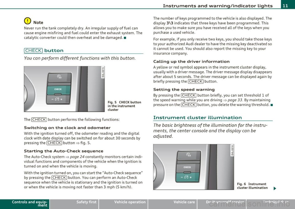
[ C HECK ) button
You can per form differen t functions wi th this button.
Fig . 5 CHE CK button
i n the in strume nt
clu ste r
Th e [ C H ECK] bu tton perfo rms the fo llowing func tions :
Switching on the clock and odometer
With the ignition tu rned off, the odome ter read ing and the dig ita l
clock with date d isplay can be switched on for abo ut 30 seconds by
pressin g the [
CHECK ] button ~ fig . 5.
Starting the Auto-Check sequence
The Auto-Check system~ page 2 4 constantly monitors ce rtain indi
vidual functions and components of the vehicle when the ignit ion is
tur ned on and w hen the vehicle is movi ng.
With the ignition turned on, yo u can sta rt the "A uto-Check sequence"
by pressing the
!CHECK ] button. You can perform an Auto -Check
sequence whe n the veh icle is st ationa ry a nd the ignition is turned on
or when the vehicle is moving not faster than 3 mph (5 km/h) .
Control s and equ ip
m ent Vehicle OP-eration
Instruments and warning /indicator lights
The nu mber of keys programmed to the vehicle is a lso displayed . The
di splay
3\3 indic ates th at three keys have been programmed . T his
allows you to make sure you have received all of the keys w hen you
purc hase a used ve hicle.
For example, if you o nly receive two keys, yo u sho uld ta ke tho se keys
to your a uthorized Audi dealer to have the missing key deactivated so
i t ca nn ot be used. You sh ould also re port the mis sing key to you r
insurance compa ny.
Calling up the driver information
A ye llow or red symbol appears in the instrument cluster display,
us ua lly w it h a dr ive r mes sage . T he driver message display di sappe ars
after about 5 seco nds. The driver message can be displayed again by
br iefly p ressing t he
[CHECK ] but to n.
Setting the speed warning
By press ing t he I CH ECK] button br iefly, you can set t hreshold 1 of
the speed warning while yo u are driving ~
page 33. By maintaining
pressure on the
I CHECK ] button, you de lete the warning th reshol d.•
Instrument cluster illumination
The basic brig htness of the illumination for the inst ru
ments, the center console and the display can be
a dju sted.
Fig. 6 Instrument
clu ste r illum inat ion .,,_
Vehicle care Do-it-yourselt service iTechnical data
Page 21 of 370
Driver information display
Introduction
General notes
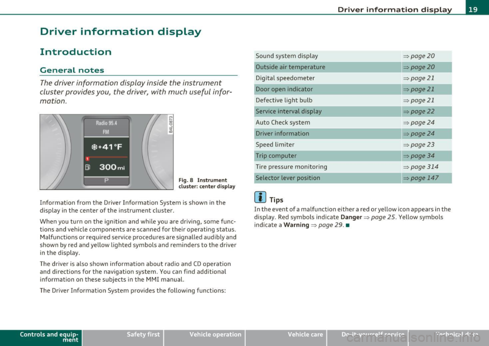
The driver information display inside the instrument
cluster provides you, the driver, with much useful infor
mation .
Fig. 8 Instrument
cluster: center display
Informat ion from the Driver Information System is shown in the
display in the center of the instrument cluster.
When you tu rn on the ignition and while you are driving, some func
tions and vehicle components are scanned for their operating status.
Malfunctions or required service procedures are signalled audibly and
shown by red and yellow lighted symbols and reminders to the driver
in the display .
Th e driver is also shown information about radio and CD operat ion
and directions for the navigation system. You can find additional
information on these subjects in the MMI manual.
The Driver Information System provides the follow ing functions:
Con tro ls a nd e quip
m en t Vehicle
OP-eration
Driver information display
Sound system display ~page20
Outside a ir temperature ~page20
Digital speedometer ~ page21
Door open indicator ~page21
Defective light bulb ~page21
Service interval display ~page22
Auto Check system ~page24
Driver information ~page24
Speed limiter ~page23
Trip computer ~ page3 4
Tire pressure monitoring ~page314
Selector lever position ~ page 147
(I] Tips
In the event of a malfunction either a red or yellow icon appears in the
display . Red symbols indicate
Danger ~ page 25. Yellow symbols
indicate a
Warning ~ page 29. •
Vehicle care Do-it-yourselt service iTechnical data
Page 25 of 370
On-Board Diagnostic system (OBD)
Malfunction Indicator Lamp (MIL)
The Malfunction Indicator Lamp (MIL) in the instrument cluster
~ page 12, fig. 7 is part of the On-Board Diagnostic (OBD II) system.
The warn ing/ind icator light illuminates when the ignition is switched
on and goes out after the engine starts and the idle has stabilized.
This indicat es that the MIL is working properly.
If the light does not go out after the engine is started, or illuminates
while you are driving , a malfunction may exist in the engine system.
If the light illuminates, the catalytic co nverter could be damaged .
Continue driving
with reduced power (avoiding sustained high
speeds and/or rapid accelerations) and have the condition corrected.
Contact your authorized Audi dealer .
If the light illuminates, the electronic speed limiter may also be
malfunctioning. For more information~
page 23, "Electronic speed
limiter".
An improperly closed fuel filler cap may also cause the MIL light to
illuminate ~
page 275. •
On-Board Diagnostics
Contro ls a nd e quip
m en t
Fig . 15 Locat ion of
Data Link Connector ( DLC )
Vehicle OP-eration
Driver information display
On-Board Diagnostics monitors the components of your emission
control system. Each monitored component in your engine system
has been assigned a code. In case of a malfunction, the component
will be identified and the fault stored as a code in the control module
memory .
The MIL light may also illuminate if there is a leak in the on-board fue l
vapor recovery system. If the light illuminates after a refuelling, stop
the vehicle and make sure the fuel filler cap is properly closed
~ page 275 .
In order to make an accurate diagnosis, the stored data can only be
displayed using specia l diagnostic equipment (generic scan too l for
OBD).
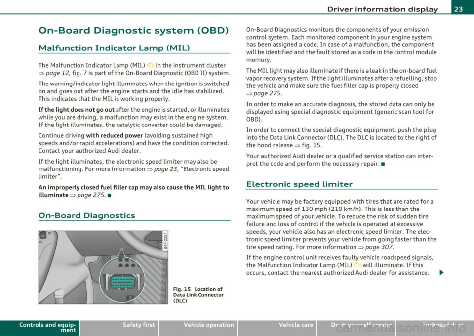
In order to connect the special diagnostic equipment, push the plug
into the Data Link Connector (DLC). The DLC is located to the right of
the hood release~ fig . 15.
Your authorized Audi dealer or a qualified service station can inter
pret the code and perform the necessary repair.•
Electronic speed limiter
Your vehicle may be factory equipped with tires that are rated for a
maximum speed of 130 mph (210 km/h). This is less than the
maximum speed of your vehicle . To reduce the risk of sudden tire
failure and loss of control if the vehicle is operated at excessive
speeds, your vehicle also has an electronic speed limiter. The elec
tronic speed limiter prevents your vehicle from going faster than the
tire speed rating. For more information ~
page 307.
If the engine con trol unit receives faulty vehicle roadspeed signals,
the Malfunction Indicator Lamp (MIL) will illuminate. If this
occurs, contact the nearest authorized Audi dealer for ass istance . .,.
Vehicle care Do-it-yourselt service iTechnical data
Page 30 of 370
Driver information display
Engine oil pressure malfunction
~
The red engine oil pressure warning symbol requires
immediate service or repair. Driving with a low-oil-pres
sure indication is likely to inflict severe damage to the
engine .
If the "t=:;r: symbol appears in the display and blinks, the oil
pressure is too low. An additional driver message can also be
displayed by pressing the
[CHECK] button :
Switch off engine ! Oil pressure too low
Immediate actions
-Pull off the road .
- Stop the vehicle.
- Turn off the engine.
- Check the engine oil level with the dipstick=> page 283.
Dipstick readings checks too low
- Top off oil to the proper level=> page 284 .
Make sure that the oil pressure warning symbol "t=:;r:
appears no longer in the display before you start driving
again.
Dipstick reading checks OK
- If the oil pressure warning symbol "t=:;r: starts flashing
again even though the engine oil level checks OK on the
dipstick,
do not continue driving and do not let the
engine run in idle.
Instead, contact your authorized Audi
dealer for assistance.
W Tips
• The engine oil pressure symbol 't=1: is not an indicator for a low
engine oil level. Do not rely on it. Instead, check the oil level in your
engine at regular intervals, preferably each time you refuel, and
always before going on a long trip.
• The yellow oil level warning indication "" requires oil refill or
workshop service without delay. Do not wait until the red oil pres
sure warning
't=1: starts to flash before you respond to the low oil
level warning -. By then, your engine may already have suffered
serious damage. •
Steering malfunction i
If there is a malfunction in the electronic steering column
lock, the steering cannot be unlocked.
If the i symbol in the display blinks, there is a malfunction
in the electronic steering column lock . An additional driver
message can also be displayed by pressing the [
CHECK ]
button:
Do not drive vehicle: Steering defective
-Contact your nearest authorized repair facility.
- Do
not tow your vehicle .
& WARNING
Your vehicle must not be towed in the event of a malfunction in
the electronic steering column lock because it cannot be steered due to the locked steering. If it is towed with the steering locked,
there is the risk of an accident. •
Page 34 of 370
Driver information display
Applies to veh icles : w ith eng ine s peed limitat ion
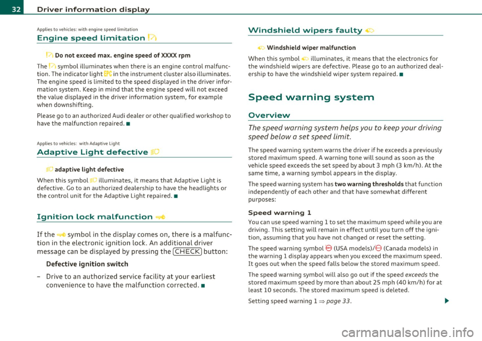
Engine speed limitation .?i
11'1 Do not exceed max. engine speed of XXXX rpm
The -symbol illuminates when there is an engine control malfunc
tion. The indicator light in the instrument cluster also illuminates.
The engine speed is limited to the speed displayed in the driver infor
mation system. Keep in mind that the engine speed will not exceed
the value d isp layed in the drive r informat ion system, for example
when downshifting.
Please go to an authorized Audi dealer or other qualified workshop to
have the malfunction repaired.•
Applies to vehicles: wi th Adap tive Light
Adaptive Light defective
adaptive light defective • r
When this symbol illuminates, it means that Adaptive Light is
defective. Go to an authorized dealership to have the headlights or
the control unit for the Adaptive Light repaired. •
Ignition lock malfunction ..e
If the symbol in the display comes on, there is a malfunc-
t ion in the electronic ignition lock. An additional driver
message can be displayed by pressing the [CHECK] button:
Defective ignition switch
-Drive to an aut horized service facility at your earliest
convenience to have the malfunction corrected.•
Windshield wipers faulty , . .>
.... Windshield wiper malfunction
When this symbol . illuminates, it means that the electronics for
the windshield wipers are defective . Please go to an authorized deal
ership to have the windshield wiper system repaired. •
Speed warning system
Overview
The speed warning system helps you to keep your driving
speed below a set speed limit.
Th e speed warning system warns the driver if he exceeds a previously
stored maximum speed. A warning tone will sound as soon as the
vehicle speed exceeds the set speed by about 3 mph (3 km/h). At the
same time, a warning symbol appears in the display.
The speed warning system has
two warning thresholds that function
independently of each other and that have somewhat different
purposes :
Speed warning 1
You can use speed warning 1 to set the maximum speed while you are
driving. This setting w ill remain in effect until you turn off the igni
tion, assum ing that you have not changed or reset the setting .
Th e speed warning symbo l
'8 (USA models)/ 8 (Canada mode ls) in
the warning 1 display appears when you exceed the maximum speed.
It goes out when the speed falls be low the stored maximum speed.
Th e speed warning symbol will also go out if the speed
exceeds the
stored maximum speed by more than about 25 mph (40 km/h) for at
least 10 seconds. The stored maximum speed is deleted.
Sett ing speed warn ing 1
=> page 33. ~
Page 65 of 370
High beam l[D
-Push the lever forward ® to switch on the high beam.
- Pull the lever back towards you to switch off the high
beam.
H eadlight flasher l[D
- Pull the lever toward the steering wheel© to use the
headlight flasher.
Notes on the se fea ture s
• The turn signals only work with the ignition turned on. The indi
cato r lights ¢ or¢ in the instrument cluster=>
page 12 also blink.
• After you have turned a corner, the turn signal switches off auto
matically.
• The
high beam works only when the headlights are on. The indi
cato r light [D in the instrument cluster illuminates when the h igh
beams are on.
• T he
headlight flasher works only as long as you ho ld the lever -
even if there are no lights turned on. The indicator light~D in the
instrument cluste r illuminates when yo u use the headlight flasher.
0 Note
Do no t use the high beam or head light flasher if you know that these
could blind oncoming traffic .•
Con tro ls a nd e quip
m en t Vehicle
OP-eration
Clear vision
Interior lights
Front interior lights
The interior lights include reading lights for both the
driver and the front passenger.
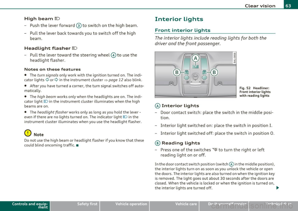
© Interior lights
Fig . 52 Headli ner:
F ron t inte rior lights
wit h rea ding lights
- Door contact switch : place the switch in the middle posi-
tion .
- Interior light switched on: place the switch in position
I.
-Interior light switched off: place the switch in position 0.
® Reading lights
- Press one of the switches '* to turn the right or left
reading light on or off .
In the door contact switch position (switch @in the middle position),
the interior lights turn on as soon as you unlock the vehicle or open
the doors. The interior lights are also turned on when the ignition key is removed. The light goes out about 30 seconds after the doors are
closed . When the vehicle is locked or when the ign ition is turned on,
the interior lights are turned off.
~
Vehicle care Do-it-yourselt service iTechnical data
Page 115 of 370

On the road -_______________ __.
the driver's door is opened. In t his instance, the steer ing is not
locked. The s teer ing is locked:
• If you press the
(STOP) button again for more than 1 second .
• If you close the driver 's door and lock yo ur vehicle from the
outs ide .•
Electromechanical parking brake
Operation
The electromechanical parking brake replaces the hand
brake.
Fi g. 104 Cente r
co nsol e: Pa rki ng brak e
- Pull the switch to apply the parking brake ~fig . 104. The
indicator light in the switch will come on.
- Step on the brake pedal or the accelerator pedal and press the switch at the same time to re lease the parking bra ke.
The indicator light in the switch wil l go out .
Your vehicle is equipped with an electromec hanical park ing brake
w hich replaces the handb rake. The parking brake is d esigned to
prevent the vehicle from ro lling unintent iona lly .
Con tro ls a nd e quip
m en t Vehicle
OP-eration
In addit io n to the normal functions of a traditional hand brake, the
ele ct romechan ica l parki ng br ake p rovides various convenience and
safety functions .
Emergency brake
An emergency brake ensures that the vehicle can be slowed even if
t he
normal bra kes fail => page 115, "E merge ncy bra king" .
Indicator lights
• If the pa rking brake is applie d with the ig nition turned on , the
indicator light in the instrument cluster (U.S models:
:'.Ii , Canadian
mode ls: © ) and i n the swi tch
(e)) w ill come o n.
• If the parking brake is applied with the ign ition
turned off , the
indicator light in the in strument cluste r (U.S. models:
::'.l, , Ca nadian
models: ©) and in the switch© will come on for about 30 seconds
and then go out .
& WARNING
If the vehicle is stati onary and the transmi ssion is engaged with
the eng ine running, the e ngine should not be speeded up (e.g.
m anuall y from under th e hood ). Otherwi se the vehicle will st art to
mo ve -you run the risk of an ac cident.
0 Note
If the warning/ind icator light (U.S. models: BRAKE , Canadian mode ls:
(Ci)) ) flashes in the ins trumen t clus ter, t here is a brake sys tem
malfunction. By press ing the [
CHECK) b utton, yo u can bri ng up a
dr iver message which explains the malfu nction in mo re deta il.
If the
message
Parking brake! Please contact workshop appea rs, the re is a
parking brake malfunction which yo u should have repaired immedi-
ately by an au thorized dealership=>
page 26 . ..
Vehicle care Do-it-yourselt service iTechnical data
Page 129 of 370

__________________________________________ A_ d_a""" p:....- t_iv _ e_ C_ r_ u _is _ e_C_ o_n_ t_ r_ o_ L_....Jfflll
Driver information
Applies to veh icles: with Adaptive C ruise Cont ro l
Displays in the instrument cluster
Depending on the driving situation, driver information is
displayed in the instrument cluster .
@ Speedometer and indicator light display
@ Display in the instrument cluster
Fig. 114 O vervi ew
in strume nt clu ster
@ Speedomet er and indicator light display
Important information concerning vehicle operation with Adaptive
Cru ise Control is shown in display area @. T he desired speed you set
is indicated in the speedometer (L ED lights around the edge).
Th e ind ic ator lig hts show whether the sys tem has detec ted a ve hicle
traveling ahead.
@ Display in the instrument cluster
In d isp lay area @ information from the navigation system * and the
t rip compu ter is displayed in a ddition to info rmation abou t Ad apt ive
Cru ise Control.
You can select among the different information by repeated b rief
taps on the
I RESE T! but ton on the windshield w iper lever~ page 35,
"Operation" .
Contro ls a nd e quip
m en t Vehicle
OP-eration
Certain pieces of in format ion in the bottom part of the display are not
show n perm anent ly . In fo rmat ion is dis played on ly if you set or
change the speed setting, change the t ime interval, when messages
are displayed or if the Adaptive Cr uise Control is tu rned off for safety
reasons .•
App lies to v ehicle s: with Adaptive C ru ise Cont rol
Display in the speedometer
Desired speed
Fig. 1 15 Di spl ay in
th e sp eedometer
The des ired speed set by the driver is displayed by a red LED.
If the desired speed was set between two lines o n the speedometer
using the
[ SET ! button, the two closes t light em itting diodes will
come on~ fig. 115 .
The system allows on ly speeds to be set between 20 to 95 mph (30
to 150 km/h) to be set. This speed range is fa int ly ill umina ted in the
speedometer (L ED lights) .
Indicator lights (symbols)
• ""~ Open ro ad: The indicator light 11 "~ shows that ACC is active
and that no moving veh icle has been detected with in range of the
radar sensor up ahead in your lane of travel. The set speed is main-
tained. .,,_
Vehicle care Do-it-yourselt service iTechnical data
Page 175 of 370
HomeLink® -_______________ __.
9. The emergency flashers will flash three times (after about
15-60 seconds) when the programming is successful.
Release the button on the remote control.
-To program more devices, repeat steps 4 to 9.
10. Press and hold the trained Homelink ® button and
observe the indicator light©~
page 172, fig. 163.
- If the indicator light is solid/continuous, programming is
complete and your device should activate when you press
and release the trained Homelink ® button.
- If the indicator light blinks rapidly for 2 seconds and is then a solid/continuous light, proceed with phase 3 to program a rolling code device.
Phase 3: rolling code programming
- A second person on a ladder who can safely reach the
garage door opener motor is recommended.
11 . Locate the "learn" button on the garage door opener
motor (refer to the operating instructions for the opener,
as the location of this button may vary by manufacturer) .
12. Press and release the learn button on the garage door
opener motor.
-Note: once the button is pressed, there are 30 seconds in
which to initiate the next step.
13. On the Homelink® keypad inside the vehicle, firmly press
and hold the Homelink® button previously programmed
in phases 1 and 2 for two seconds and release. Repeat this
sequence
twice .
Contro ls a nd e quip
m en t Vehicle
OP-eration
-Some vehicles may require the press/hold/release
sequence up to three times to complete the training
process.
- Homelink ® should now activate your rolling code
equipped device.
If the 5 minute time limit is exceeded, the emergency flashers will
flash one time
to indicate that the process has been terminated. In
this case, repeat steps 4 through 9.
If the emergency flashers do not flash three times (after about 15 -
60 seconds), programming was not successful. In this case, repeat
steps 4 through 9.
Remote control units for garage door openers in Canada are set to
stop transmitt ing radio frequency signals after two seconds. This
time may not be sufficient for the Home link® system to learn the
radio frequency signal. Perform all other steps as described above.•
Applies to veh icles: with Hom elin k® un iversa l rem ote cont rol
Operating the Homelink ® transmitter
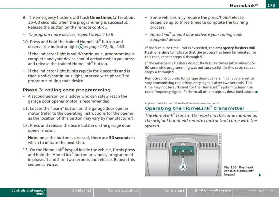
The HomeLink ® transmitter works in the same manner as
the original hand held remote control that came with the
system.
~ ;;;;;~~~~ ~=;==~~~ ;;;;:;;;~,~!:
{I I I I I~ i 111111 1,A
Fig. 1 65 Overhead
conso le: Homelink®
keypad
Vehicle care Do-it-yourselt service iTechnical data
Page 219 of 370

Aside from their norma l safety function, safety be lts work to he lp
kee p th e dr iver or fron t p asse n ger in posi tion in t he even t of a c olli
sion so that the side cu rtain a irbags can provide protection.
T he a irbag system is not a substitute for your safety belt . Rathe r, it is
par t of the ove rall o ccu pan t res traint syste m in your vehicle . A lw ay s
remember t hat the airba g system can on ly help to protect you if you
a re we ari ng your safety bel t and wearing it prop erly. Thi s is ano ther
reaso n why you s hou ld always wea r your safety be lts, not just because
th e law requi re s you to do so=>
page 187 , "G ene ral not es".
It is i mpo rtant to re m ember that while the s ide curta in airbag system
is des igned to help re duce the likelih ood of serious injuries, ot her
i n jur ies, fo r exa mple, sw elling, br uising, a nd m inor ab rasions can
also be assoc iated wit h these airbags upo n dep loyment . Remembe r
t o o , these a irbags w ill d eploy only on ce an d on ly in ce rt ain kinds of
acc idents -yo ur safety belts are always there to offer protection.
The side curtain airbag system basically consists of:
• Th e electronic co ntro l mo dule an d external side impact sensors
• The side c urtai n airbags above the fro nt an d rea r side windows
• Th e airba g indic ator ligh t in the ins trumen t panel
Th e a irbag system is monitored elec tron ically to make certai n it i s
functioning prope rly at a ll times . Each time yo u turn on the ignition,
t h e airbag sys tem indicator ligh t w ill com e on for a few seconds (s elf
diagnostics) .
The side curtain airbag is not activated:
• if the ignition is turned off,
• in side co llisions when the accelerati on measured by the sens or is
t o o low,
• in rear-end collisions,
• in rollove rs.
Safety first Vehicle OP-eration
Airbag system
& WARNING
• Safety belts and the airbag system will only provide protection
when occupants are in the proper seating position =>
page 75,
"General recommendations ".
• If the airbag indicator light comes on when the vehicle is being
used, have the system inspected immediately by your authorized
Audi dealer. The side curtain airbag may not work properly even
when the vehicle acceleration in a side collision is high enough to activate the airbag.~
How side curtain airbags work
Side cu rtain ai rbags c an wo rk to gethe r w it h sid e airba gs
to h elp r ed uce the risk of h ead and upp er tors o inju rie s f or
o cc u pan ts who are pr operly restr ained.
Fig . 188 Illu str ation
of principle: Inflated
side curt ain airbag s on
the left side
Th e side curtain airbags in flate between the oc cupan t and t he
w indows on the side of the vehicle t hat is struck in a sid e co llision
=> fig. 188.
Wh en the sys tem is tr igg ered, the side curta in airbag is filled w ith
pro pell ant gas and breaks th rough a seam above the front and rear
s ide w indow s iden tifi ed b y the AIRBAG label. In or der to help pro vid e
this additional protection, the side c urta in airbag must inflate with in
th e bl ink of an eye at very hi gh speed and wi th gre at force. The side ._
Vehicle care Do-it-yourselt service iTechnical data