ESP AUDI A6 ALLROAD 1999 C5 / 2.G Pneumatic Suspension System
[x] Cancel search | Manufacturer: AUDI, Model Year: 1999, Model line: A6 ALLROAD, Model: AUDI A6 ALLROAD 1999 C5 / 2.GPages: 44, PDF Size: 2.47 MB
Page 28 of 44

28
F
F
F
F
F
S
F
S
S F
3
1
7
52/25
2/50
2/49
2/05
2/04
2/01
2/02 9
10
4
8
System components
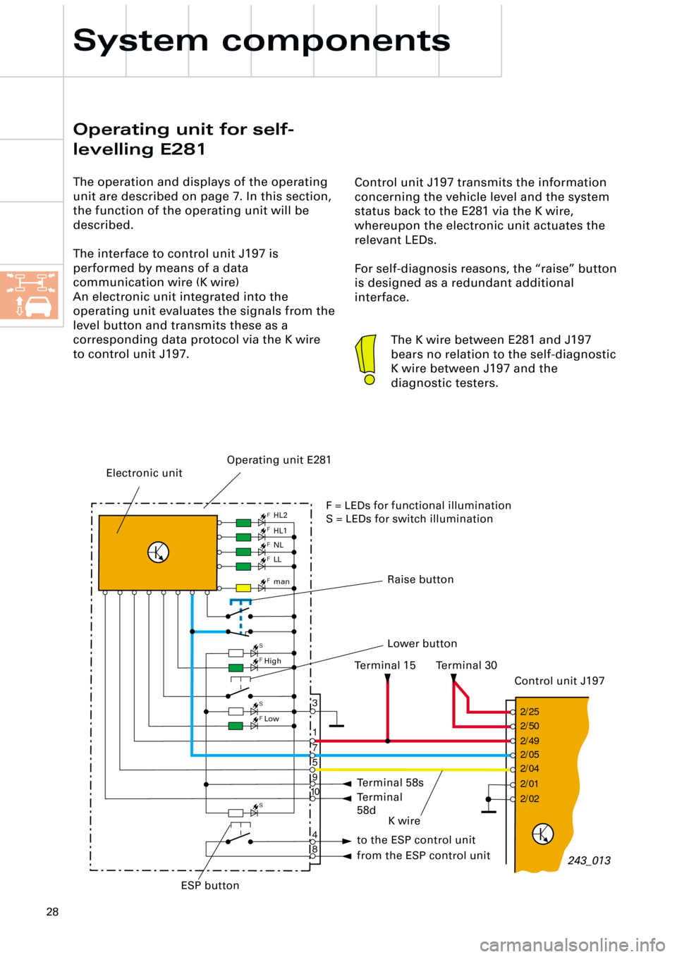
Control unit J197 transmits the information
concerning the vehicle level and the system
status back to the E281 via the K wire,
whereupon the electronic unit actuates the
relevant LEDs.
For self-diagnosis reasons, the “raise” button
is designed as a redundant additional
interface.
Operating unit for self-
levelling E281
The operation and displays of the operating
unit are described on page 7. In this section,
the function of the operating unit will be
described.
The interface to control unit J197 is
performed by means of a data
communication wire (K wire)
An electronic unit integrated into the
operating unit evaluates the signals from the
level button and transmits these as a
corresponding data protocol via the K wire
to control unit J197.
243_013
The K wire between E281 and J197
bears no relation to the self-diagnostic
K wire between J197 and the
diagnostic testers.
Electronic unit
Control unit J197 Terminal 30 Terminal 15
Raise button
K wire
Operating unit E281
Terminal 58s
Terminal
58d
to the ESP control unit
from the ESP control unit
HL2
HL1
NL
LL
man
High
Low
Lower button
ESP buttonF = LEDs for functional illumination
S = LEDs for switch illumination
Page 29 of 44

29
CAN information exchange
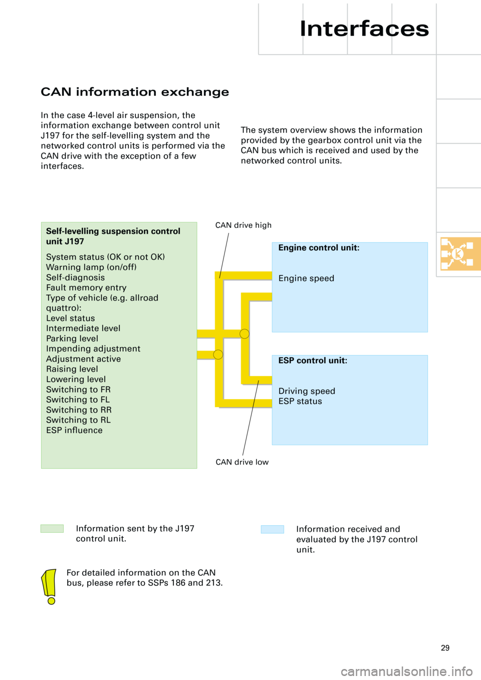
In the case 4-level air suspension, the
information exchange between control unit
J197 for the self-levelling system and the
networked control units is performed via the
CAN drive with the exception of a few
interfaces.
Interfaces
The system overview shows the information
provided by the gearbox control unit via the
CAN bus which is received and used by the
networked control units.
Information sent by the J197
control unit.Information received and
evaluated by the J197 control
unit.
Engine control unit:
Engine speed
Self-levelling suspension control
unit J197
System status (OK or not OK)
Warning lamp (on/off)
Self-diagnosis
Fault memory entry
Type of vehicle (e.g. allroad
quattro):
Level status
Intermediate level
Parking level
Impending adjustment
Adjustment active
Raising level
Lowering level
Switching to FR
Switching to FL
Switching to RR
Switching to RL
ESP influence CAN drive high
CAN drive low
ESP control unit:
Driving speed
ESP status
For detailed information on the CAN
bus, please refer to SSPs 186 and 213.
Page 33 of 44

33
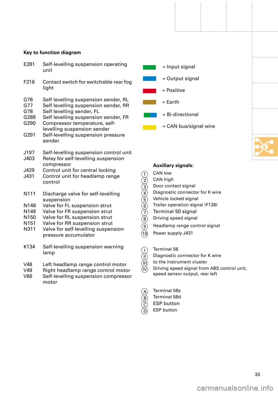
Key to function diagram
E281 Self-levelling suspension operating
unit
F216 Contact switch for switchable rear fog
light
G76 Self levelling suspension sender, RL
G77 Self levelling suspension sender, RR
G78 Self levelling sender, FL
G289 Self levelling suspension sender, FR
G290 Compressor temperature, self-
levelling suspension sender
G291 Self-levelling suspension pressure
sender
J197 Self-levelling suspension control unit
J403 Relay for self-levelling suspension
compressor
J429 Control unit for central locking
J431 Control unit for headlamp range
control
N111 Discharge valve for self-levelling
suspension
N148 Valve for FL suspension strut
N149 Valve for FR suspension strut
N150 Valve for RL suspension strut
N151 Valve for RR suspension strut
N311 Valve for self-levelling suspension
pressure accumulator
K134 Self-levelling suspension warning
lamp
V48 Left headlamp range control motor
V49 Right headlamp range control motor
V66 Self-levelling suspension compressor
motor= Input signal
= Output signal
= Positive
= Earth
= Bi-directional
= CAN bus/signal wire
Auxiliary signals:
CAN low
CAN high
Door contact signal
Diagnostic connector for K wire
Vehicle locked signal
Trailer operation signal (F126)
Terminal 50 signal
Driving speed signal
Terminal 56
Diagnostic connector for K wire
to the instrument cluster
Driving speed signal from ABS control unit,
speed sensor output, rear left
1
2
3
4
5
6
7
8
I
II
III
IV
Terminal 58s
Terminal 58d
ESP button
ESP button
A
B
C
DHeadlamp range control signal
9
Power supply J431
10
Page 41 of 44

41
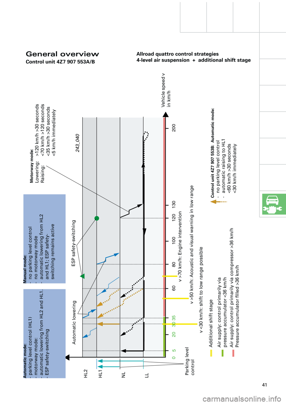
Allroad quattro control strategies
4-level air suspension + additional shift stage
0203580 60
5100 120 130 200
30
General overview
Control unit 4Z7 907 553A/B
ESP safety-switching
Automatic lowering
Parking level
control
v >70 km/h: Engine intervention
v >50 km/h: Acoustic and visual warning in low range
Air supply: control primarily via
pressure accumulator <36 km/hVehicle speed v
in km/h
v <30 km/h: shift to low range possible
Additional shift stage
Air supply: control primarily via compressor >36 km/h
Pressure accumulator filled >36 km/h
Motorway mode:Lowering: >120 km/h >30 seconds
Raising: <70 km/h >120 seconds
<35 km/h >30 seconds
<5 km/h immediately
Manual mode:- no parking level control
- no motorway mode
- automatic lowering from HL2
and HL1; ESP safety-
switching remains active
Automatic mode:- parking level control (HL1)
- motorway mode:
- automatic lowering from HL2 and HL1.
- ESP safety-switching
LL NL HL1 HL2243_040
Control unit 4Z7 907 553B: Automatic mode:- no parking level control
- automatic raising to HL1
<60 km/h >30 seconds
<30 km/h immediately