AUDI A8 1997 D2 / 1.G AEB Engine Motronic MFI And Ignition System
Manufacturer: AUDI, Model Year: 1997,
Model line: A8,
Model: AUDI A8 1997 D2 / 1.G
Pages: 135, PDF Size: 0.71 MB
AUDI A8 1997 D2 / 1.G AEB Engine Motronic MFI And Ignition System
A8 1997 D2 / 1.G
AUDI
AUDI
https://www.carmanualsonline.info/img/6/999/w960_999-0.png
AUDI A8 1997 D2 / 1.G AEB Engine Motronic MFI And Ignition System
Trending: coolant temperature, air filter, OBD port, fuel cap, battery, diagram, fuel filter
Page 101 of 135
Specified value: max. 1.5
Pa
ge 101 of 135 Motronic Multi
port Fuel In
jection
(MFI
) and i
gnition s
ystem
11/19/2002 htt
p://127.0.0.1:8080/audi/servlet/Dis
play?action=Goto&t
yp
e=re
pair&id=AUDI.B5.FU02.24.1
Page 102 of 135
24-76
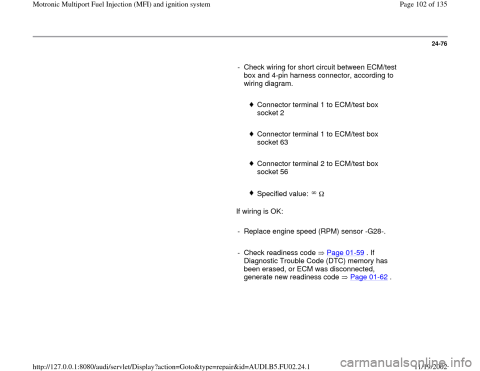
- Check wiring for short circuit between ECM/test
box and 4-pin harness connector, according to
wiring diagram.
Connector terminal 1 to ECM/test box
socket 2
Connector terminal 1 to ECM/test box
socket 63
Connector terminal 2 to ECM/test box
socket 56
Specified value:
If wiring is OK:
- Replace engine speed (RPM) sensor -G28-.
- Check readiness code Page 01
-59
. If
Diagnostic Trouble Code (DTC) memory has
been erased, or ECM was disconnected,
generate new readiness code Page 01
-62
.
Pa
ge 102 of 135 Motronic Multi
port Fuel In
jection
(MFI
) and i
gnition s
ystem
11/19/2002 htt
p://127.0.0.1:8080/audi/servlet/Dis
play?action=Goto&t
yp
e=re
pair&id=AUDI.B5.FU02.24.1
Page 103 of 135
24-77
Voltage supply to Engine Control
Module (ECM)
Required special tools and test equipment
VAG 1551 or VAG 1552 Scan Tool (ST) with
VAG 1551/3 adapter cable
VAG 1598/22 test box
Multimeter US 1119 (Fluke 83 or equivalent)
VW 1594 connector test kit
Wiring diagram
Checking
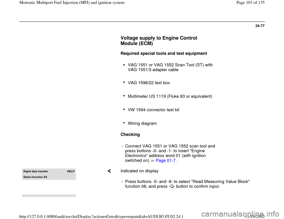
- Connect VAG 1551 or VAG 1552 scan tool and
press buttons -0- and -1- to insert "Engine
Electronics" address word 01 (with ignition
switched on) Page 01
-7 .
Rapid data transfer
HELP
Select function XX
Indicated on display
- Press buttons -0- and -8- to select "Read Measuring Value Block"
function 08, and press -Q- button to confirm input.
Pa
ge 103 of 135 Motronic Multi
port Fuel In
jection
(MFI
) and i
gnition s
ystem
11/19/2002 htt
p://127.0.0.1:8080/audi/servlet/Dis
play?action=Goto&t
yp
e=re
pair&id=AUDI.B5.FU02.24.1
Page 104 of 135
Read Measurin
g Value Block
HELP
Input display group number XXX
Indicated on display
- Press buttons -0-, -0- and -4- to input display group number 4, and
press -Q- button to confirm input.
Read Measuring Value Block 4 1 2 3 4
Indicated on display (1-4 = display fields)
Pa
ge 104 of 135 Motronic Multi
port Fuel In
jection
(MFI
) and i
gnition s
ystem
11/19/2002 htt
p://127.0.0.1:8080/audi/servlet/Dis
play?action=Goto&t
yp
e=re
pair&id=AUDI.B5.FU02.24.1
Page 105 of 135
24-78
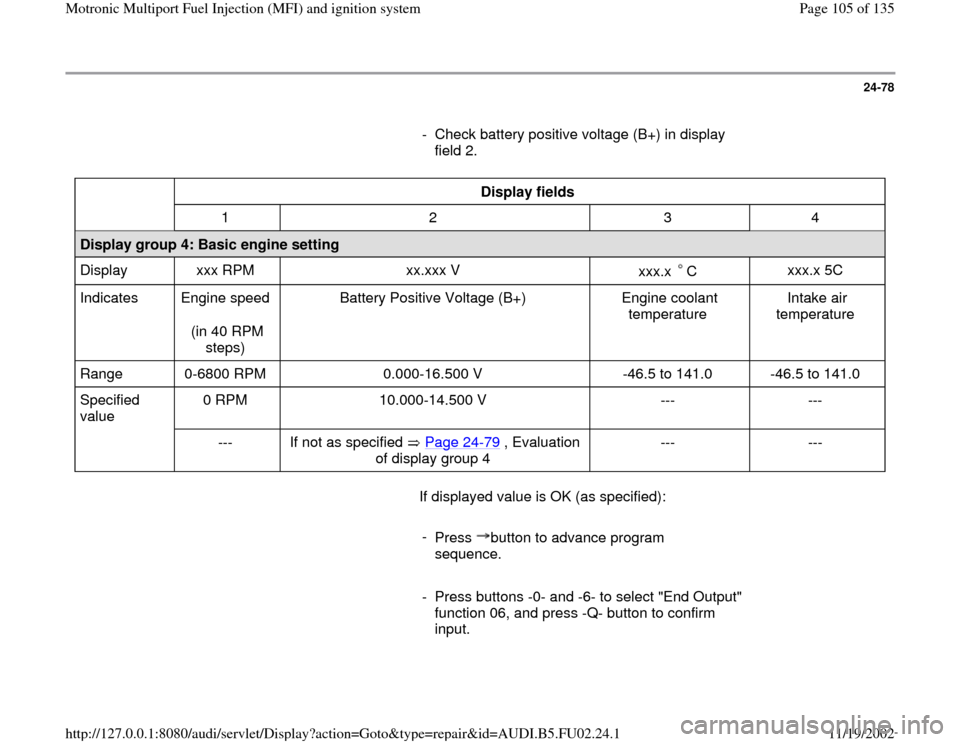
- Check battery positive voltage (B+) in display
field 2.
Display fields
1 2 3 4
Display group 4: Basic engine setting
Display xxx RPM xx.xxx V
xxx.x C
xxx.x 5C
Indicates Engine speed
(in 40 RPM
steps) Battery Positive Voltage (B+) Engine coolant
temperature Intake air
temperature
Range 0-6800 RPM 0.000-16.500 V -46.5 to 141.0 -46.5 to 141.0
Specified
value 0 RPM 10.000-14.500 V --- ---
--- If not as specified Page 24
-79
, Evaluation
of display group 4
--- ---
If displayed value is OK (as specified):
-
Press button to advance program
sequence.
- Press buttons -0- and -6- to select "End Output"
function 06, and press -Q- button to confirm
input.
Pa
ge 105 of 135 Motronic Multi
port Fuel In
jection
(MFI
) and i
gnition s
ystem
11/19/2002 htt
p://127.0.0.1:8080/audi/servlet/Dis
play?action=Goto&t
yp
e=re
pair&id=AUDI.B5.FU02.24.1
Page 106 of 135
24-79
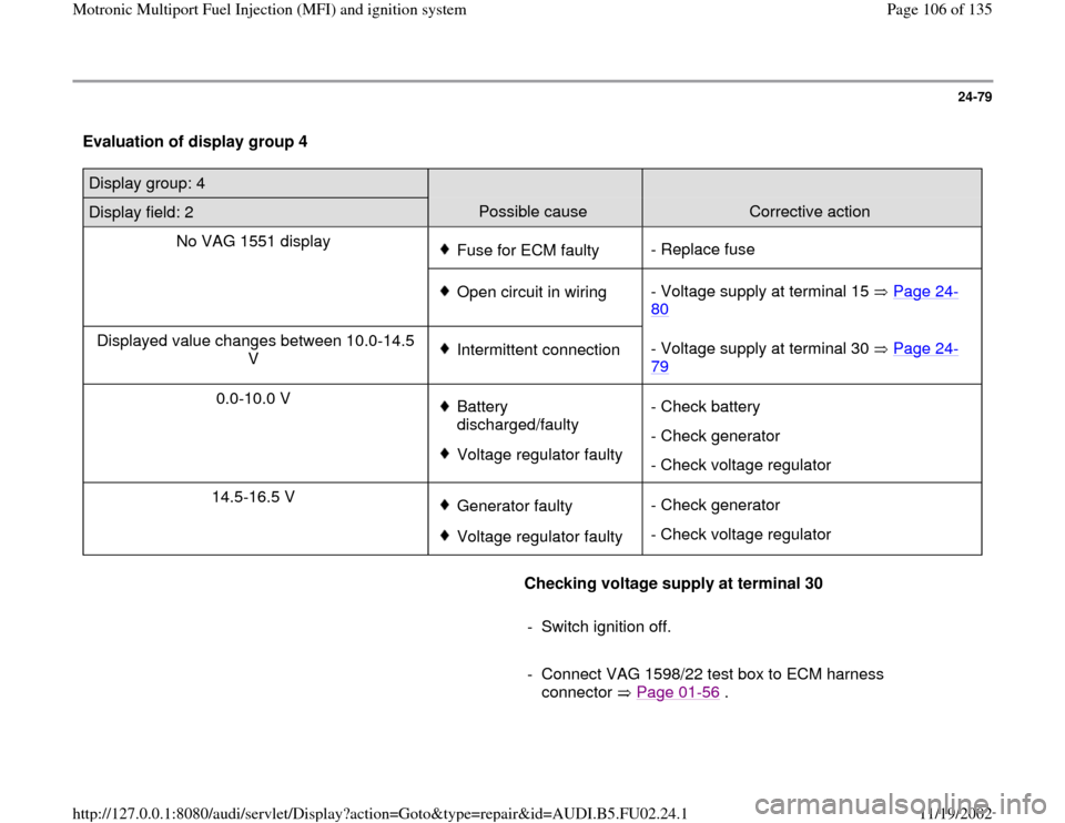
Evaluation of display group 4 Display group: 4
Display field: 2
Possible cause
Corrective action
No VAG 1551 display
Fuse for ECM faulty- Replace fuse
Open circuit in wiring- Voltage supply at terminal 15 Page 24
-
80
Displayed value changes between 10.0-14.5
V
Intermittent connection - Voltage supply at terminal 30 Page 24
-
79
0.0-10.0 V
Battery
discharged/faulty Voltage regulator faulty - Check battery
- Check generator
- Check voltage regulator
14.5-16.5 V Generator faultyVoltage regulator faulty - Check generator
- Check voltage regulator
Checking voltage supply at terminal 30
- Switch ignition off.
- Connect VAG 1598/22 test box to ECM harness
connector Page 01
-56
.
Pa
ge 106 of 135 Motronic Multi
port Fuel In
jection
(MFI
) and i
gnition s
ystem
11/19/2002 htt
p://127.0.0.1:8080/audi/servlet/Dis
play?action=Goto&t
yp
e=re
pair&id=AUDI.B5.FU02.24.1
Page 107 of 135
- Connect multimeter US 1119 (Fluke 83 or
equivalent) between ECM/test box sockets 2
(Ground) and 3 (B+), using adapter cables from
VW 1594 connector test kit.
Specified value: 10-14.5 volts
Pa
ge 107 of 135 Motronic Multi
port Fuel In
jection
(MFI
) and i
gnition s
ystem
11/19/2002 htt
p://127.0.0.1:8080/audi/servlet/Dis
play?action=Goto&t
yp
e=re
pair&id=AUDI.B5.FU02.24.1
Page 108 of 135
24-80
If voltage is NOT OK:
- Check wiring according to applicable wiring
diagram.
Checking voltage supply at terminal 15
- Switch ignition off.
- Connect VAG 1598/22 test box to ECM harness
connector Page 01
-56
.
- Connect multimeter between ECM/test box
sockets 1 (B+) and 2 (Ground), using adapter
cables from VW 1594 connector test kit.
- Switch ignition on, and check voltage.
Specified value: 10-14.5 volts
If voltage is NOT OK:
- Check wiring according to applicable wiring
diagram.
-
Check readiness code Page 01
-59
. If
Diagnostic Trouble Code (DTC) memory has
been erased, or ECM was disconnected,
Pa
ge 108 of 135 Motronic Multi
port Fuel In
jection
(MFI
) and i
gnition s
ystem
11/19/2002 htt
p://127.0.0.1:8080/audi/servlet/Dis
play?action=Goto&t
yp
e=re
pair&id=AUDI.B5.FU02.24.1
Page 109 of 135
generate new readiness code Page 01
-62
.
Pa
ge 109 of 135 Motronic Multi
port Fuel In
jection
(MFI
) and i
gnition s
ystem
11/19/2002 htt
p://127.0.0.1:8080/audi/servlet/Dis
play?action=Goto&t
yp
e=re
pair&id=AUDI.B5.FU02.24.1
Page 110 of 135
24-81
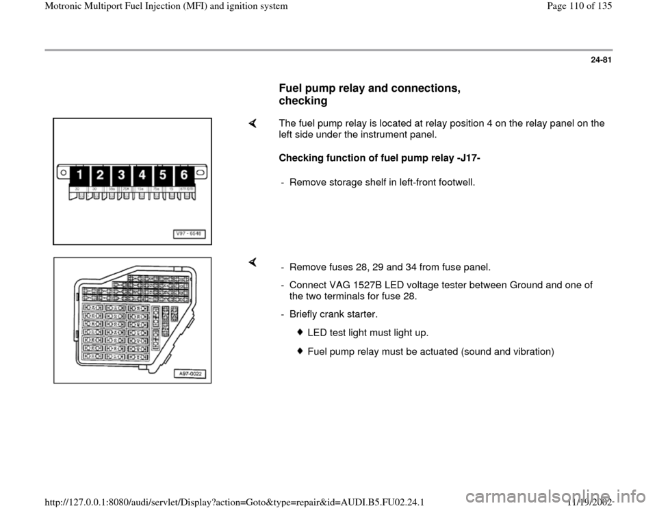
Fuel pump relay and connections,
checking
The fuel pump relay is located at relay position 4 on the relay panel on the
left side under the instrument panel.
Checking function of fuel pump relay -J17-
- Remove storage shelf in left-front footwell.
- Remove fuses 28, 29 and 34 from fuse panel.
- Connect VAG 1527B LED voltage tester between Ground and one of
the two terminals for fuse 28.
- Briefly crank starter.
LED test light must light up.
Fuel pump relay must be actuated (sound and vibration)
Pa
ge 110 of 135 Motronic Multi
port Fuel In
jection
(MFI
) and i
gnition s
ystem
11/19/2002 htt
p://127.0.0.1:8080/audi/servlet/Dis
play?action=Goto&t
yp
e=re
pair&id=AUDI.B5.FU02.24.1
Trending: fuse diagram, ESP, fuel, radiator, instrument panel, oil change, gas type

