check engine AUDI A8 1999 D2 / 1.G ATQ Engine Ignition System Checking Workshop Manual
[x] Cancel search | Manufacturer: AUDI, Model Year: 1999, Model line: A8, Model: AUDI A8 1999 D2 / 1.GPages: 65, PDF Size: 0.53 MB
Page 1 of 65
28-1
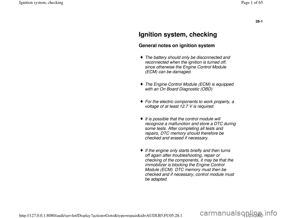
Ignition system, checking
General notes on ignition system
The battery should only be disconnected and
reconnected when the ignition is turned off,
since otherwise the Engine Control Module
(ECM) can be damaged.
The Engine Control Module (ECM) is equipped
with an On Board Diagnostic (OBD)
For the electric components to work properly, a
voltage of at least 12.7 V is required.
It is possible that the control module will
recognize a malfunction and store a DTC during
some tests. After completing all tests and
repairs, DTC memory should therefore be
checked and erased if necessary.
If the engine only starts briefly and then turns
off again after troubleshooting, repair or
checking of the components, it may be that the
immobilizer is blocking the Engine Control
Module (ECM). DTC memory must then be
checked and if necessary, control module must
be adapted.
Pa
ge 1 of 65 I
gnition s
ystem, checkin
g
11/23/2002 htt
p://127.0.0.1:8080/audi/servlet/Dis
play?action=Goto&t
yp
e=re
pair&id=AUDI.B5.FU05.28.1
Page 2 of 65
28-2
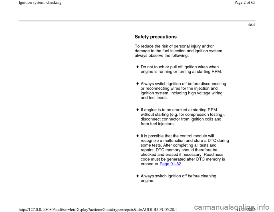
Safety precautions
To reduce the risk of personal injury and/or
damage to the fuel injection and ignition system,
always observe the following:
Do not touch or pull off ignition wires when
engine is running or turning at starting RPM.
Always switch ignition off before disconnecting
or reconnecting wires for the injection and
ignition system, including high voltage wiring
and test leads.
If engine is to be cranked at starting RPM
without starting (e.g. for compression testing),
disconnect connector from ignition coils and
from fuel injectors.
It is possible that the control module will
recognize a malfunction and store a DTC during
some tests. After completing all tests and
repairs, DTC memory should therefore be
checked and erased if necessary. Readiness
code must be generated after DTC memory is
erased Page 01
-82
.
Always switch ignition off before cleaning
engine.
Pa
ge 2 of 65 I
gnition s
ystem, checkin
g
11/23/2002 htt
p://127.0.0.1:8080/audi/servlet/Dis
play?action=Goto&t
yp
e=re
pair&id=AUDI.B5.FU05.28.1
Page 3 of 65
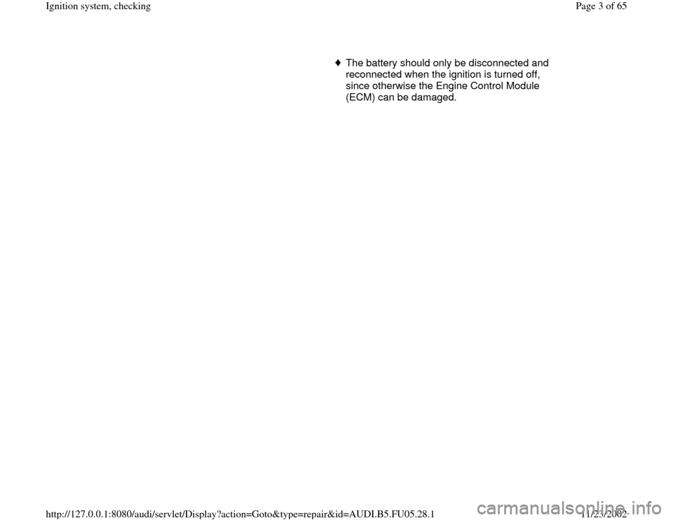
The battery should only be disconnected and
reconnected when the ignition is turned off,
since otherwise the Engine Control Module
(ECM) can be damaged.
Pa
ge 3 of 65 I
gnition s
ystem, checkin
g
11/23/2002 htt
p://127.0.0.1:8080/audi/servlet/Dis
play?action=Goto&t
yp
e=re
pair&id=AUDI.B5.FU05.28.1
Page 4 of 65
28-3
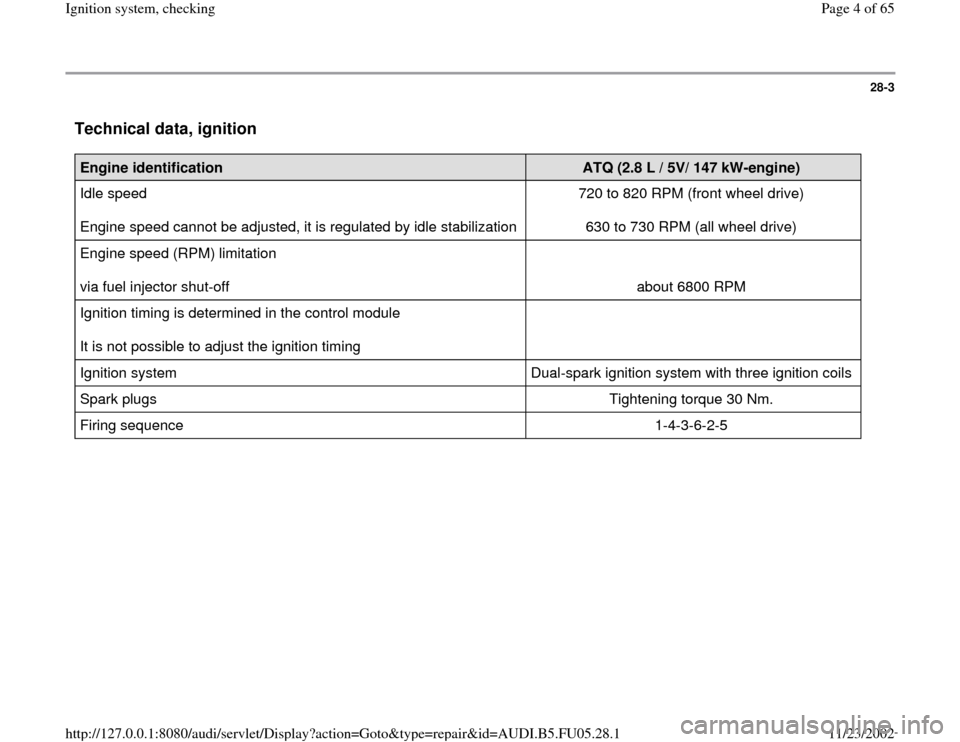
Technical data, ignition
Engine identification
ATQ (2.8 L / 5V/ 147 kW-engine)
Idle speed
Engine speed cannot be adjusted, it is regulated by idle stabilization 720 to 820 RPM (front wheel drive)
630 to 730 RPM (all wheel drive)
Engine speed (RPM) limitation
via fuel injector shut-off
about 6800 RPM
Ignition timing is determined in the control module
It is not possible to adjust the ignition timing
Ignition system Dual-spark ignition system with three ignition coils
Spark plugs Tightening torque 30 Nm.
Firing sequence 1-4-3-6-2-5
Pa
ge 4 of 65 I
gnition s
ystem, checkin
g
11/23/2002 htt
p://127.0.0.1:8080/audi/servlet/Dis
play?action=Goto&t
yp
e=re
pair&id=AUDI.B5.FU05.28.1
Page 13 of 65
28-11
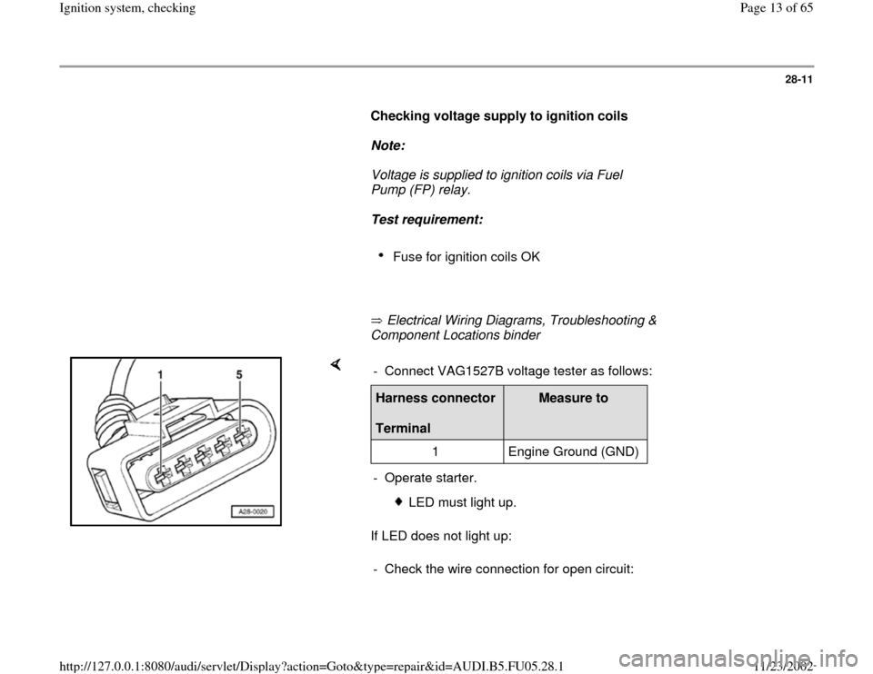
Checking voltage supply to ignition coils
Note:
Voltage is supplied to ignition coils via Fuel
Pump (FP) relay.
Test requirement:
Fuse for ignition coils OK
Electrical Wiring Diagrams, Troubleshooting &
Component Locations binder
If LED does not light up: - Connect VAG1527B voltage tester as follows:Harness connector
Terminal
Measure to
1 Engine Ground (GND)
- Operate starter.
LED must light up.
- Check the wire connection for open circuit:
Pa
ge 13 of 65 I
gnition s
ystem, checkin
g
11/23/2002 htt
p://127.0.0.1:8080/audi/servlet/Dis
play?action=Goto&t
yp
e=re
pair&id=AUDI.B5.FU05.28.1
Page 15 of 65
28-12
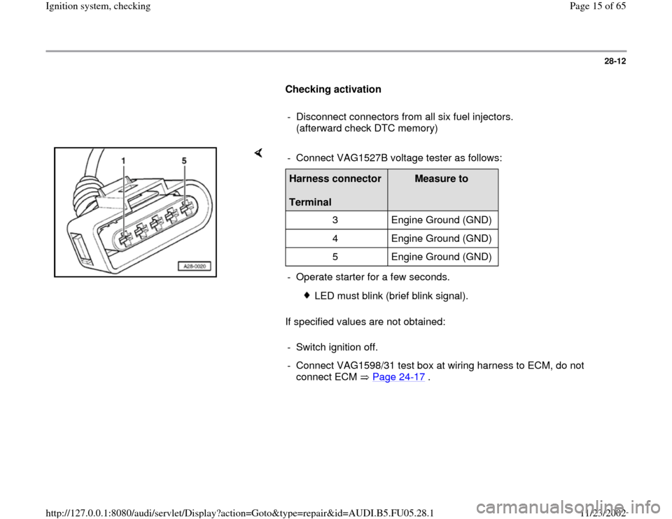
Checking activation
- Disconnect connectors from all six fuel injectors.
(afterward check DTC memory)
If specified values are not obtained: - Connect VAG1527B voltage tester as follows:Harness connector
Terminal
Measure to
3 Engine Ground (GND)
4 Engine Ground (GND)
5 Engine Ground (GND)
- Operate starter for a few seconds.
LED must blink (brief blink signal).
- Switch ignition off.
- Connect VAG1598/31 test box at wiring harness to ECM, do not
connect ECM Page 24
-17
.
Pa
ge 15 of 65 I
gnition s
ystem, checkin
g
11/23/2002 htt
p://127.0.0.1:8080/audi/servlet/Dis
play?action=Goto&t
yp
e=re
pair&id=AUDI.B5.FU05.28.1
Page 16 of 65
28-13
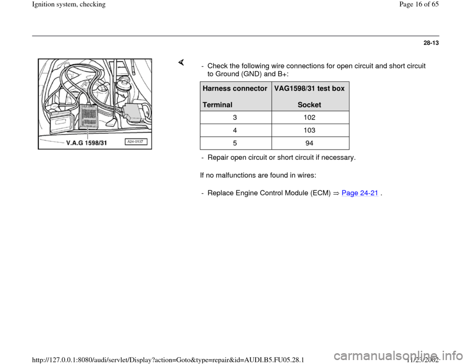
If no malfunctions are found in wires: - Check the following wire connections for open circuit and short circuit
to Ground (GND) and B+: Harness connector
Terminal
VAG1598/31 test box
Socket
3 102
4 103
5 94
- Repair open circuit or short circuit if necessary.
- Replace Engine Control Module (ECM) Page 24
-21
.
Pa
ge 16 of 65 I
gnition s
ystem, checkin
g
11/23/2002 htt
p://127.0.0.1:8080/audi/servlet/Dis
play?action=Goto&t
yp
e=re
pair&id=AUDI.B5.FU05.28.1
Page 18 of 65
28-15
Component location Overview of Component
Locations, page Page 24
-5
Test sequence
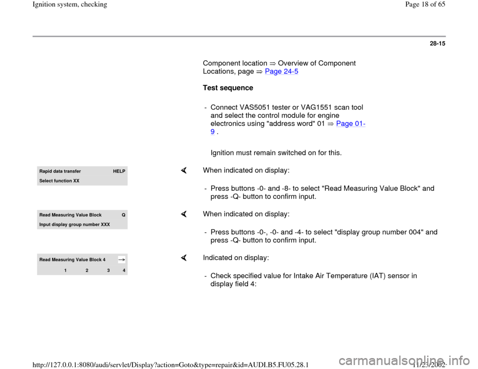
- Connect VAS5051 tester or VAG1551 scan tool
and select the control module for engine
electronics using "address word" 01 Page 01
-
9 .
Ignition must remain switched on for this.Rapid data transfer
HELP
Select function XX
When indicated on display:
- Press buttons -0- and -8- to select "Read Measuring Value Block" and
press -Q- button to confirm input.
Read Measurin
g Value Block
Q
Input display group number XXX
When indicated on display:
- Press buttons -0-, -0- and -4- to select "display group number 004" and
press -Q- button to confirm input.
Read Measuring Value Block 4
1
2
3
4
Indicated on display:
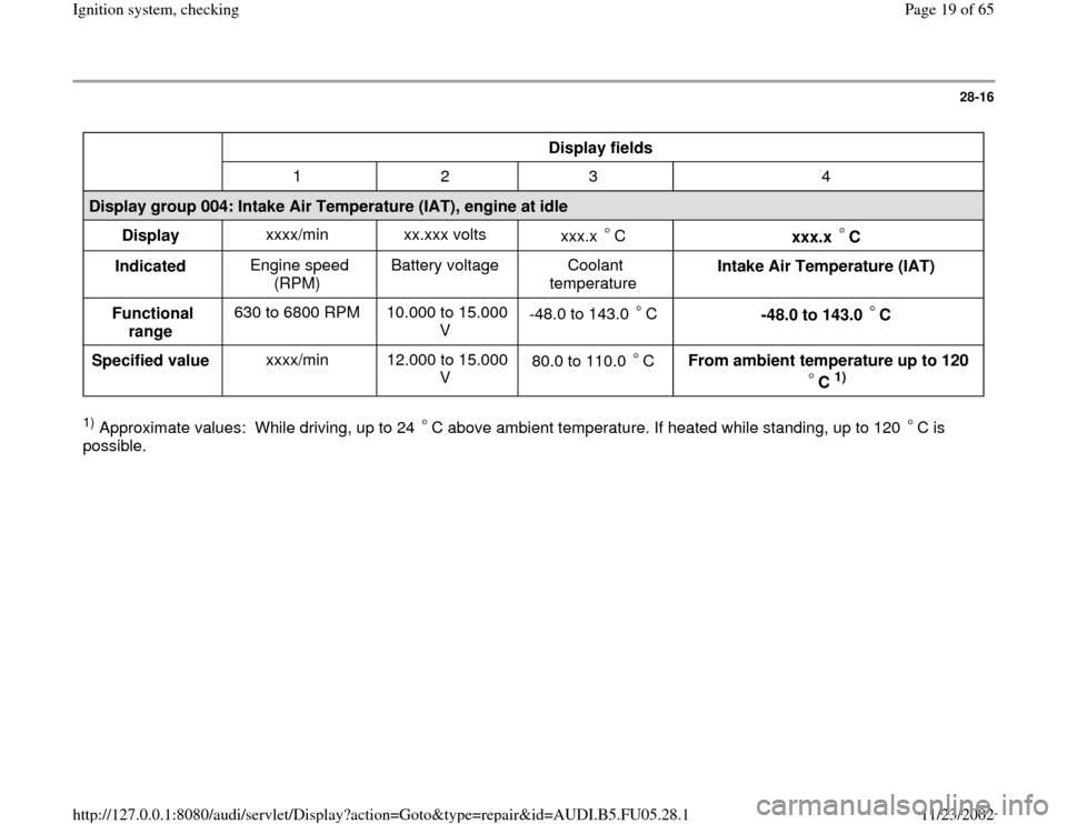
- Check specified value for Intake Air Temperature (IAT) sensor in
display field 4:
Pa
ge 18 of 65 I
gnition s
ystem, checkin
g
11/23/2002 htt
p://127.0.0.1:8080/audi/servlet/Dis
play?action=Goto&t
yp
e=re
pair&id=AUDI.B5.FU05.28.1
Page 19 of 65
28-16
Display fields
1 2 3 4
Display group 004: Intake Air Temperature (IAT), engine at idle
Display xxxx/min xx.xxx volts
xxx.x C
xxx.x C
Indicated Engine speed
(RPM) Battery voltage Coolant
temperature Intake Air Temperature (IAT)
Functional
range 630 to 6800 RPM 10.000 to 15.000
V -48.0 to 143.0 C
-48.0 to 143.0 C
Specified value xxxx/min 12.000 to 15.000
V 80.0 to 110.0 C
From ambient temperature up to 120
C
1)
1) Approximate values: While driving, up to 24 C above ambient temperature. If heated while standing, up to 120 C is
possible.
Pa
ge 19 of 65 I
gnition s
ystem, checkin
g
11/23/2002 htt
p://127.0.0.1:8080/audi/servlet/Dis
play?action=Goto&t
yp
e=re
pair&id=AUDI.B5.FU05.28.1
Page 22 of 65
28-19
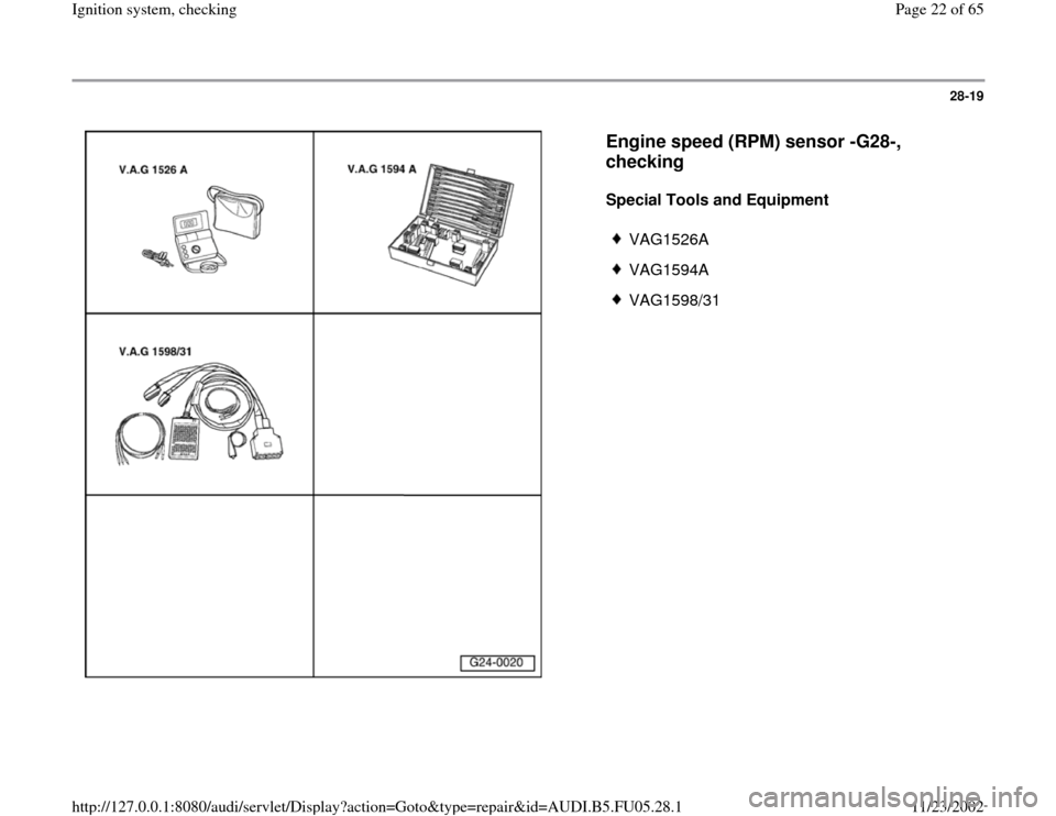
Engine speed (RPM) sensor -G28-,
checking
Special Tools and Equipment
VAG1526A
VAG1594A
VAG1598/31
Pa
ge 22 of 65 I
gnition s
ystem, checkin
g
11/23/2002 htt
p://127.0.0.1:8080/audi/servlet/Dis
play?action=Goto&t
yp
e=re
pair&id=AUDI.B5.FU05.28.1