light AUDI A8 2003 D3 / 2.G Technical Features Manual
[x] Cancel search | Manufacturer: AUDI, Model Year: 2003, Model line: A8, Model: AUDI A8 2003 D3 / 2.GPages: 96, PDF Size: 5.51 MB
Page 3 of 96
Downloaded from www.Manualslib.com manuals search engine 3
Attention
NoteNew
Contents
Page
Introduction . . . . . . . . . . . . . . . . . . . . . . . . . . . . . . . . . . . . . . . . . . 4
Body . . . . . . . . . . . . . . . . . . . . . . . . . . . . . . . . . . . . . . . . . . . . . . . . 6
Passenger Protection
System layout . . . . . . . . . . . . . . . . . . . . . . . . . . . . . . . . . . . . . . . . . . . . . . . . 14
Block diagram . . . . . . . . . . . . . . . . . . . . . . . . . . . . . . . . . . . . . . . . . . . . . . . . 16
Safety systems . . . . . . . . . . . . . . . . . . . . . . . . . . . . . . . . . . . . . . . . . . . . . . . 18
Engine, Mechanics
Technical data of V8 4.2 l 5V engine . . . . . . . . . . . . . . . . . . . . . . . . . . . . . . 24
Technical data of V8 3.7 l 5V engine . . . . . . . . . . . . . . . . . . . . . . . . . . . . . . 25
System layout . . . . . . . . . . . . . . . . . . . . . . . . . . . . . . . . . . . . . . . . . . . . . . . . 30
Electrohydraulic torque reaction support . . . . . . . . . . . . . . . . . . . . . . . . . 32
Exhaust system . . . . . . . . . . . . . . . . . . . . . . . . . . . . . . . . . . . . . . . . . . . . . . . 33
Fuel tank . . . . . . . . . . . . . . . . . . . . . . . . . . . . . . . . . . . . . . . . . . . . . . . . . . . . 34
Automatically controlled starting . . . . . . . . . . . . . . . . . . . . . . . . . . . . . . . . 41
Gearbox . . . . . . . . . . . . . . . . . . . . . . . . . . . . . . . . . . . . . . . . . . . . 45
Running Gear
Front axle . . . . . . . . . . . . . . . . . . . . . . . . . . . . . . . . . . . . . . . . . . . . . . . . . . . 49
Rear axle . . . . . . . . . . . . . . . . . . . . . . . . . . . . . . . . . . . . . . . . . . . . . . . . . . . . 50
4-level air suspension . . . . . . . . . . . . . . . . . . . . . . . . . . . . . . . . . . . . . . . . . 51
System layout . . . . . . . . . . . . . . . . . . . . . . . . . . . . . . . . . . . . . . . . . . . . . . . . 52
Electric parking brake . . . . . . . . . . . . . . . . . . . . . . . . . . . . . . . . . . . . . . . . . 53
Adaptive cruise control . . . . . . . . . . . . . . . . . . . . . . . . . . . . . . . . . . . . . . . . 54
Electrical System
Bus topology . . . . . . . . . . . . . . . . . . . . . . . . . . . . . . . . . . . . . . . . . . . . . . . . . 58
Convenience and security electronics . . . . . . . . . . . . . . . . . . . . . . . . . . . . 64
Lighting system . . . . . . . . . . . . . . . . . . . . . . . . . . . . . . . . . . . . . . . . . . . . . . 68
Heating/Air Conditioner
Design and operation. . . . . . . . . . . . . . . . . . . . . . . . . . . . . . . . . . . . . . . . . . 72
Operating principle . . . . . . . . . . . . . . . . . . . . . . . . . . . . . . . . . . . . . . . . . . . 74
Blower unit/air routing . . . . . . . . . . . . . . . . . . . . . . . . . . . . . . . . . . . . . . . . . 76
System layout . . . . . . . . . . . . . . . . . . . . . . . . . . . . . . . . . . . . . . . . . . . . . . . . 80
Block diagram for front air conditioner . . . . . . . . . . . . . . . . . . . . . . . . . . . 86
Block diagram for rear air conditioner . . . . . . . . . . . . . . . . . . . . . . . . . . . . 88
The Self Study Programme contains information on design
features and functions.
The Self Study Programme is not intended as a Workshop
Manual. Values given are only intended to help explain the
subject matter and relate to the software version applicable at
the time of SSP compilation.
Use should always be made of the latest technical publications
when performing maintenance and repair work.
Page 4 of 96
Downloaded from www.Manualslib.com manuals search engine 4
Introduction
The new Audi A8 is designed to replace its
predecessor of the same name which achieved
a total production figure of 105,092 since its
introduction in June 1994. This was the first
standard saloon with aluminium body and
epitomised a new philosophy in the luxury
vehicle sector.
The weight-saving Audi Space Frame ASF
represented a major breakthrough in terms of
enhanced vehicle dynamics, whilst at the same
time solving the problem of increasing weight.
Introduction
This body concept was further perfected in
the Audi A2 and the design of the Audi A8 ´03
reflects the experience gained from both
projects.
The aim when developing the Audi A8 ´03 was
not merely to surpass its predecessor in
terms of technical features and details.
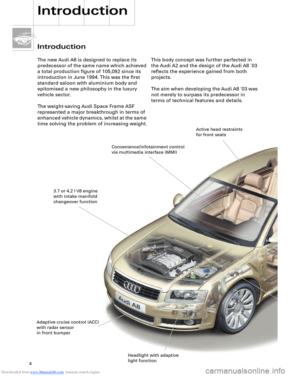
Convenience/infotainment control
via multimedia interface (MMI)
3.7 or 4.2 l V8 engine
with intake manifold
changeover function
Adaptive cruise control (ACC)
with radar sensor
in front bumper
Headlight with adaptive
light functionActive head restraints
for front seats
Page 5 of 96
Downloaded from www.Manualslib.com manuals search engine 5
SSP282_025
As the Audi flagship, the new Audi A8 is
intended to symbolise the product identity of
the next Audi generation.An uncompromising sporty character, clear-
cut design, innovative technological systems
and the highest possible quality level
combine to provide an unforgettable driving
experience.
In other words:
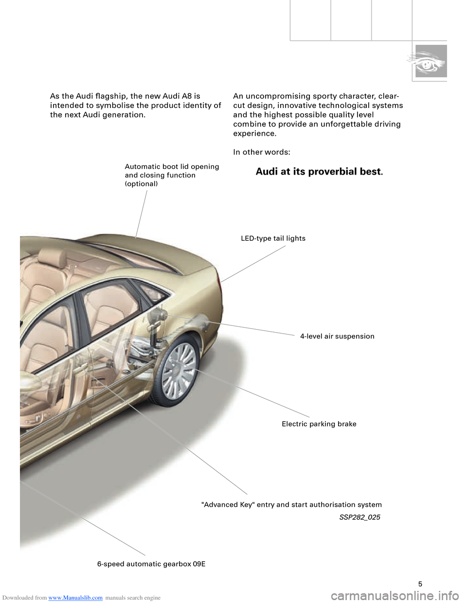
Audi at its proverbial best.Automatic boot lid opening
and closing function
(optional)
LED-type tail lights
4-level air suspension
Electric parking brake
"Advanced Key" entry and start authorisation system
6-speed automatic gearbox 09E
Page 7 of 96
Downloaded from www.Manualslib.com manuals search engine 7
Body
The Audi A8 ´03 sets new standards in its
class by combining lightweight construction
with outstanding stability. This is achieved
through the use of innovative Audi Space
Frame technology for the body design of the
Audi A8.
The technical progress reflected by the
unique body concept stems from the
consistent implementation of experience
gained from the aluminium Audi A8 and A2
models.
SSP282_027
Based on the findings obtained from these
vehicles, it was possible to further reduce the
number of body components and
significantly increase the level of automation
in the production process as compared to the
Audi A8 predecessor model.
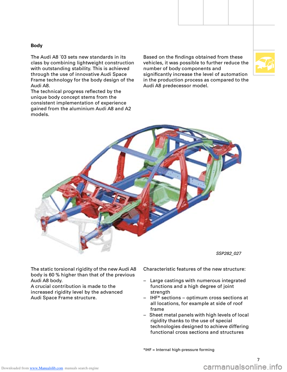
The static torsional rigidity of the new Audi A8
body is 60 % higher than that of the previous
Audi A8 body.
A crucial contribution is made to the
increased rigidity level by the advanced
Audi Space Frame structure.Characteristic features of the new structure:
– Large castings with numerous integrated
functions and a high degree of joint
strength
– IHF* sections – optimum cross sections at
all locations, for example at side of roof
frame
– Sheet metal panels with high levels of local
rigidity thanks to the use of special
technologies designed to achieve differing
functional cross sections and structures
*IHF = Internal high-pressure forming
Page 12 of 96
Downloaded from www.Manualslib.com manuals search engine 12
Body
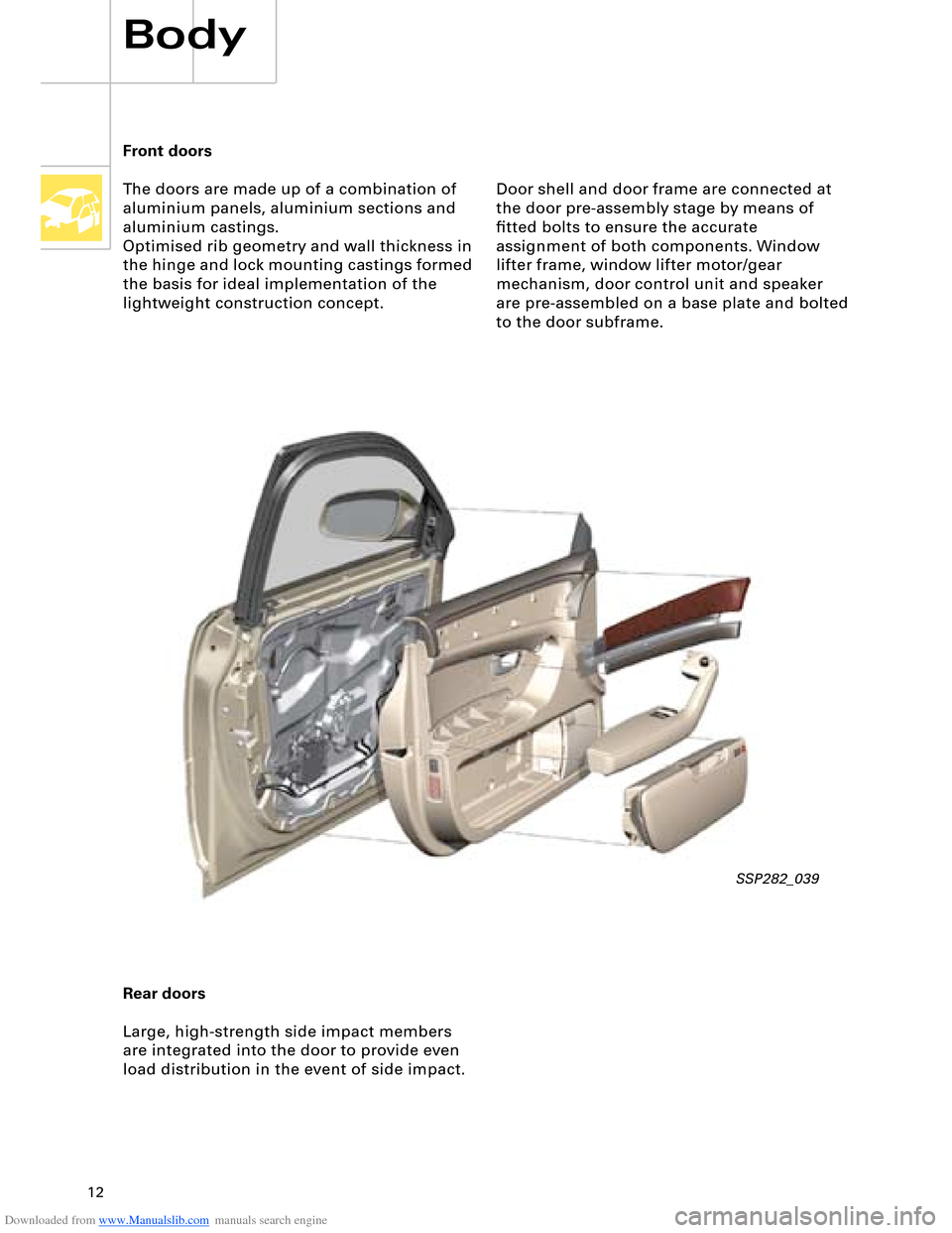
Front doors
The doors are made up of a combination of
aluminium panels, aluminium sections and
aluminium castings.
Optimised rib geometry and wall thickness in
the hinge and lock mounting castings formed
the basis for ideal implementation of the
lightweight construction concept.
Rear doors
Large, high-strength side impact members
are integrated into the door to provide even
load distribution in the event of side impact.
SSP282_039
Door shell and door frame are connected at
the door pre-assembly stage by means of
fitted bolts to ensure the accurate
assignment of both components. Window
lifter frame, window lifter motor/gear
mechanism, door control unit and speaker
are pre-assembled on a base plate and bolted
to the door subframe.
Page 20 of 96
Downloaded from www.Manualslib.com manuals search engine 20
Passenger Protection
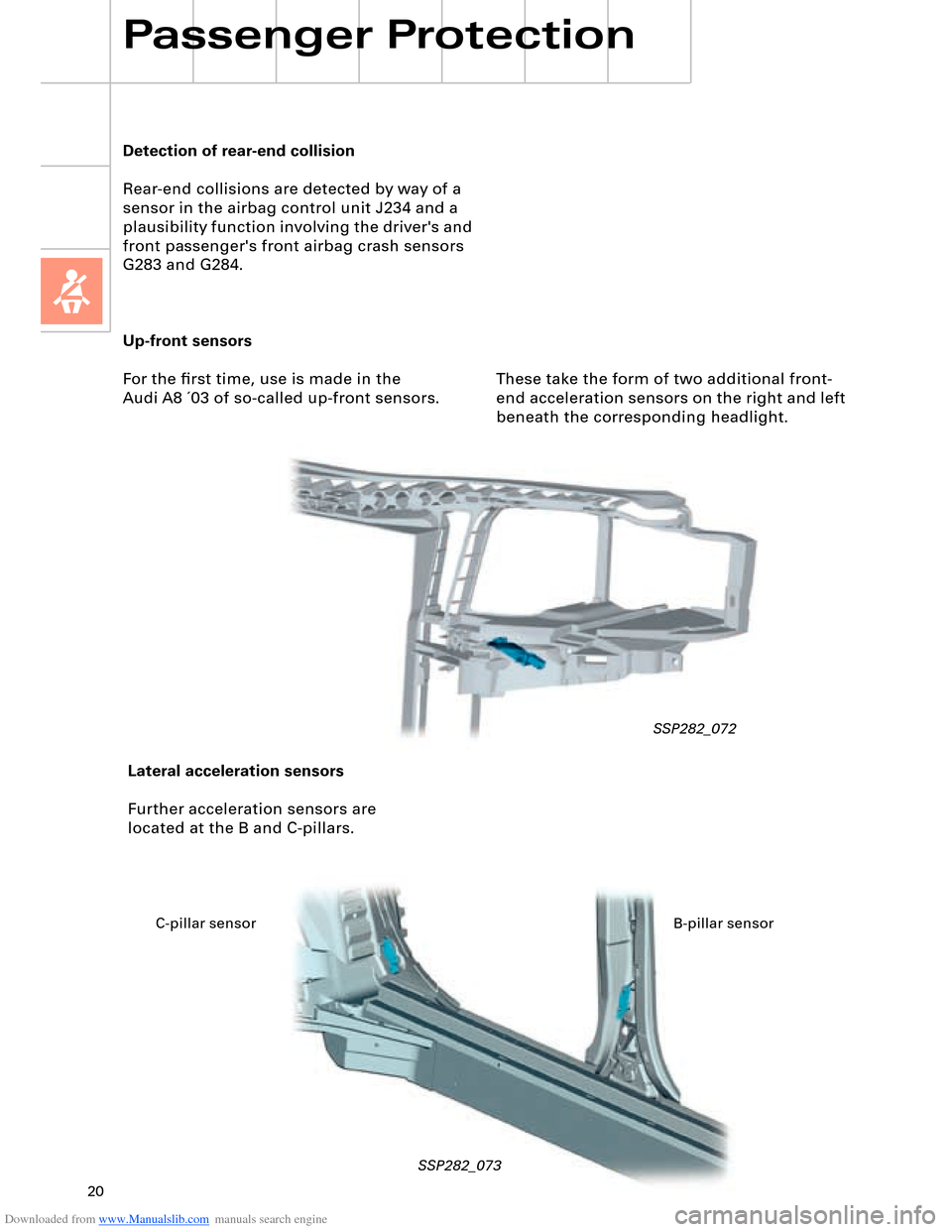
Up-front sensors
For the first time, use is made in the
Audi A8 ´03 of so-called up-front sensors.
SSP282_072
Lateral acceleration sensors
Further acceleration sensors are
located at the B and C-pillars.
SSP282_073
Detection of rear-end collision
Rear-end collisions are detected by way of a
sensor in the airbag control unit J234 and a
plausibility function involving the driver's and
front passenger's front airbag crash sensors
G283 and G284.
These take the form of two additional front-
end acceleration sensors on the right and left
beneath the corresponding headlight.
C-pillar sensor B-pillar sensor
Page 30 of 96
Downloaded from www.Manualslib.com manuals search engine 30
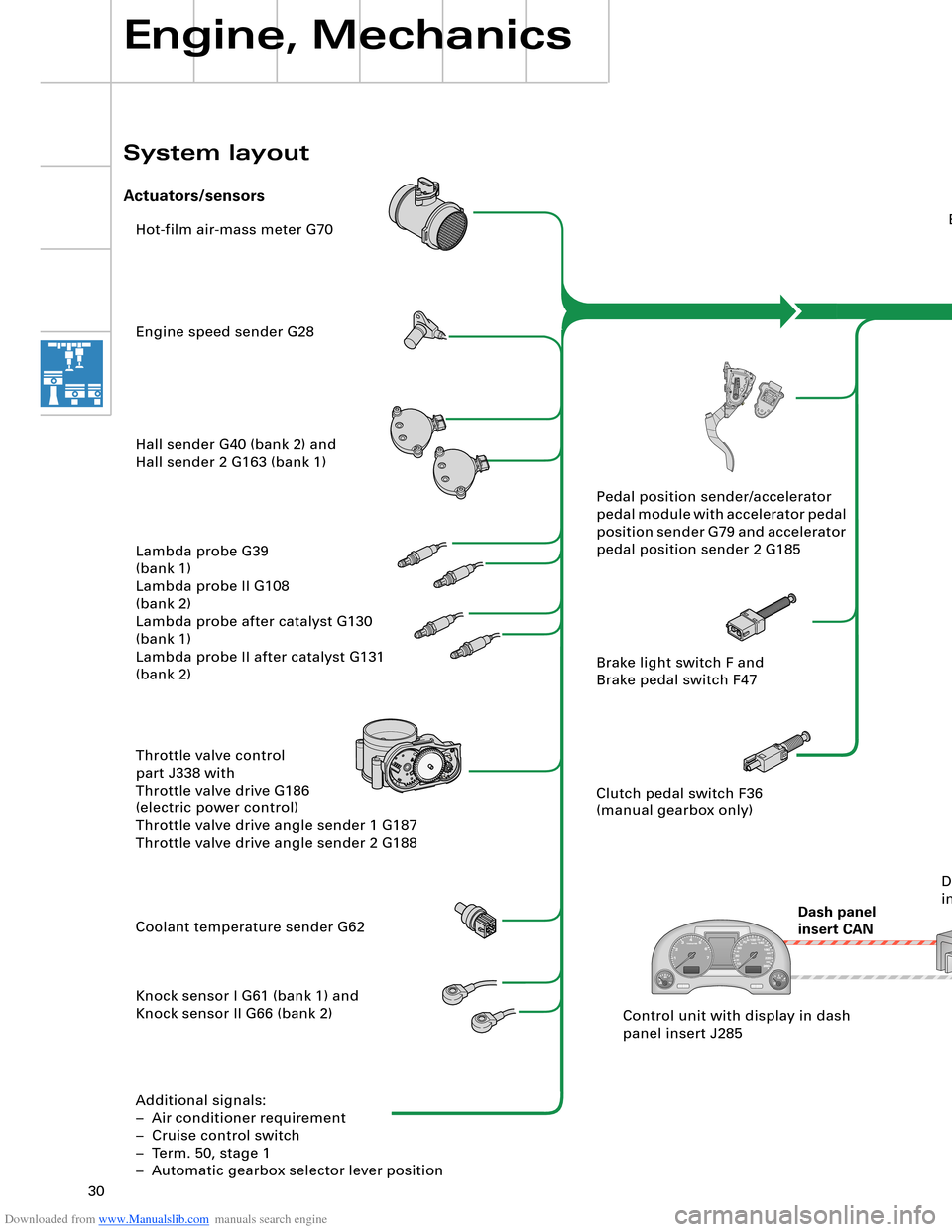
Hot-film air-mass meter G70
Engine speed sender G28
Hall sender G40 (bank 2) and
Hall sender 2 G163 (bank 1)
Lambda probe G39
(bank 1)
Lambda probe II G108
(bank 2)
Lambda probe after catalyst G130
(bank 1)
Lambda probe II after catalyst G131
(bank 2)
Throttle valve control
part J338 with
Throttle valve drive G186
(electric power control)
Throttle valve drive angle sender 1 G187
Throttle valve drive angle sender 2 G188
Coolant temperature sender G62
Knock sensor I G61 (bank 1) and
Knock sensor II G66 (bank 2)
Additional signals:
– Air conditioner requirement
– Cruise control switch
– Term. 50, stage 1
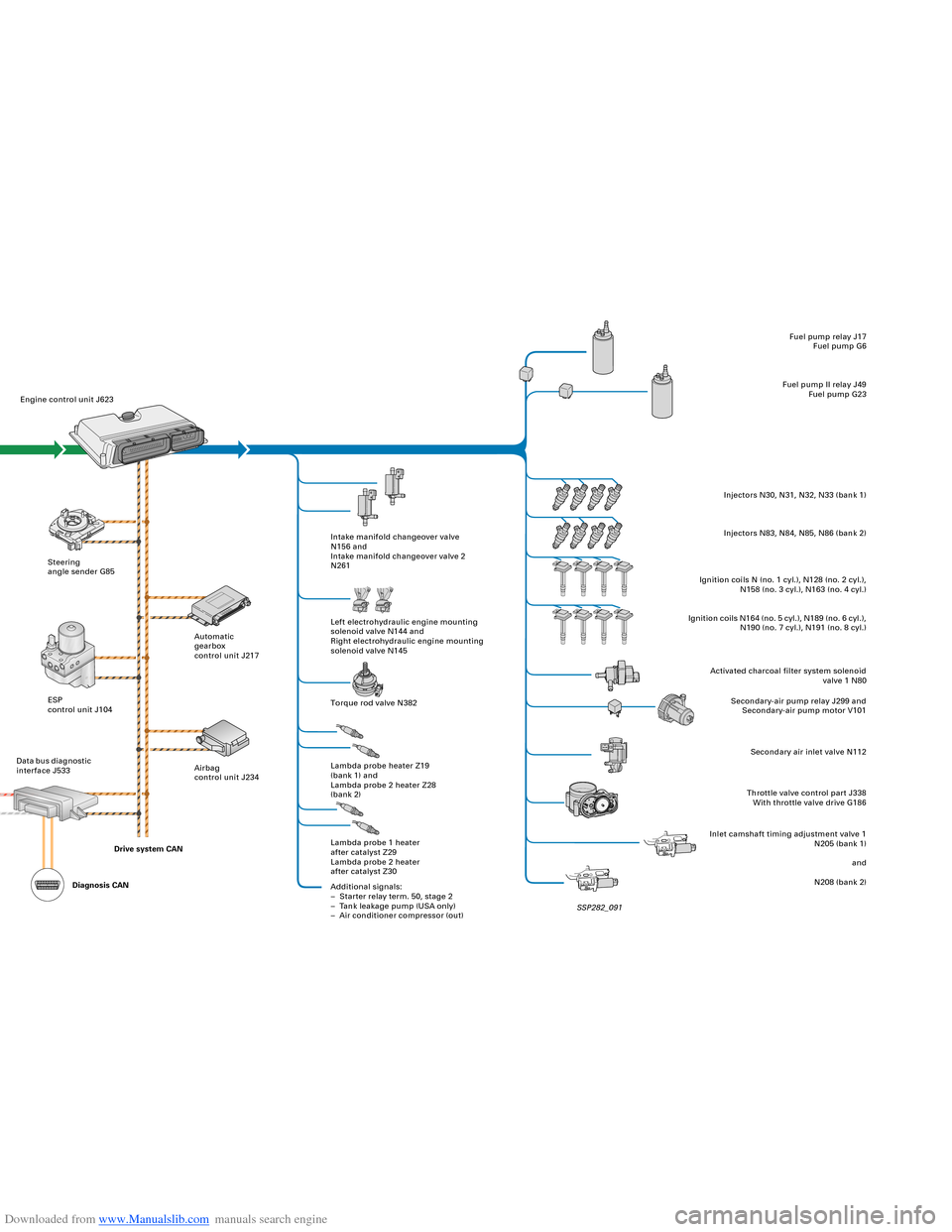
– Automatic gearbox selector lever positionEngine control unit J623
Steering
angle sender G85
ESP
control unit J104
Dash panel
insert CANAutomatic
gearbox
control unit J217
Airbag
control unit J234Intake manifold changeover valve
N156 and
Intake manifold changeover valve 2
N261
Left electrohydraulic engine mounting
solenoid valve N144 and
Right electrohydraulic engine mounting
solenoid valve N145
Torque rod valve N382
Lambda probe heater Z19
(bank 1) and
Lambda probe 2 heater Z28
(bank 2)
Lambda probe 1 heater
after catalyst Z29
Lambda probe 2 heater
after catalyst Z30
Additional signals:
– Starter relay term. 50, stage 2
– Tank leakage pump (USA only)
– Air conditioner compressor (out)Fuel pump relay J17
Fuel pump G6
Fuel pump II relay J49
Fuel pump G23
Injectors N30, N31, N32, N33 (bank 1)
Injectors N83, N84, N85, N86 (bank 2)
Ignition coils N (no. 1 cyl.), N128 (no. 2 cyl.),
N158 (no. 3 cyl.), N163 (no. 4 cyl.)
Ignition coils N164 (no. 5 cyl.), N189 (no. 6 cyl.),
N190 (no. 7 cyl.), N191 (no. 8 cyl.)
Activated charcoal filter system solenoid
valve 1 N80
Secondary-air pump relay J299 and
Secondary-air pump motor V101
Secondary air inlet valve N112
Throttle valve control part J338
With throttle valve drive G186
Inlet camshaft timing adjustment valve 1
N205 (bank 1)
and
N208 (bank 2) Pedal position sender/accelerator
pedal module with accelerator pedal
position sender G79 and accelerator
pedal position sender 2 G185
Brake light switch F and
Brake pedal switch F47
Clutch pedal switch F36
(manual gearbox only)
Control unit with display in dash
panel insert J285Data bus diagnostic
interface J533
Engine, Mechanics
System layout
Actuators/sensors
SSP282_091 Drive system CAN
Diagnosis CAN
Page 31 of 96
Downloaded from www.Manualslib.com manuals search engine 30
Hot-film air-mass meter G70
Engine speed sender G28
Hall sender G40 (bank 2) and
Hall sender 2 G163 (bank 1)
Lambda probe G39
(bank 1)
Lambda probe II G108
(bank 2)
Lambda probe after catalyst G130
(bank 1)
Lambda probe II after catalyst G131
(bank 2)
Throttle valve control
part J338 with
Throttle valve drive G186
(electric power control)
Throttle valve drive angle sender 1 G187
Throttle valve drive angle sender 2 G188
Coolant temperature sender G62
Knock sensor I G61 (bank 1) and
Knock sensor II G66 (bank 2)
Additional signals:
– Air conditioner requirement
– Cruise control switch
– Term. 50, stage 1
– Automatic gearbox selector lever positionEngine control unit J623
Steering
angle sender G85
ESP
control unit J104
Dash panel
insert CANAutomatic
gearbox
control unit J217
Airbag
control unit J234Intake manifold changeover valve
N156 and
Intake manifold changeover valve 2
N261
Left electrohydraulic engine mounting
solenoid valve N144 and
Right electrohydraulic engine mounting
solenoid valve N145
Torque rod valve N382
Lambda probe heater Z19
(bank 1) and
Lambda probe 2 heater Z28
(bank 2)
Lambda probe 1 heater
after catalyst Z29
Lambda probe 2 heater
after catalyst Z30
Additional signals:
– Starter relay term. 50, stage 2
– Tank leakage pump (USA only)
– Air conditioner compressor (out)Fuel pump relay J17
Fuel pump G6
Fuel pump II relay J49
Fuel pump G23
Injectors N30, N31, N32, N33 (bank 1)
Injectors N83, N84, N85, N86 (bank 2)
Ignition coils N (no. 1 cyl.), N128 (no. 2 cyl.),
N158 (no. 3 cyl.), N163 (no. 4 cyl.)
Ignition coils N164 (no. 5 cyl.), N189 (no. 6 cyl.),
N190 (no. 7 cyl.), N191 (no. 8 cyl.)
Activated charcoal filter system solenoid
valve 1 N80
Secondary-air pump relay J299 and
Secondary-air pump motor V101
Secondary air inlet valve N112
Throttle valve control part J338
With throttle valve drive G186
Inlet camshaft timing adjustment valve 1
N205 (bank 1)
and
N208 (bank 2) Pedal position sender/accelerator
pedal module with accelerator pedal
position sender G79 and accelerator
pedal position sender 2 G185
Brake light switch F and
Brake pedal switch F47
Clutch pedal switch F36
(manual gearbox only)
Control unit with display in dash
panel insert J285Data bus diagnostic
interface J533
Engine, Mechanics
System layout
Actuators/sensors
SSP282_091 Drive system CAN
Diagnosis CAN
Page 32 of 96
Downloaded from www.Manualslib.com manuals search engine 32
Electrohydraulic
torque reaction support
Engine, Mechanics
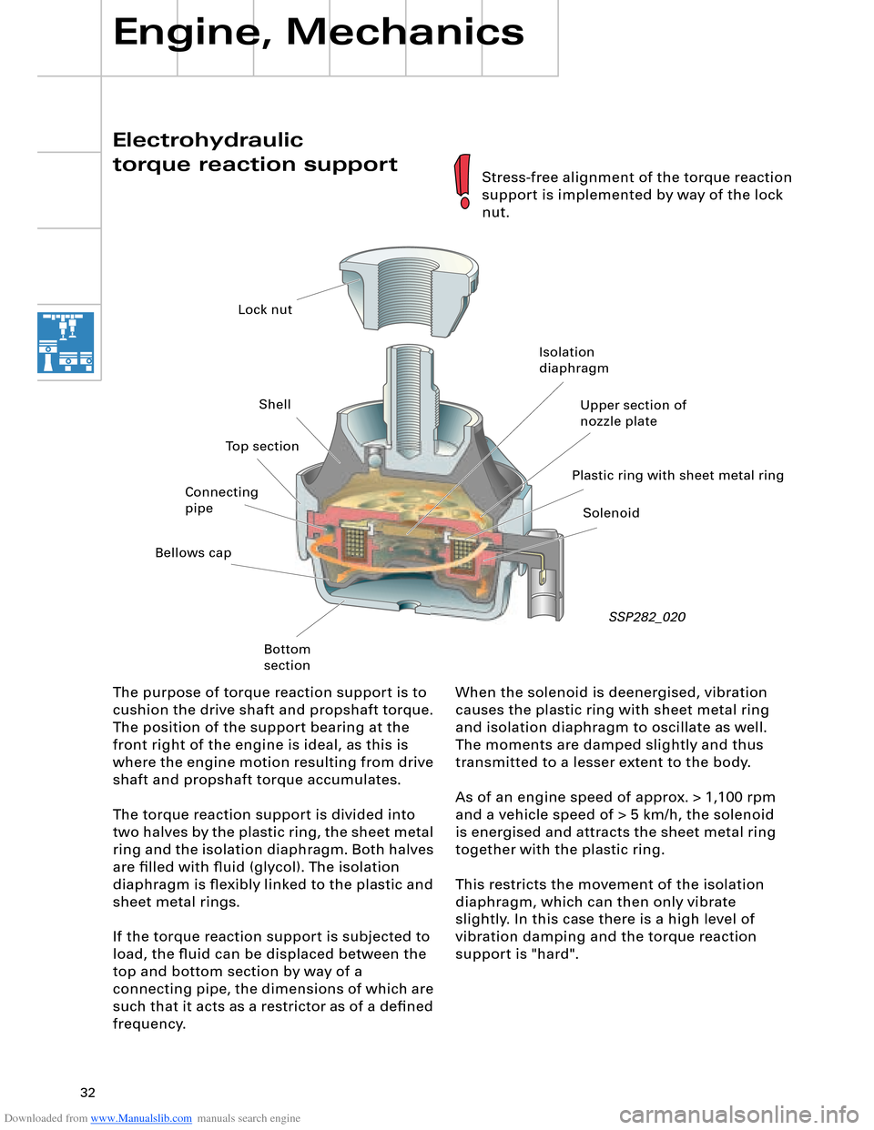
When the solenoid is deenergised, vibration
causes the plastic ring with sheet metal ring
and isolation diaphragm to oscillate as well.
The moments are damped slightly and thus
transmitted to a lesser extent to the body.
As of an engine speed of approx. > 1,100 rpm
and a vehicle speed of > 5 km/h, the solenoid
is energised and attracts the sheet metal ring
together with the plastic ring.
This restricts the movement of the isolation
diaphragm, which can then only vibrate
slightly. In this case there is a high level of
vibration damping and the torque reaction
support is "hard". The purpose of torque reaction support is to
cushion the drive shaft and propshaft torque.
The position of the support bearing at the
front right of the engine is ideal, as this is
where the engine motion resulting from drive
shaft and propshaft torque accumulates.
The torque reaction support is divided into
two halves by the plastic ring, the sheet metal
ring and the isolation diaphragm. Both halves
are filled with fluid (glycol). The isolation
diaphragm is flexibly linked to the plastic and
sheet metal rings.
If the torque reaction support is subjected to
load, the fluid can be displaced between the
top and bottom section by way of a
connecting pipe, the dimensions of which are
such that it acts as a restrictor as of a defined
frequency.
SSP282_020
Stress-free alignment of the torque reaction
support is implemented by way of the lock
nut.
Lock nut
Shell
Bellows cap
Bottom
sectionIsolation
diaphragm
Plastic ring with sheet metal ringUpper section of
nozzle plate
Solenoid Connecting
pipeTop section
Page 41 of 96
Downloaded from www.Manualslib.com manuals search engine 41
Automatically controlled
starting
The automatic start control is integrated into
the engine control unit.
A new feature is that starter control is no
longer implemented by way of the ignition/
starter switch D (switching of terminal 50),
but rather it is performed automatically by
the engine control unit.
Release for starter actuation is always
transmitted by the entry and start
authorisation control unit J518 to the engine
control unit J623.
In addition to general release by the
immobilizer, the following start release
conditions also have to be satisfied:
– Start signal from entry and start
authorisation switch E415 or entry and
start authorisation button E408
– Clutch pedal pressed, signal from clutch
pedal switch F194 (manual gearbox only)
– Selector lever position P or N (automatic
gearbox control unit J217)
– In the event of start signal via entry and
start authorisation button E408, brake
must be pressed (signal from brake light
switch F via separate interface)
As a safeguard, P/N signal or signal from
clutch pedal switch F194 must be applied
to the separate interfaces of the two
control units (J623 and J518).
Additional safeguard, as entry and start
authorisation button E408 can be
actuated by front passenger.
1
2 1
1
2