display AUDI A8 2016 User Guide
[x] Cancel search | Manufacturer: AUDI, Model Year: 2016, Model line: A8, Model: AUDI A8 2016Pages: 302, PDF Size: 75.68 MB
Page 28 of 302

Instruments and indicator lights
@ Tips
-If the data are deleted in the effic iency pro
gram, those va lues are also reset in trip
computer.
- Once you have turned a fue l economy mes
sage off, it will only appear again after you
turn the ign ition on again.
- The fuel economy messages are not dis
played in every instance, but rather in inter
vals over a period of time.
Odometer
F ig . 11 Instrument cluste r Odometer and reset button
The odometer shows you how many miles (kilo
meters) you have driven. You can switch the dis
play from miles to kilometers and vice versa via
the MMI.
Upper odometer
The trip odometer shows the distance driven
since it was last reset. It can be used to measure
short distances. The last dig it indicates 1/10 of a
mile (100 meters) .
You can reset the trip odometer to zero by press
ing the Reset button~-
Lower odometer
The lower odometer shows the total numbe r of
miles (kilometers) driven.
Malfunction message
If there is a malfunct ion in the instrument clus
ter,
DEF w ill appear in the trip odometer display
area . Contact you r a uth orized Aud i dea ler to have
the prob lem corrected .
26
Time and date display
Fig. 12 Center conso le: a nalog clock
The date and time are shown in the instrument
cluster display ¢
page 23, fig. 4. There is also an
analog clock in the center console <=:>
fig. 12.
When you open the driver's door, the date and
time appear in the instrument cluster display for
30 seconds . When the ign ition is switched on,
the time is always displayed in the status line©
regardless of the current disp lay.
You can set the time on both clocks and the date display in the MMI. Refer to the MMI owner's
manual for instructions .
Service interval display
The service interval display reminds you when
your next service is due .
Fig. 13 Instrument cluster : Service interva l display
The service interval display works in two stages:
-Inspection or oil change reminder: After a
specified number of miles, a message appears
in the instrument cluster display when switch
ing the ignition on or off¢
fig. 13 . The remain-
ing distance or t ime is displayed briefly.
II>
Page 29 of 302
rl
-Inspection or oil change due: If your vehicle is
due for an inspection or o il change or both, a
message appears br iefly in the instrument clus
ter display when sw itching the ignition on or
off :
Inspection due! or Oil change due! or Oil
change and inspection duel.
Checking service intervals
The remaining distance or time to the next oil
change or to the next inspection can be viewed in
the MMI. Select the
ICARI function button > Car
systems
control button > Servicing & checks >
Service intervals .
In new vehicles or after resetting the display , the
display can be viewed after approximately
310 miles (500 km) .
Resetting the service interval display
Your authorized Audi dealer will reset the corre
sponding service schedule after performing the
appropriate service on your veh icle . You also have
the possibility to reset the oil change schedule
after having performed an oil change according
to Audi specificat ions. Select the
ICARI funct ion
button
> Car systems control button > Servicing
& checks > Service intervals > Reset oil change
interval.
@) Note
- Only reset the oil change display when you
have completed an oil change.
- If you disconnect the battery terminals, no
calculations can be made for the service in
terval display during this time and no serv
ice remi nder w ill appear. Remember that
observing the proper service interva ls is v i
tally important to extending the life of your
vehicle, particularly the engine, and main
taining its value. Even if the mi leage driven
is low, the max imum period of one year
from one service to the next must not be ex
ceeded .
(!') Tips
-The information in the Serv ice Reminder re
mains stored even when the vehicle battery
~ i s disconnected .
Instruments and indicator lights
Head-up Display
Applies to: vehicles with Head-up Display
Fig. 14 Exampl e: ind ic a to rs in the Head-up Display
Fig. 15 Instrume nt panel: knob fo r th e He ad- up D isplay
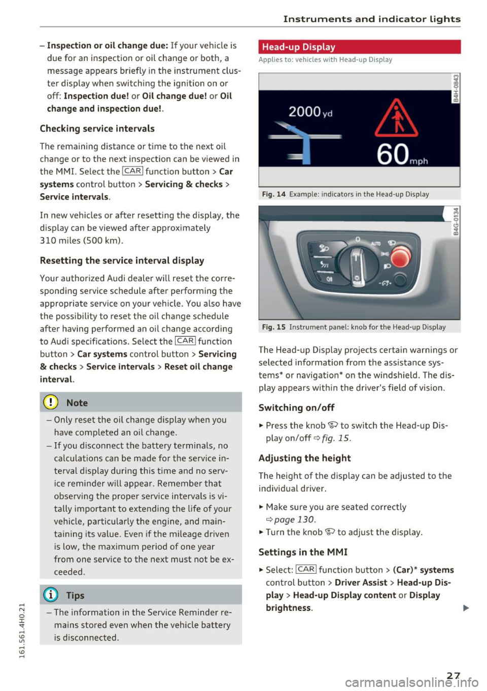
The Head-up Display projects certain warnings or
selected information from the assistance sys
tems* or navigation* on the windshield . The dis
play appears wit hi n the driver's field of vision.
Switching on/off
.,. Press the knob~ to switch the Head-up Dis-
play on/off
c:> fig. 15 .
Adjusting the height
The height of the display can be adjusted to the
individual driver.
.,. Make sure you are sea ted correctly
i::>page 130 .
.,. Turn the knob~ to adjust the display .
Settings in the MMI
.,. Select: !CAR ! function button > (Car)* systems
control button > Driver Assist > Head-up Dis
play
> Head-up Display content or Display
brightness.
27
Page 30 of 302
Instrumen ts and ind icator ligh ts
Displ ay content
In the MMI, yo u can specify which informat ion
should be d isplayed such as navigat ion info rma
tion* or Night vision assistant*.
The speed display and some of the red indicator
lights cannot be hidden in the MMI.
D is pl ay bri ghtness
You can adjust the disp lay brightness in the MMI.
The display brightness decreases automatically
as the amount of light decreases. The bas ic level
of br igh tness is adjusted w ith the inst rument
il
lum ina tion ¢ page 51.
(D Note
To prevent scratches on the g lass cove ring the
Head-up D isplay, do not place any objects in
the projection opening.
(j) Tips
- Sunglasses w ith polar izat ion fi lters and un
favorab le lighting conditions can affect the
display.
- An optimum display depends on the seat
position and the height of the Head- up D is
play .
- A specia l windshield is needed for the Head
up Disp lay fu nction .
- Fo r informat ion on cleaning, refer to ¢
ta
ble on page
208.
Open door /hood /rear lid warning
Fig. 16 Displ ay: d oor s an d r ear lid open
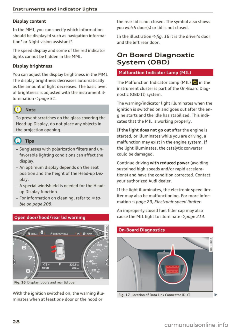
With the ignition switched on , the warning illu
m inates when a t least
one door or the hood or
28
the rear lid is not closed. The symbo l also shows
you
which door(s) or lid is not closed.
In the illustration
¢ fig . 16 it is the d river 's doo r
and the left rear door.
On Board Diagnostic
System (OBD)
Malfunction Indicator Lamp (MIL )
The Ma lfunction I ndi cator Lamp (M IU ¢.ij in the
i nstrument cluster is part of the On-Board Diag
nostic (OBD II) system .
The wa rni ng/indicator light ill uminates when the
i gnition is sw itched on and goes out after the en
gine starts a nd the idle has stab ilized . This indi
cates that the M IL is working proper ly .
If th e light do es not go out after the eng ine is
started, or illum inates while you are driving, a
malfunct ion may ex ist in the engine system. If
the light illuminates, the catalytic converte r
could b e damag ed .
Cont in ue drivi ng
with redu ced power (avoidi ng
sustai ned high speeds and/o r rapid accelera
tions) and have the condit ion corrected . Contact
your a uthorized Audi dea ler.
If the l igh t illum inates, the electronic speed lim
i ter may also be ma lfunctioning. For more infor
ma tion ¢
page 29, Electronic speed Limiter .
An improperly closed fue l filler cap may also
cause the MIL light to illuminate ¢
page 214.
On-Board Diagnostics
Fig. 17 Locat io n of Data L ink Co nnecto r (DL C)
Page 31 of 302

On-Board Diagnostics monitors the components
of your emission control system. Each monitored
component in your eng ine system has been as
signed a code . In case of a malfunction, the com
ponent will be identified and the fault stored as a
code in the control module memory .
The MIL light may also illuminate if there is a leak in the on-board fuel vapor recovery system.
If the light illuminates after a refueling, stop the
vehicle and make sure the fuel filler cap is prop
erly closed
¢ page 214.
In order to make an accurate diagnosis, the stor
ed data can only be displayed using special diag
nostic equipment (generic scan tool for OBD) .
In order to connect the special diagnostic equip
ment, push the plug into the Data Link Connector
(DLC) . The DLC is located to the right of the hood
release
c> fig . 17.
Your author ized Audi dealer or a qualified service
station can interpret the code and perform the necessary repair.
A WARNING
Do not use the diagnostic connector for per
sonal use. Incorrect usage can cause malfunc
tions, which can increase the risk of a colli
sion!
Electronic speed limiter
Your veh icle may be factory equipped with t ires
that are rated for a maximum speed of 130 mph
(2 10 km/h). This is less than the maximum speed
of your vehicle. To reduce the risk of sudden tire
failure and loss of control if the vehicle is operat
ed at excessive speeds, your vehicle also has an
electronic speed limiter. The electronic speed limiter prevents your vehicle from going faster
than the tir e speed rating . For more information
¢page 243 .
If the engine control unit receives faulty vehicle
road speed signals, the Malfunction Indicator
L amp
(Mil) Ill will illuminate . If this occurs,
contact the nearest authorized Audi dealer for
assistance .
Instruments and indicator lights
S8
Your vehicle 's top speed is elect ronically lim ited
to 155 mph (250 km/h).
If the engine control unit receives faulty vehicle
roadspeed signals, the Malfunction Indicator
Lamp (MIL)¢• will illuminate. If this occurs,
contact the nearest authorized Audi dealer for
assistance.
A WARNING
-A lways observe the posted speed limits and
adjust your speed to suit prevailing road, traf
fic and weather conditions. Never drive your
vehicle faster than the maximum speed rating
of the tires installed.
29
Page 33 of 302

Removing the mechanical key
Fig. 19 R emote control master key: removing the mechani·
ca l key
• Press the release button @¢fig. 19.
• Pull the mechanical key @ out of the master
key.
Using the mechan ica l key, you can:
- lock and unlock* the storage compartment on
the passenger's side¢
page 73.
- lock and unlock the vehicle manually
¢page 35.
-lock the front and rear passenger doors me
chanically¢
page 36.
-unlock the luggage compartment lid manually
¢page 39.
Check light and battery in the master key
Fig. 20 Remote master key: Remov ing the battery holder
Check light in the ma ste r key
The check light®¢ fig. 20 in the master key
provides information about different conditions.
• The check light turns on briefly once when a
button is pressed, and during an "inquiry" by
the conven ience key system.
Open ing and closing
• If the check light does not come on, the battery
is dead and has to be replaced. In addition,
when the battery is dead the
!I ind icator light
appears in the instrument cluster display as
well as the message
Please change the key
battery .
Ma ster key battery replacement
• Remove the mechanical key ¢page 31.
• Press the re lease button @¢ fig. 20 on the
battery holder and at the same time pull the
battery holder out of the master key in the di
rection of the arrow .
.. Install the new batte ry CR 2032 with the"+"
sign facing down.
.. Push the battery holder carefully into the mas
ter key .
.. Insta ll the mechanical key .
@ For the sake of the environment
Dispose of dead batteries properly so as not
to pol lute the environment.
(D Tips
The replacement battery must be the same
specification as the original.
Electronic immobilizer
The immobilizer helps to prevent unauthorized
use of your vehicle.
A computer ch ip inside your key automatically
deact ivates the electronic immob ilizer when the
key is inside the vehicle. When you remove the
key from the vehicle, the elect ronic immob ilizer
is automatically activated once again .
& WARNING
-
Always take the key with you when you leave
the vehicle. The key can disarm the electronic
engine immobilizer and permit an unauthor
i zed person to start the engine and enable op
eration of the vehicle systems such as power
window or power sunroof leading to serious
personal injury.
31
Page 47 of 302
Programming the buttons
Applies to: vehicles with garage door opener (Homelink)
Fig . 4 1 Head lin er: co ntro l uni t
You can program both f ixed code and rol ling code
systems using this procedure.
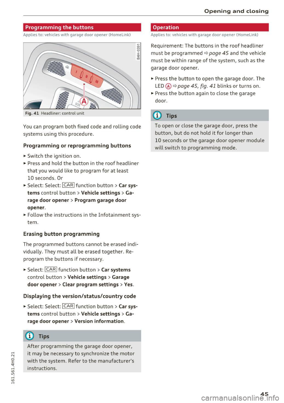
Programming or reprogramming buttons
• Switch the ignition on.
• Press and hold the button in the roof headliner
that you would like to program for at least
10 seconds. Or
• Se lect: Se lect: ~IC~ A~R~ lfunction button>
Car sys
tems
control b utton > Vehicle settings > G a
rage door opener
> Program garage door
opener .
• Fo llow the ins truc tions i n the I nfot ainme nt sy s-
tem .
Erasing button programming
The programmed buttons cannot be e rased indi
vid ually. They must all be e rased toget her. Re
p rogram the buttons if necessa ry.
• Se lect: ICARI funct ion but ton>
Car sy stems
contro l bu tton > Vehicle setting s > Garage
door opener > Clear program settings > Yes .
Displaying the version /status/country code
• Se lec t: Se lect: ICARlfunction button> Car sys
tems
control button > Vehicle settings > Ga
rage door opener > Vers ion information .
(D Tips
After programm ing the ga rage door opener,
it may be necessary to synchro nize t he motor
w it h the system . Re fer to the ma nufac tu rer's
in str uctions.
Open ing and closing
Operation
Applies to: vehicles with garage door opener (Home link)
R equireme nt: The but tons in the roof headli ne r
mus t be p rogramme d
~ page 45 and the veh icle
mus t be wit hin range of the system, such as the
garage doo r opener.
• Press the bu tton to ope n the garage door. The
L E D @ ~
page 45, fig . 41 blink s or tur ns on .
• Press the bu tton ag ai n to close the g arage
door.
@ Tips
To ope n or close the g arage do or, pres s th e
b utton, but do no t hold it for longer than
1 0 seco nds or t he garage door opener module
will switch to p rogramming mode.
45
Page 49 of 302
detected by the light sensors. So always
switch on the headlights
io u nder these
weather cond itions and when driving in the
dark.
- Crashes can happen when you cannot see
the road ahead and when you cannot be
seen by other motorists. Always turn on the
headlights so that you can see ahead and so
that others can see your car from the back.
- The rear fog lights should only be turned on in accordance with traffic regulat ion, as the
lights are br ight for following traffic.
- Please obse rve legal regulations when using
the light ing systems described .
@ Tips
-The light sensor* for automatic dynam ic
headlight range control* is located in the
rear view mirror mount . You should there
fo re not app ly any st icke rs to the windshie ld
i n this area in order to prevent malfunctions
or fail ures.
- In the event of a light sensor malfunction,
the driver is not ified in the i nstr ument clus
ter display
~page 22.
-You w ill hear a warning tone if yo u open the
driver door when the exter io r lights are
switched on .
- In coo l o r damp wea ther, the inside of the
headlig hts, turn s ignals and tai l ligh ts can
fog over d ue to the temperature d if f erence
between the inside and outside. They will
clear short ly after switch ing them o n. This
does not affect the serv ice life of the light
i ng .
Lights and V ision
Emergency flasher
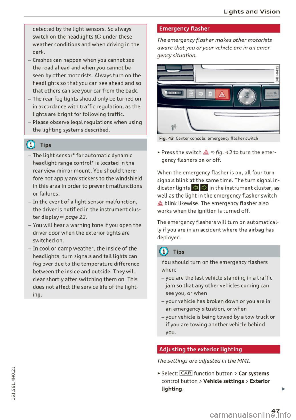
The emergency flasher makes other motorists
aware that you or your vehicle ore in on emer
gency situation .
~ ~
~ ·--==-..-,-.,..= ..... ·=- -,
I
Fig . 43 Cen te r console: emergency flas her swi tch
• Press the switch~ ~fig . 43 to turn the eme r-
gency flashers on or off .
When the emergency flasher is on, a ll fo ur turn
signals blin k at the same time. The turn signal in
dicator lights
II B in the instrument cluster, as
well as the light in the emergency flasher switch
~ b link likew ise. The emergency flasher also
works when the ign ition is turned off .
The emergency flashers will turn on automatical ly if you are in an accident where the airbag has
deployed .
(l') Tips
You should turn on the eme rgency flashers
when:
- you a re t he last vehicle standing in a traffic
jam so that any other vehicles coming can see you, or when
- your vehicle has broken down or you are in
an emergency situat ion, or when
- your vehicle is be ing towed by a tow truck or
if you a re towing another vehicle behind
yo u.
Adjusting the exterior lighting
The settings ore adjusted in the MMI.
• Select: I CAR I function button > Car s yste ms
control button > Vehicle settings > Exte rior
lighting .
47
Page 51 of 302

.... N
cluster illuminates when the high beams are
on.
- The
headlight flash er works only as long as you
hold the lever -even if there are no lights
turned on. The indicator light
& in the instru
ment cluster illum inates when you use the
headlight flasher.
A WARNING
Do not use the high beam or headlight flasher
if you know that these could bl ind oncoming
traffic.
High beam assist
App lies to: vehicles with high beam assist
The high beam assist automatically switches the
high beams on or off, depending on the sur
roundings and traffic conditions.
Fig. 45 Turn s ignal and h igh bea m lever : Turning on and
off the high beam assist
Activating high beam assist g
,.._ 0 ± .,. a,
Requirement:
The light switch must be in the AU
TO pos ition, the low beam headlights must be on
and the high beam assist must be switched on in
the Infota inment ~
page 47 .
.. Press the lever forwards (Din order to activate
the high beam assist. The indicator light
II
turns on in the instrument cluster display and
the high beams switch on or off automatically.
T he ind icator light
B turns on if the high
beams were switched on.
Switching the high beams on/off manually
a Requirement: High beam ass ist is activated . J:
'SI: ....
If the high beams did not switch on/off automat
ica lly when expected, you may instead switch
them on/off manually:
.. To switch the high beams on manually, press
the lever forwards (D. The indicator light
II
turns on.
.. To switch the high beams off manually, pull the
lever backwards @. The high beam assist is de
activated.
Operating the headlight flasher
.. To operate the flashers while the high beam as
sist is active and the high beams are switched
off, pull the lever into position@. The high
beam ass ist will remain active.
Messages in the instrument cluster display
Headlight assist: System fault
Drive to your authorized Audi dealer immediate ly
to have the malfunction corrected. You can still
switch the high beams on or off manually .
Headlight assist: Unavailable . No camera view
The camera view is blocked, for example by a
sticker or debris.
The sensor is located between the interior rear
view m irror and the windshield. Therefore, do not
place any stickers in this area on the windshield .
Service setting
There is a different sensitivity setting for servic
ing. This setting can be activated by pressing and
ho lding the button on the interior rearview mir
ror for more than 18 seconds. The LED next to
the button blinks three times. If you have acci dentally selected th is service function, the origi
nal sens itiv ity will be automat ically restored the
next t ime you sw itch the ignition on.
A WARNING
High beam assist is only intended to assist
the driver. The driver is still responsible for
controlling the headlights and switching the
high beams on and off manua lly depending
on traffic, lighting and visibility conditions.
Fail ure to intervene manually may lead to r isk
Ill>-
49
Page 53 of 302
Adjusting the brightness
You can adj ust the brigh tness for the four zones
Front top , Front f ootwell , Rea r top and Rear
footwell
or for All area s at the same time.
Selecting a color profile
You can se lect from the Ivory , Polar and Rub y/
Polar
color profi les.
@ Tips
The settings are automatically stored and as
sig ned to the remo te control key that is in
use .
Instrument illumination
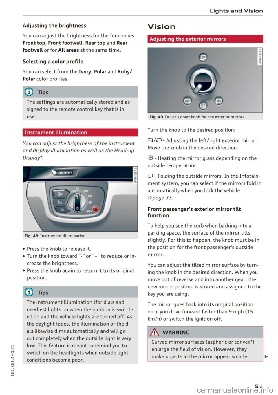
You can adjust the brightness of the instrument
and display illumination as well as the Head-up
Display* .
Fig . 4 8 Instr ument ill um ination
.. Press the knob to release it.
.. Turn the knob toward"-" or"+" to reduce or in
crease the brightness .
.. Press the knob aga in to return it to its orig inal
pos itio n.
(D Tips
The instrument ill umination (for dia ls and
needles) lights o n when the igni tion is switch
ed on and t he ve hicle lights are tu rned off. As
t he daylight fade s, the illum ina tion of the di
a ls likewi se dims au tom atic ally a nd w ill go
ou t comp lete ly when the outsi de light is very
low. This feature is meant to rem ind you to
sw itch on the head lights when o utside light
conditions become poor.
Lights and V ision
Vision
Adjusting the exterior mirrors
Fig. 4 9 Driver 's doo r: knob fo r the exte rio r mirr ors
Turn the knob to the des ired position:
Q/P -Adjusting the left/right e xterior mirror.
Move the knob in t he des ired direct ion .
Qill -Hea ting the mir ror glass depend ing o n the
outside tempe rature .
8 -Foldi ng the o utside mir ro rs . In the Infotai n
ment system , you can se le ct if t he m irro rs fo ld in
a utomat ically when you lock the vehi cle
~ page 33.
Front passenger 's exterior mirror tilt
function
T o help you see the curb when backing into a
parking space, the su rface o f the mirro r tilts
s li ght ly . For this to happen, the knob must be in
the position for the front passenger's outside
mirror .
Yo u can adjus t the tilted mir ro r sur face by turn
i ng the knob in the desired d irect ion . When you
move out of reverse and into another gea r, the
new m irror position is stored and assigned to the
key you are using.
T he m irror goes back into its or iginal pos ition
once you drive forward faster t han 9 mph (15
km/h) or sw itch the ignition off.
A WARNING
-Cu rved m irror surfaces (aspher ic or convex *)
enlarge the field of v is ion . However, they
make objects in the mirro r appea r small er
51
Page 58 of 302
Lights and Vision
.. Turn the service position off.
_& WARNING
For your safety, you should replace the wiper
blades once or twice a year. See your author
ized Audi dealer for replacement blades.
- The windshield wiper blades must only be
folded away when in the serv ice position!
Otherwise, you risk damaging the paint on
the hood or the windshield wiper motor.
- You should not move your vehicle or press
the windshield wiper lever when the wiper
arms are folded away from the windshield.
The windshield wipers would move back in
to their original position and could damage
the hood and windshield.
- To help prevent damage to the wiper sys
tem, a lways loosen blades which are frozen
to the windshield before operating wipers.
- To help prevent damage to wiper blades, do
not use gasoline, kerosene, paint thinner, or
other solvents on or near the w iper blades.
- To help prevent damage to the wiper arms
or other components, do not attempt to move the wipers by hand.
(D Tips
- Commercial hot waxes applied by automat ic
car washes affect the cleanability of the
windsh ield.
- You can also use the serv ice position, for ex
ample, if you want to protect the windsh ield
from icing by us ing a cover.
- You cannot activate the service position
when the hood is open.
56
Digital compass
Switching the compass on and off
Applies to: vehicles with digital compass
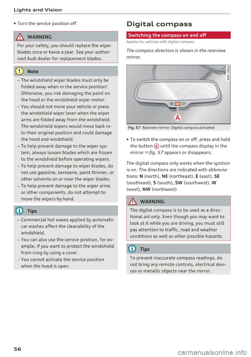
The compass direction is shown in the rearview
mirror.
[ j
Fig . 57 Rearv iew m irror: Digital compass activated
the button @until the compass display in the
mirror
c:!:> fig. 57 appears or disappears.
The dig ital compass only works when the ignit ion
is on. The directions are indicated with abbrevia
tions:
N (north), NE (northeast), E (east), SE
(southeast), S (south), SW (southwest), W
(west), NW (northwest).
_& WARNING
The digital compass is to be used as a direc
tional aid only. Even though you may want to
look at it while you are driving, you must still
pay attention to traff ic, road and weather
conditions as well as other possible hazards.
(0 Tips
To prevent inaccurate compass readings, do
not bring any remote controls, electrical devi
ces or metallic objects near the mirror.
-