AUDI A8 2017 Owners Manual
Manufacturer: AUDI, Model Year: 2017, Model line: A8, Model: AUDI A8 2017Pages: 354, PDF Size: 88.68 MB
Page 321 of 354

C) C0 ....
"' " "' .... 0 0 :r
Tires with unidirectional tread design must be
mounted with their tread pattern pointed in the
right dir ection .
Using a spare tire w ith a tread pattern
intended for use in a specific direction
When using a spare t ire with a tread patte rn in
ten ded fo r use in a specific direction, please note
the following:
- The direct io n of rotat io n is ma rked by an a rrow
o n the side of the tire .
- If the spare tire has to be installed in the incor
rect d irection, use the spare tire only tempora
rily s ince the tire w ill not be ab le to achieve its
opt imum performanc e ch a rac teristics wi th re
g ard to a quaplaning, noi se and we ar.
- We recommend that you pay particular atten
t io n t o thi s fa ct du ring we t wea ther and that
y ou adju st your s peed to m atch r oad co ndi
ti ons .
- R eplace t he flat tir e wi th a new one and have i t
i n st alled on yo ur vehicle as soon as possible to
r es to re the handlin g advanta ges of a unidi rec
tiona l tire .
Notes on wheel changing
P lease read the info rmation
<=> page 29 0 if you
are going to use a spare tire which is different
from t he tires on your vehicle.
Afte r you change a ti re:
- Check the tire pressure on the spare immedi
ately after installation.
- Have the wheel bolt tightening torque
checked with a torque wrench as soon as pos
sible by your authorized Audi dealer or a
qualified service station.
- With steel and alloy wheel rims, the wheel
bolts are correctly tightened at a torque of 90
ft lb (120 Nm).
- If you notice that the wheel bolts are corroded
and diff icult to turn while changing a tire,
they should be replaced before you check the
tightening torque .
Emergency assistance
-Replace the flat tire with a new one and have
it installed on your vehicle as soon as possi
ble. Remount the wheel cover .
Until then , drive with extra care and at reduced
speeds.
A WARNING
- If you are goin g to equip yo ur ve hicle with
tires or r ims which diffe r from those which
were factory installed, the n be sure to read
the information
r:> page 290.
- A lways make sure the dama ged w heel or
e ven a flat tire and the jack and tool kit ar e
prope rly sec ured in the luggage compa rt
men t and a re not loose in the passenger
compa rtme nt.
- In an accident or sudde n maneuv er th ey
co uld f ly forward , inju ri ng a nyone in the ve
h icle.
- Always store damaged w he el, jack and tools
se cur ely in the luggage compartment. Ot h
e rw ise, i n an accide nt or sud den mane uve r
t hey could fly forw ard, causing inju ry to pas
s e ng ers i n th e ve hicle.
Spare tires
General information
App lies to : vehicles wi th spare tire/space-saving spare tire
(co mp act s pa re t ire)
Fig . 28 3 Lu ggage co mpart m ent: ca rgo floo r cover fo lded
up wa rd
The spare tire is intended for s hort-term use on-
-
ly . Have the damaged tire checked and, if neces
sary, rep laced by an authorized A udi dealer or au
tho rize d Au di Serv ice Facility as soon as p ossible.
II>-
319
Page 322 of 354

Emerg ency assis ta nce
There are some restrictions on the use of the
spare tire. The spare tire has been designed spe
cifically for your type of vehicle. Do not replace it
with the spare tire from another type of vehicle.
There are different types of spare tires availab le
depending on the equipment
c::> page 320.
Remo ving t he spare tire
• Lift the cargo floor by the plast ic handle
~fig. 283.
• Hook the hand le into the luggage compartment
seal.
• Turn the handwhee l counter-clockwise and re-
move it.
• Remove the spare tire.
Sn ow c hain s
For technica l reasons, the use of snow chains on
the compact spare tire is not permitted.
If you have to drive with snow chains and a front
tire fa ils, mount the spare wheel in place of a
rear tire. Insta ll the snow cha ins on the rear tire
that you removed, and install that in p lace of the
front tire that failed.
A WARNING
-After installing a spare t ire, the tire pres
sure must be checked as quickly as poss ible.
- Do not drive faster than 50 mph (80 km/h)
with a compact spare tire. Driving faster
than that increases the risk of an accident.
- To reduce the risk of an accident, avo id fu ll
throttle acceleration, heavy braking, and
fast cornering with the compact spare t ire.
- To reduce the risk of an accident, never drive with more than one compact spare tire.
- Norma l summer or winter tires must not be
mounted on the compact spare wheel rim.
A WARNING
- Never use the spare tire if it is damaged or if
it is worn down to the tread wear indicators.
- If the spare tire is more than 6 years o ld,
use it only in an emergency and with ex
treme caution and careful dr iving.
- The spare tire is intended on ly for tempora
ry and short-term use. It should be replaced
320
as soon as possible with the normal whee l
and tire.
- For technical reasons, the use of tire chains
on the spare tire is not permitted. If it is
necessary to drive w ith tire chains, the spare
wheel must be mounted on the front axle in
the event of a flat in a rear t ire. The newly
ava ilable front wheel must then be installed
in place of the rear wheel w ith the flat tire.
Installing the tire chain befo re mounting
the wheel and tire is recommended.
- Loose items in the passenger compa rtment
can cause se rious personal injury during
ha rd braking or in an accident. Never store
the inflatable spare tire or jack and tools in
the passenger compartment .
Spare tire types
Fig. 284 Luggage compartment: space-sav ing spare tire
(compact spare tire)
(D Spare tire*
If you have to mount a spare tire oppos ite the
runn ing direction because of a flat tire, drive
ca refully and restore the cor rec t r unn ing d irec
tion as soon as poss ib le
¢page 319.
Page 323 of 354
0 co .... N ,..._
N .... 0 0 :c '
tire )*
The ti re pressure must be 6 1 PSI ( 4.2 ba r) .
Emergency assistance
321
Page 324 of 354
Fuses and bulbs
Fuses and bulbs
Electrical fuses
Changing fuses
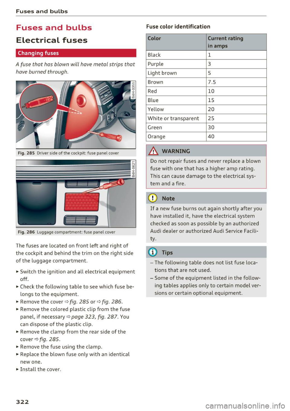
A fuse that has blown will have metal strips that have burned through .
Fig. 28 5 Driver s ide of th e cockp it: fuse panel cover
I l I
F ig. 2 86 Lu ggage compartment: fuse pane l cover
The fuses are loca ted on front left and r ight of
the cockpit and behind the trim on the right side
of the luggage compartment.
.. Swi tch the ignition and all e lec trica l equipment
off.
.. Check the following table to see which fuse be
lo ngs to the equipment .
.. Remove the cover
c::> fig. 285 or c:> fig . 286 .
.. Remove the colored plastic clip from the fuse
panel, if necessary
c:> page 323, fig. 287. You
can d ispose of the p lastic clip .
.. Remove the clamp from the rear s ide of the
cove r
c::> fig. 285 .
.. Remove the f use usi ng the clamp .
.. Replace the b low n fu se only wi th an identi cal
new one .
.. Install the cover.
322
Fuse color identification
Color Current rating
in amps
Black 1
Purple 3
Light brown 5
Brown 7.5
Red 10
Blue 15
Yellow 20
Wh ite or transpa re nt 25
Green 30
Orange 4 0
A WARNING
-
Do not repair fuses and never replace a blown
f u se with one that has a higher amp rat ing.
This ca n cause damage to t he e lectr ica l sys
tem and a fire.
(D Note
If a new fuse burns out again sho rtly after you
h ave insta lled it, have the electrical system
checked as soon as possible by an authorized
A udi dealer or authorized Aud i Service Fac ili
ty .
(D Tips
-The following table does not list fuse loca
tions that are not used .
- Some of the equipment listed in the fo llow
ing tables applies on ly to certai n model ver
sions or certa in optional equipment .
Page 325 of 354
C) C0 ....
"' " "' .... 0 0 :r
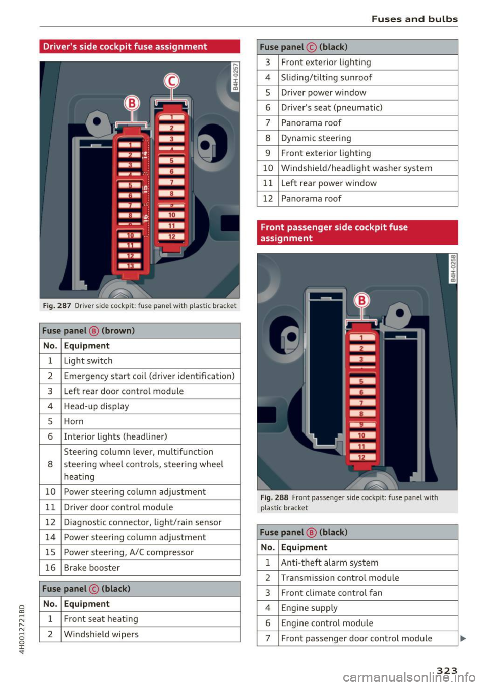
Fig. 287 Driver side cockpi t: fuse panel with plastic bracket
Fuse panel @ (brown)
No. Equipment
1 Light switch
2 Eme rgency start coil (driver identification)
3 Left rear door control module
4 Head-up display
5 Horn
6 Interior lights (headliner)
Steering column lever, multifunction
8 steering whee l controls, steering wheel
heating
10 Power steering column adjustment
11 Driver door control module
12 Diagnostic connector, light/rain sensor
14 Power steering column adjustment
lS Power steering, A/C compressor
16 Brake booster
Fuse panel © (black)
No. Equipment
1 Front seat heating
2 Windshield wipers
Fuses and bulbs
Fuse panel © (black)
3
Front exterior lighting
4 Sliding/tilting sunroof
s Driver power window
6 Driver's seat (pneumat ic)
7 Panorama roof
8 Dynamic steering
9 Front exterior lighting
10 Windshield/headlight washer system
11 Left rear power window
12 Panorama roof
Front passenger side cockpit fuse
assignment
Fig. 288 Fro nt passenger side cockpit: fuse panel with
plastic bracket
Fuse panel @ (black)
No. Equipment
1 Anti-theft alarm system
2 Transmission control module
3 Front climate control fan
4 Engine supply
6 Engine control module
7 Front passenger door control module
323
Page 326 of 354
Fuses and bulbs
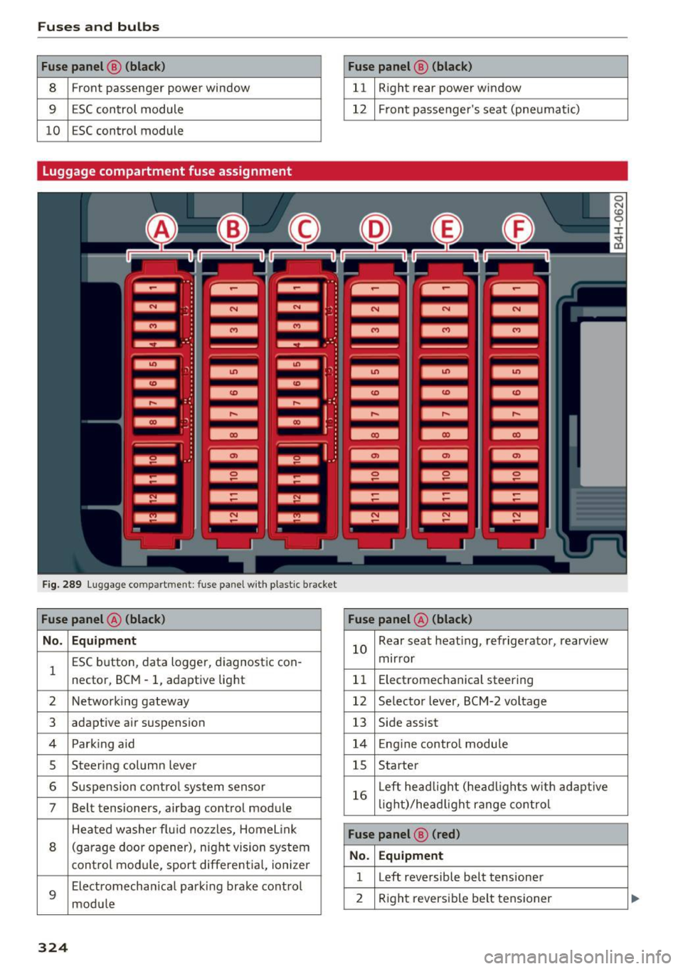
Fuse panel @ (black) Fuse panel@ (black)
8 Front passenger power window 11 Right rear power window
9 ESC control module 12 Front passenger's seat (pneumatic)
10 ESC control module
Luggage compartment fuse assignment
F ig. 289 Luggage compar tment: fuse panel with p lastic brack et
Fuse panel @ (black) Fuse panel@ (black)
No. Equipment
l
ESC button , data logger, diagnostic con-
nector, BCM -1, adaptive light 10
Rear
seat heating, refrigerator, rearview
mirror
11 Electromechanical
steering
2 Networking gateway 12 Selector lever, BCM-2 voltage
3 adaptive air suspension
13 Side assist
4 Park ing aid 14 Engin e control module
5 Steering column lever 15 Starter
6 Suspension control system sensor
7 Belt tensioners, airbag control module 16
Left
headlight (headligh ts with adaptive
lig ht)/head light range control
Heated washer flu id nozzles, Home Link
8 (garage door opener) , night vision system
control module, sport differential, ionizer
9
Electromechan ical parking brake control
module
Fuse panel ® (red)
No. Equipment
l Left reversible belt tensioner
2 Right reversible belt tensioner
324
Page 327 of 354
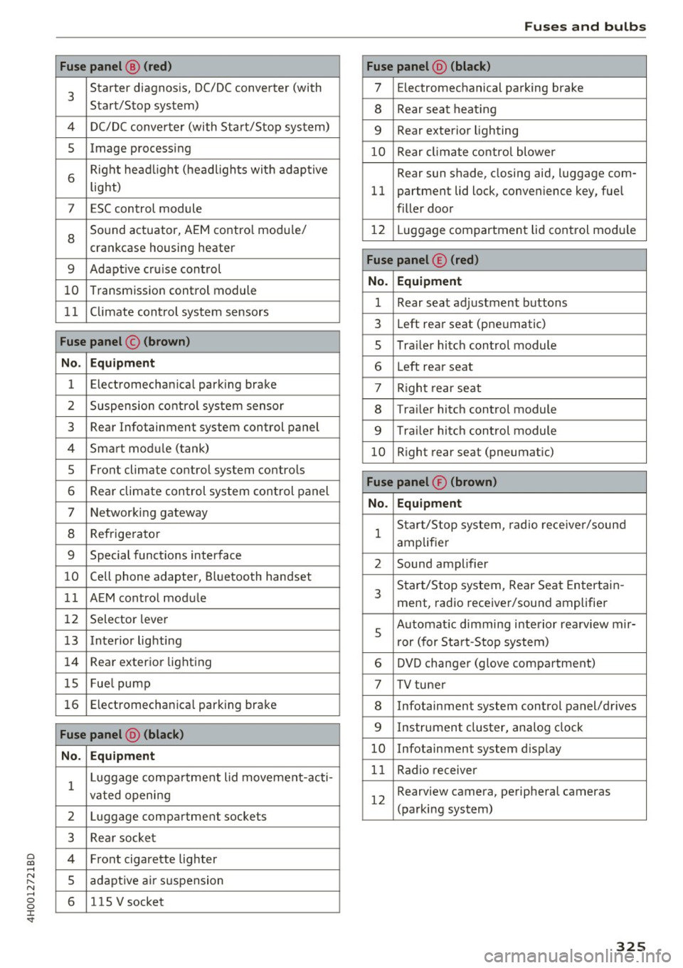
0 co .... N ,..... N .... 0 0 :c '
3
Starter diagnosis, DC/DC converter (with
Start/Stop system)
4 DC/DC converter (with Start/Stop system)
5 Image processing
6
Right headl ight (headlights with adaptive
light)
7 ESC control module
8
Sound actuator, AEM contro l modu le/
crankcase housing heater
9 Adapt ive cru ise control
10 Transmission control module
11 Climate control system sensors
Fuse panel © (brown)
No . Equipment
1 Electromechanical parking brake
2 Suspension control system sensor
3 Rear Infotainment system control panel
4 Smart mod ule (tank)
5 Front climate control system controls
6 Rear climate control system control panel
7 Networking gateway
8 Refrigerator
9 Special functions interface
10 Cell phone adapter, Bluetooth handset
11 AEM control module
12 Selector lever
13 Interior lighting
14 Rear exter ior light ing
15 Fue l pump
16 Electromechan ica l parking brake
Fuse panel @ (black)
No . Equipment
1 Luggage compa
rtment lid movement-acti-
vated opening
2 Luggage compartment sockets
3 Rea r socket
4 Front cigarette lighter
5 adaptive air suspension
6 1 lS V socket
Fuses and bulbs
Fuse panel @ (black)
7 Electromechanical parking brake
8 Rear seat heating
9 Rear exterior lighting
10 Rear climate control blower
Rear sun shade, closing aid, luggage com-
11 partment lid lock, convenience key, fuel
filler door
12 L uggage compartment lid control module
Fuse panel © (red)
No. Equipment
1 Rear seat adjustment buttons
3 Left rear seat (pneumatic)
s Trailer hitch control module
6 Left rear seat
7 R ight rear seat
8 Trailer hitch control module
9 Tra ile r hitch control module
10 Right rear seat (pneumatic)
Fuse panel® (brown)
No. Equipment
1
Start/Stop system, radio receiver/sound
amplifier
2 Sound amplifier
3
Start/Stop system, Rear Seat Entertain-
ment, radio receiver/sound amplifier
s
Automat ic dimming interior rearview mir-
r or (for Start-Stop system)
6 DVD changer (glove compartment)
7 TV tuner
8 Infotainment system control panel/drives
9 Instrument cluster, analog clock
10 Infotainment system display
11 Radio receiver
12
Rearview camera, peripheral cameras
(parking system)
325
Page 328 of 354
Fuses a nd bul bs
Bulbs
Replacing light bulbs
For your safety, we recommend that you have
your authorized Audi dealer replace burned out
bulbs for you.
It is becoming increasingly more and more diffi
cult to replace vehicle light bulbs since in many
cases, other parts of the car must first be re
moved before you are able to get to the bu lb .
This applies espec ially to the light bulbs in the
front of your car wh ich you can only reach
through the engine compartment .
Sheet metal and bulb holders can have sharp
edges that can cause ser ious cuts, and parts
m ust be correctly taken apa rt and then p roperly
put back together to help prevent breakage of
parts and long term damage from water that can
enter housings that have not been properly re
sealed.
For your safety, we recommend that you have
your authorized Audi dealer replace any bu lbs for
you, since your dealer has the proper tools, the correct bulbs and the expertise.
G as di sc harg e l am ps (Xe non li ghts):
Due to the high electrical voltage, have the bulbs
replaced by a qua lified technic ian . Headlights
with Xenon light can be identified by the high
voltage sticker.
LED headlights* require no maintenance. Please
contact your authorized Aud i dealer if a bulb
needs to be replaced.
A WARNING
Contact w ith high-voltage components of the
electrical system and improper rep lacement
of gas discharge (Xenon) headlight bulbs can
cause serious personal injury and death.
- Xenon bulbs are pressurized and can ex
plode when being changed.
- Changing Xenon lamps requires the special training, instructions and equipment.
- Only an a uthorized Audi dea ler or other
qualified workshop should change the bulbs
in gas discharge lamps .
326
A WARNING
-
There are parts with sharp edges on the open-
ings and on the bulb holders that can cause
serious cuts.
- If you are uncertain about what to do, have
the work performed by an authorized Audi
dealer or other qualified workshop. Ser ious
pe rsonal injury may resu lt from improperly
pe rformed wor k.
@ Tips
- If you must replace the light bulbs yourself,
always remember that the eng ine compart
ment of any vehicle is a hazardous area to
work in. Always read and heed all WARN INGS
'* page 271.
-It is best to ask your authorized Audi dealer
whenever you need to change a bulb.
Page 329 of 354

0 co .... N ,..... N .... 0 0 :c '
General
This chapter is intended for trained emergency
crews and working personnel who have the nec
essary tools and equipment to perform these
ope rations.
Starting by pushing or
towing
CD Note
Veh icles with an automatic transmission can
not be started by pushing or towing.
Starting with jumper
cables
If necessary, the engine can be started by con
necting it to the battery of another vehicle.
If the engine shou ld fail to start because of a dis
charged or weak battery, the battery can be con
nected to the battery of
another vehicle, using a
pair of jumpe r cables to start the engine.
Jumper cables
Use only jumper cables of suffic iently large cross
section
to carry the starter current safely. Refer
to the manufacturer's specifications.
Use only jumper cables with
insulated term inal
clamps which are dis tinct ly marked:
plus (+) cable in most cases colored re d
minus( -) cable
in most cases colored black.
A WARNING
Batteries contain electricity, acid, and gas.
Any of these can cause very serious or fatal in
jury. Follow the instructions below for safe
handling of your vehicle's battery.
- Always shield your eyes and avo id leaning
over the battery whenever poss ible.
- A dead battery can freeze at temperatures
around 32 °F (0 °C). If the vehicle battery is
frozen, you must thaw it before connecting
the jump start cab les. If you do not, this in-
Emergency situations
creases the risk of an explosion and chemi
cal burns. After jump starting the vehicle,
drive to an authorized Aud i dealer or author
ized Audi Service Facility immediately to
have the vehicle battery checked.
- Do not allow battery ac id to contact eyes or
skin . Flush any contacted area with water
immed iately.
- Improper use of a booster battery to start a
veh icle may cause an explosion .
- Veh icle batteries generate explosive gases.
Keep sparks, flame and lighted cigarettes
away from batter ies.
- Do not try to jump start any vehicle with a
low acid level in the battery .
- The voltage of the booster battery must also
have a 12-Volt rat ing. The capacity (Ah) of
the booster battery should not be lower
than that of the discharged battery. Use of
batter ies of different voltage or substantial
ly different "Ah" rating may cause an exp lo
sion and personal injury.
- Never charge a frozen battery. Gas trapped
in the ice may cause an explosion.
- Never charge or use a battery that has been
frozen . T he battery case may have be weak
ened.
- Use of batteries of different voltage or sub
stantially different capacity (Ah) rating may
cause an exp losion and injury . The capacity
(Ah) of the booster battery should not be
lower than that of the discharged battery.
- Before you check anything in the engine
compartment, always read and heed all
WARNINGS
qpage 271.
CD Note
-App lying a higher voltage booster battery
wi ll ca use expensive damage to sensitive
electronic components, such as control
units, relays, radio, etc.
- There must be no electrical contact between
the vehicles as otherwise current could al
ready start to flow as soon as the positive
(+) terminals are connected.
327
Page 330 of 354
Emergency situations
@ Tips
The discharged battery must be properly con
nected to the vehicle's electrical system .
When jump starting or charging the battery,
never connect the negative ground cable to
the battery negative post because the battery
manager system must be able to detect the
battery's state of charge. Always connect the
negat ive ground cable to the negative ground
pos t of the battery manager control unit.
Using the jump start
cable
Both jump start cables must be connected in the
correct order!
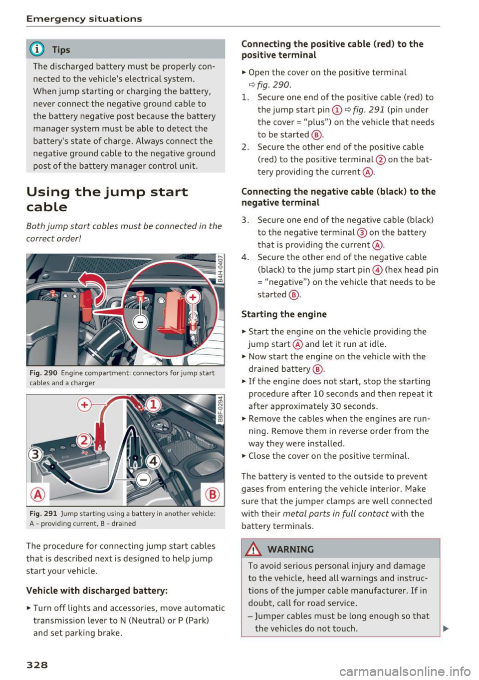
Fig. 290 E ngin e compartme nt: co nn ectors for jump start
cables and a charger
Fig. 291 Jump starting using a battery in anot her vehicle:
A -prov idin g current, B -drai ned
The procedure for connecting jump start cables
that is descr ibed next is designed to help jump
start your vehicle.
Vehicle with discharged battery:
... Turn off lights and accessories, move automatic
transmission lever to N (Neutral) or P (Park)
and set parking brake.
328
Connecting the positive cable (red) to the
positive terminal
... Open the cover on the positive terminal
qfig . 290.
1. Secure one end of the pos itive cable (red) to
t he jump start pin
(D q fig. 291 (pin under
the cover = "plus") on the vehicle that needs
to be started @.
2. Secure the other end of the positive cable
(red) to the positive terminal @on the bat
te ry provid ing the cur rent @.
Connecting the negative cable (black) to the
negative terminal
3. Secure one end of the negative cable (black)
to the negative terminal @ on the battery
that is providing the current @.
4. Secure the other end of the negative cable
(black) to the jump start pin@ (hex head pin
= "negative") on the vehicle that needs to be
started @.
Starting the engine
... Sta rt the eng ine on the vehicle providing the
jump start @and let it run at idle .
... Now start the engine on the vehicle with the
drained battery @.
... If the engine does not start, stop the starting
procedure after 10 seconds and then repeat it
after approximately 30 seconds .
... Remove the cables whe n the engi nes are run
ning. Remove them in reverse order from the
way they were installed.
" Close the cover on the positive terminal.
The battery is vented to the outside to prevent
gases from enter ing the vehicle interior. Make
sure that the jumper clamps are well connected
with their
metal parts in full contact with the
battery terminals .
A WARNING
To avoid serious personal injury and damage
to the vehicle, heed all warnings and instruc
tions of the jumper cable manufacturer. If in
doubt, call for road service .
- Jumper cables must be long enough so t hat
the vehicles do not touch.
Ill>