tire type AUDI A8 2020 Owners Manual
[x] Cancel search | Manufacturer: AUDI, Model Year: 2020, Model line: A8, Model: AUDI A8 2020Pages: 360, PDF Size: 95.38 MB
Page 152 of 360

High-voltage system
> Close the lever @) until it is resting on the con-
nector (2).
> Remove the connector (2) completely.
Attaching the cable
> Lift the lever @ up slightly.
> Insert the connector (2) into the control unit
just until you feel resistance.
> Lift the lever @ all the way up.
> Insert the connector (2) all the way into the
control unit.
> Close the lever ().
> Tighten the screw (3) using the screwdriver pro-
vided.
Z\ WARNING
— Note the warnings for charging > A\ in
Charging on page 140.
— Before switching a cable, always unplug the
power cable from the socket.
— Only change cables in a dry environment.
— The Audi charging system may only be used
as a complete unit consisting of the power
cables, the control unit, and the vehicle ca-
ble. Depending on the country, the total
length of the power cable, control panel and
vehicle cable may be restricted, for example
to 24.6 ft (7.5 m) in the USA. We recom-
mend using only cables approved by Audi.
G) Tips
The power cable with the power connector for
industrial sockets and the Audi charging sys-
tem control unit are designed to work togeth-
er. Changing the power cable to another con-
nector type may reduce the available charging
power of the entire system.
150
Wall mount clip
Applies to: vehicles with plug-in hybrid drive and wall mount
clip
[RAZ-0638|
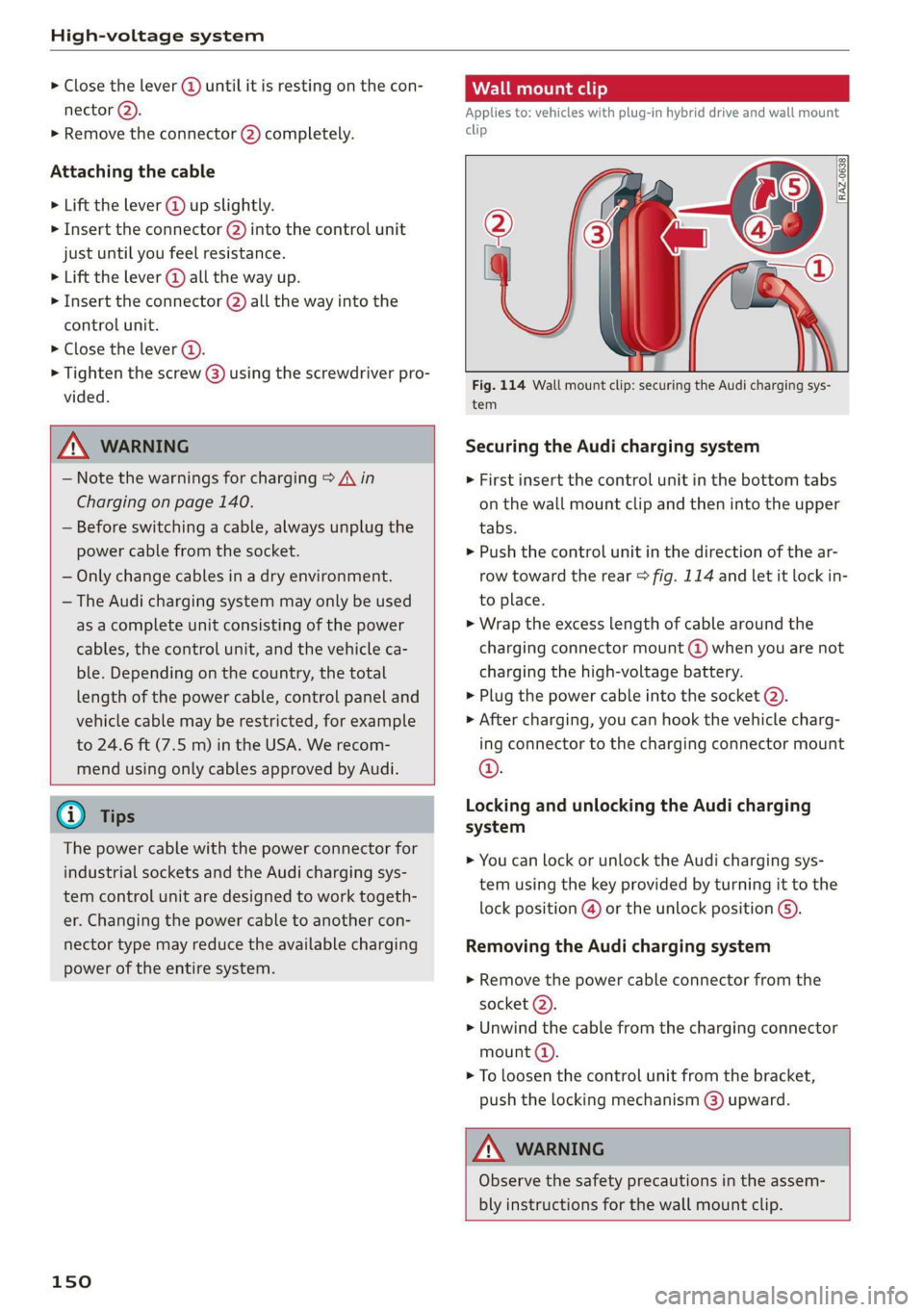
Fig. 114 Wall mount clip: securing the Audi charging sys-
tem
Securing the Audi charging system
> First insert the control unit in the bottom tabs
on the wall mount clip and then into the upper
tabs.
» Push the control unit in the direction of the ar-
row toward the rear > fig. 114 and let it lock in-
to place.
> Wrap the excess length of cable around the
charging connector mount @) when you are not
charging the high-voltage battery.
> Plug the power cable into the socket (2).
» After charging, you can hook the vehicle charg-
ing connector to the charging connector mount
©.
Locking and unlocking the Audi charging
system
> You can lock or unlock the Audi charging sys-
tem using the key provided by turning it to the
lock position @) or the unlock position @).
Removing the Audi charging system
> Remove the power cable connector from the
socket @).
> Unwind the cable from the charging connector
mount (a).
> To loosen the control unit from the bracket,
push the locking mechanism @) upward.
ZA\ WARNING
Observe the safety precautions in the assem-
bly instructions for the wall mount clip.
Page 242 of 360

Navigation
— Overview: the entire route from the vehicle po-
sition to the destination or the next stopover is
displayed on the map. The map is oriented to
the north.
Automatic zoom
— On: the map scale adapts automatically de-
pending on the type of road being traveled (ex-
pressway, highway, other roads) so that you al-
ways have an optimal overview of the road
ahead. When route guidance is active, the scale
is adjusted automatically for a better detailed
view when there are upcoming maneuvers.
— Intersection: when route guidance is active, the
scale is adjusted automatically for a better de-
tailed view when there are upcoming maneu-
vers.
— Off
MMI map contents/Map content: You can switch
the display of additional information (such as
POIs) on the map in the upper display on or off.
Note the following for the 3D city model > ©.
Voice guidance
Voice guidance: you can adjust the navigation
prompts. With the Traffic setting, the MMI will
only give prompts if there are traffic incidents on
your route.
Voice guidance during phone call
Entertainment fader during navigation: the au-
dio playback volume is temporarily lowered when
navigation prompts are active.
Route criteria
You can adjust which route criteria should be al-
lowed or avoided for the route calculation.
HOV/carpool lanes
Highways
Toll roads
Ferries
Route information
When this function is switched on and route
guidance is active, route information @
240
=> page 231, fig. 163 is displayed. The next ma-
neuver will be displayed at the bottom. POIs and
traffic information will also be displayed. Press
route
information to display a preview of the next
maneuver on the map. You can switch the follow-
ing information on or off in route information.
— POIs along the route
— Traffic information
Personal route assistance
Personal route assistance is switched off at the
factory.
Your trips are recorded and destinations are sug-
gested by the MMI when this function is switched
on > page 233.
Trailer mode
Trailer mode is switched off at the factory.
When the function is switched on, the maximum
permitted speed for vehicles with trailers is in-
cluded during route guidance and the calculated
arrival time is adjusted accordingly. When the
function is switched on, the symbol @)
=> page 231, fig. 163 is displayed on the map.
Presentation mode
In presentation mode, the system simulates driv-
ing along the planned route without the vehicle
actually moving. You can use Specify starting
point when you would like to calculate a route
starting
from a location other than the current
vehicle position, for example. Simulating route
guidance: start route guidance and press Presen-
tation mode.
() Note
Read the information about Audi connect, and
be sure to note the connectivity costs section
=@ in General information on page 216.
Gi) Tips
You can adjust the volume of navigation
prompts during voice guidance using the
On/Off knob > page 20. Also see > page 266.
Page 324 of 360

Emergency assistance
To benefit fully from the advantages of the uni-
directional tire design, you should replace faulty
tires as soon as possible and restore the correct
running direction on all of the tires.
> Reinstall the caps on the wheel bolts if necessa-
ry.
> Store the vehicle tool kit in its designated
place.
> If the removed wheel does not fit in the spare
wheel well, store it securely in the luggage
compartment > page 100.
> Check the tire pressure on the installed wheel
as soon as possible.
> Correct the tire pressure and store it in the MMI
=> page 308.
> The wheel bolt tightening specification must be
90 ft lbs (120 Nm). Have it checked as soon as
possible with a torque wrench. Drive carefully
until then.
> Have the faulty wheel replaced as quickly as
possible.
Space-saving spare tire
Applies to: vehicles with space-saving spare tire (compact
spare tire)
The spare tire is intended for short-term use only.
Have the damaged tire checked and replaced if
necessary by an authorized Audi dealer or author-
ized Audi Service Facility as soon as possible.
There are some restrictions on the use of the
compact spare tire. The compact spare tire has
been designed specifically for your type of vehi-
cle. Do not replace it with the spare tire from an-
other type of vehicle.
The compact spare tire is located in the luggage
compartment under the cargo floor cover
> page 316.
The tire pressure must be 61 PSI (420 kPA).
Snow chains
For technical reasons, the use of snow chains on
the compact spare tire is not permitted.
322
If you have to drive with snow chains and a front
tire fails, mount the spare tire in place of a rear
tire. Install the snow chains on the rear tire that
you removed, and install that in place of the
front tire that failed.
ZA\ WARNING
— After installing a spare tire, the tire pressure
must be checked as soon as possible.
— Do not drive faster than 50 mph (80 km/h)
with a compact spare tire. Driving faster
than that increases the risk of an accident.
— To reduce the risk of an accident, avoid hard
acceleration or braking and driving fast
around curves with the compact spare tire.
— To reduce the risk of an accident, never drive
with more than one compact spare tire.
— Normal summer or winter tires must not be
mounted on the compact spare wheel rim.
Jump starting
You should only perform the steps that follow if
you have the necessary tools and technical ex-
pertise.
If the engine does not start because the vehicle
battery is drained, you can jump start your vehi-
cle using another vehicle. Jump start cables are
needed to do this.
Both vehicle batteries must have 12 V nominal
voltage. The voltage capacity (Ah) of the vehicle
battery that is giving power must not be less
than the capacity of the drained vehicle battery.
Jump start cable
Only use a jump start cable with a large enough
diameter. Note the manufacturer's specifica-
tions.
Only use a jump start cable with insulated termi-
nal clamps.
Positive cable - usually red.
Negative cable - usually black.