AUDI ALLROAD 2000 Owners Manual
Manufacturer: AUDI, Model Year: 2000, Model line: ALLROAD, Model: AUDI ALLROAD 2000Pages: 306, PDF Size: 9.95 MB
Page 281 of 306
DO-IT-YOURSELF SERVICE----------------------
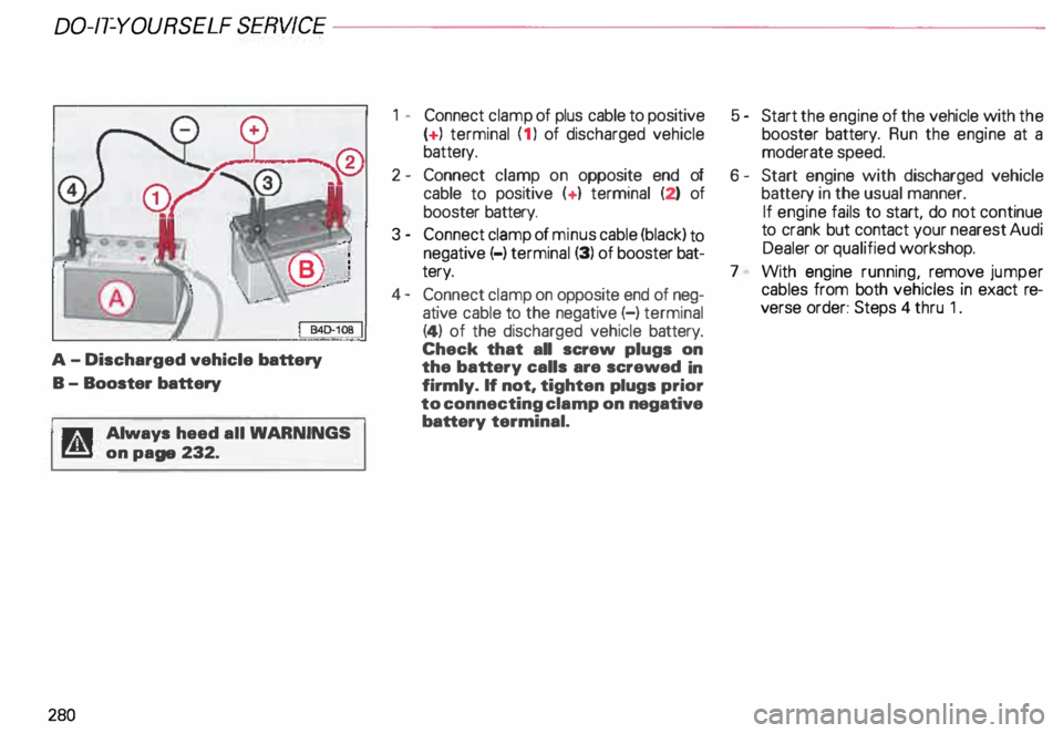
A-
Discharged vehicle battery
B - Booster battery
11r,:!1 Always heed all WAR NINGS
r!!l on page 232.
280 1
- Connect clamp of plus cable to positive
( + ) terminal (1 ) of discharged vehicle
battery.
2 - Connect clamp on opposite end of
cable to positive (+ ) terminal (2) of
booster battery.
3 - Connect clamp of minus cable (black) to
negative (-) terminal (3) of booster bat
tery.
4- Connect clamp on opposite end of neg
ative cable to the negative (-) terminal
(4) of the discharged vehicle battery.
Check that all screw plugs on
the battery calls are screwed in
firmly. If not, tighten plugs prior
to connecting clamp on negative
battery terminal. 5
- Start the engine of the vehicle with the
booster battery. Run the engine at a
moderate speed.
6- Start engine with discharged vehicle
battery in the usual manner.
If engine fails to start, do not continue
to crank but contact your nearest Audi
Dealer or qualified workshop.
7 With engine running, remove jumper
cables from both vehicles in exact re
verse order: Steps 4 thru 1.
Page 282 of 306
---------------------DO-IT-YOURSEL F SERVICE
Emergency towing with commercial tow truck
The following information is to be used by
commercial tow truck operators who know
how to operate their equipment safely.
General hints
• Never tow your Audi otherwise
this will cause damage to the engine
and transmission.
• Never wrap the safety chains or
winch cables around the brake lines.
• To prevent unnecessary damage.
your Audi must be transported with
a car carrier (flat bed truck).
To load the vehicle on to the flat bed.
use the towing loop found in the ve
hicle tool kit and attach to the front
anchorage.
�W ARNING
A towed vehicle is not safe for pas
sengers. Never allow anyone to
ride in a towed vehicle for any rea
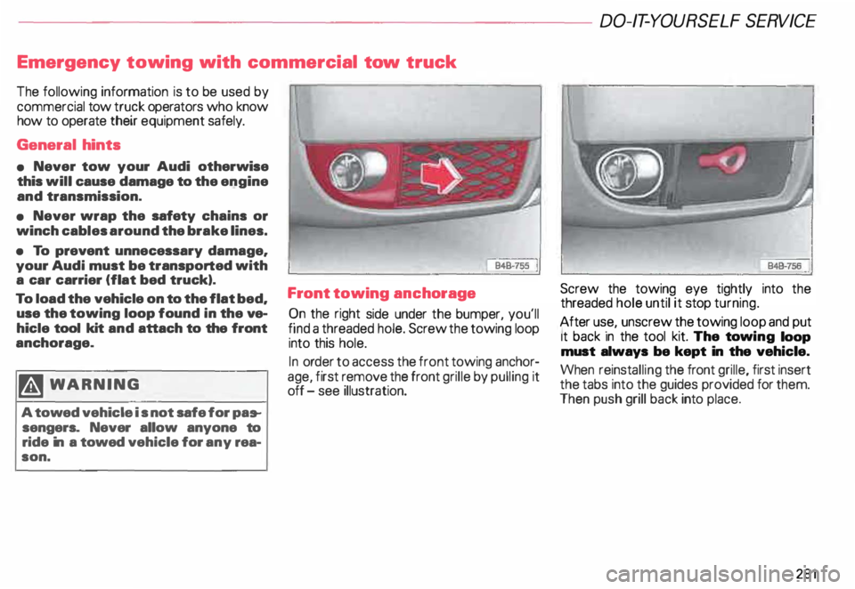
son. Front towing
anchorage
C? n the right side under the bumper, you'll
fmd a threaded hole. Screw the towing loop
into this hole.
In ord .er to access the front towing anchor
age, f1rst remove the front grille by pulling it
off -see illustration. Screw the towing eye tightly
into the
threaded hole until it stop turning.
After us .e, unscrew the towing loop and put
1t back In the tool kit. The towing loop
must always be kept in the vehicle.
When reinstalling the front grille, first insert
the tabs into the guides provided for them.
Then push grill back into place.
281
Page 283 of 306
00-/T-YOURSELF SERV/CE----------------------
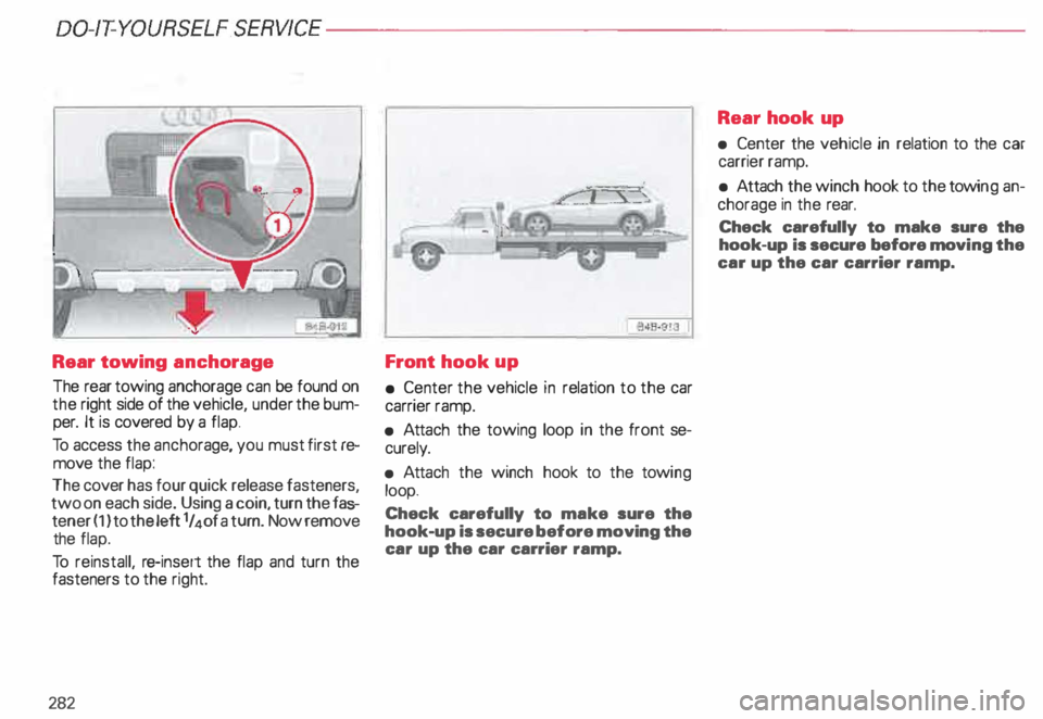
Rear towing anchorage
The rear towing anchorage can be found on
the right side of the vehicle, under the bum
per. It is covered by a flap.
To access the ancho rage, you must first re
move the flap:
The cover has four quick release fasteners,
two on each side. Using a coin, turn the fas
tener ( 1) to the left 1 I 4 of a turn. Now remove
the flap.
To reinstall, re-insert the flap and turn the
fasteners to the right.
282 Front
hook up
• Center the vehicle in relation to the car
carrier ramp.
• Atta ch the towing loop in the front se
curely.
• Atta ch the winch hook to the towi ng
loop.
Check carefully to make sure the
hook-up is secure before moving the
car up the car carrier ramp. Rear
hook up
• Center the vehicle in relation to the car
carrier ramp.
• Attach the winch hook to the towi ng an
chorage in the rear.
Check carefully to make sure the
hook-up is secure before moving the
car up the car carrier ramp.
Page 284 of 306
Lifting
vehicle
Lifting with workshop hoist
and with floor jack
Notes
• The vehicle should never be lifted
or jacked up from underneath the
engine oil pan, the transmission
housing, the front or rear axle or the
body side members. This could lead
to serious damage.
The same lifting points as illus trated on the
next page for the hoist also apply when a
floor jack is used.
e To avoid damage to the under
body or chassis frame, it is neces
sary to insert a rubber pad between
the floor jack and the lift points.
• To prevent damaging the shock
absorbers when lifting the vehicle
with a jack or on a hoist, the level
selection must be in the jack mode.
See next page. �W
ARNING
• To reduce the risk of serious in
jury and vehicle damage, lift the
vehicle only at the special work
shop hoist and floor jack lift points
illus trated. Failure to lift the ve
hicle at these points could cause
the vehicle to tilt or fall from a lift
if there is a change in vehicle
weight distribution and balance.
This might happen, for example,
when heavy components such as
the engine block or transmission
are removed.
• When removing such heavy
components, anchor vehicle to
hoist or add correspo nding
weights to maintain the center of
gravity. Otherwise, the vehicle
might tilt or slip oH the hoist,
causing serious damage or person
al injur y. DO-IT-YOU
RSELF SERVICE
�� WARNING continued
• If you must lift your vehicle with
a floor jack to work underneath,
be sure the vehicle is safely sup
ported on stands intended for this
purpose.
• Before driving over a workshop
hoist, check that the vehicle weight
does not exceed the permissible lift
ing capacity of the hoist.
• Before driving over a workshop
hoist, ensure that there is suHicient
clearance between the hoist and
low parts of the vehicle.
283
Page 285 of 306
DO-IT-YOURSELF
SERVICE----------------------
Jack
mode
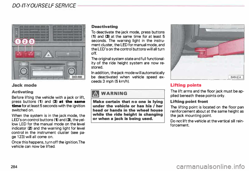
Activat ing
Before lifting the vehicle with a jack or lift,
press buttons (1) and (3) at the same
time for at least 5 seconds with the ignition
switc hed on.
When the system is in the jack mode, the
LED's on control buttons (1) and (3), the yel
low LED for the manual mode on the level
ind icator (2) and the warning light for level
control in the instrument cluster (see pa
ge 123) will all come on.
Once this happens, turn off the ignition. The
vehicle can now be lifted.
284 Deactivating
To deactivate the jack mode, press buttons
(1) and (3) at the same time for at least 5
seconds. The warning light in the instru
ment cluster, the LED for manual mode, and
the LED's on the control buttons will all turn
off.
The original system state and full functional
ity of the ride height system are now re
store d.
In addition, the jack mode will automatically
be deactivated when vehicle speed ex
ceeds 3 mph (5 krn/h).
.� WARNING
Make certain that no one is lying
under the vehicle or has his I her
head or hands in the wheel house
while the ride height is changing
or when a iack is being used. Lifting points
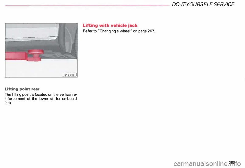
The
lift arms and the floor jack must be ap
plied beneath these points only.
Lifting point front
The lifting point is located on the floor pan
reinforcement about at the same height as
the jack mounting point.
Do not lift the vehicle at the vertical sill rein
forcement.
Page 286 of 306
----------------------DO-IT-YOURSELF SERVICE
Lifting point rear
The lifting point is located on the vertical re
inforcement of the lower sill for on-board
jack. Lifting
with vehicle jack
Refer to "Changing a wheel" on page 267
285
Page 287 of 306
TE
CHNICAL DAT
A-------------------------
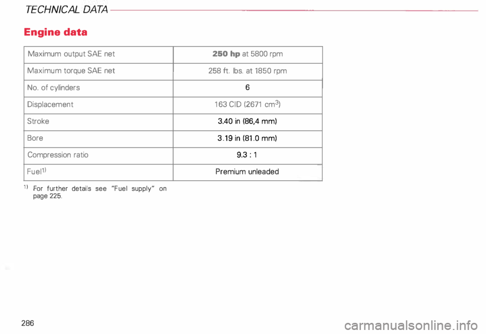
Engine data
Maximum output SAE net
Maximum torque SAE net
No. of cylinders
Displacement
Stroke
Bore Compression ratio
Fuel1l
11 For further details see "Fuel supply" on
page 225.
286 250
hp at 5800 rpm
258 ft. lbs. at 1850 rpm
6
16 3 CID (2671 cm3)
3.40 in (86,4 mm)
3.19 in (81 .0 mm)
9.3 : 1
Premium unleaded
Page 288 of 306
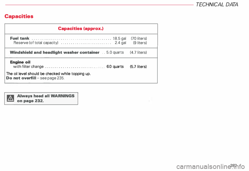
Capacities
Capacities (approx.)
Fuel tank
••••••• •••••••••• ••••••••••••••••• 0 ••• 0 ••
18.5 gal
Reserve (of total capacity) ............
..............
2.4 gal
Windshield and headlight washer container ..
5.0 quarts
Engine oil
with filter change .......................... •
The oil level should be checked while topping up.
Do not overf ill -see page 235.
Always head all WA RNINGS
on page 232. .
. 6.0 quarts TECHNICA
L DAT A
(70 liters)
(9 liters)
(4.7 liters)
(5.7 liters)
287
Page 289 of 306
TECHNICAL DAT
A-------------------------
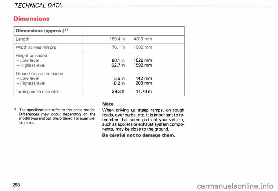
Dimensions
Dimensions (approx.) 1 I
Length
Width across mirrors
Height unloaded
- Low level
- Hig hest level
Ground clearance loaded
- Low level
- Highest level
Tu rning circle diameter
1J The specifications refer to the basic model.
Differences may occur depending on the
model type and options ordered, for example,
tire sizes.
288 18
9.4 in 4810 mm
76.1 in 1932 mm
60.1 in 15
26 mm
62.7 in 15
92 mm
5.6 in 142 mm
8.2 in 208
mm
38.3 ft 11
.70 m
Note
When driving up steep ramps, on rough
roads, over curbs, etc. it is important to re
member that some parts of your vehicle,
such as spoilers or exhaust system compo
nents, may be close to the ground.
Be careful not to damage them.
Page 290 of 306
Weights
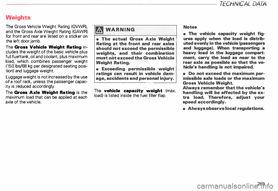
The Gross Vehicle Weight Rating (GVWR),
and the Gross Axle Weight Rating (GAWR)
for front and rear are listed on a sticker on
the left door jamb.
The Gross Vehicle Weight Rating in
cludes the weight of the basic vehicle plus
full fuel tank, oil and coolant, plus maximum
load, which combines passenger weight
(150 lbs/68 kg per designated seating posi
tion) and luggage weight.
Luggage weight is not increased by the use
of a roof rack, unless the passenger capac
ity is reduced accordingly.
The Gross Axle Weight Rating is the
maximum load that can be applied at each
axle of the vehicle. �W
ARNIN G
• The actual Gross Axle Weight
Rating at the front and rear axles
should not exceed the permissible
weights, and their combination
must nbt exceed the Gross Vehicle
Weight Rating.
• Exceeding permissible weight
ratings can result in vehicle dam
age, accidents and personal injury.
The vehicle capacity weight (max.
load) is listed inside the fuel filler flap. TECHNICAL
DATA
Notes
• The vehicle capacity weight fig
ures apply when the load is distrib
uted evenly in the vehicle (passengers
and luggage). When transporting a
heavy load in the luggage compart·
ment, carry the load as near to the
rear axle as possible so that the ve
hicle's handling is not impaired.
• Do not exceed the maximum per
missible axle loads or the maximum
Gross Vehicle Weight.
Always remember that the vehicle's
handling will be affected by the ex
tra load. Therefore, adjust your
speed accordingly.
• Always observe local regulations.
289