AUDI ALLROAD 2000 Owners Manual
Manufacturer: AUDI, Model Year: 2000, Model line: ALLROAD, Model: AUDI ALLROAD 2000Pages: 306, PDF Size: 9.95 MB
Page 271 of 306
DO-IT-Y
OURSELF SERVICE----------------------
\
�W ARNING
Yo u or your passengers could be
injured while changing a wheel if
you do not follow safety precau
tions:
• Jacking at any other place may
damage the vehicle or may result
in personal injuries.
• An unstable surface under the
jack may cause the vehicle to slip
off the jack. Always provide a firm
base for the jack on the ground. If
necessa ry. use a sturdy board un
der the jack.
• On hard. slippery surface (such
as tiles) use a rubber mat or similar
to prevent the jack from slipping.
270 Step
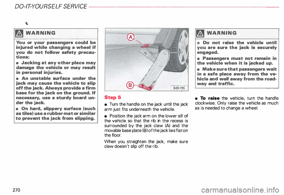
5
• Turn the handle on the jack until the jack
arm just fits underneath the vehicle.
• Position the jack arm on the lower sill of
the vehicle so that the rib in the recess is
surrounded by the jack claw (A) and the
movable base plate (8) of the jack lies flat on
the floor.
When you straighten the jack, make sure
claw doesn't slip off the rib. �W
ARNING
o Do not raise the vehicle until
you are sure the jack is securely
engaged.
• Passengers must not rema in in
the vehicle when it is jacked up.
• Make sure that passengers wait
in a safe place away from the ve
hicle and well away from the road
way and traffic.
• To raise the vehicle, turn the handle
clockwise. Only raise the vehicle as much
as is needed to change a wheel.
Page 272 of 306
----------------------DO-IT-YOURSELF SERVICE
Step &
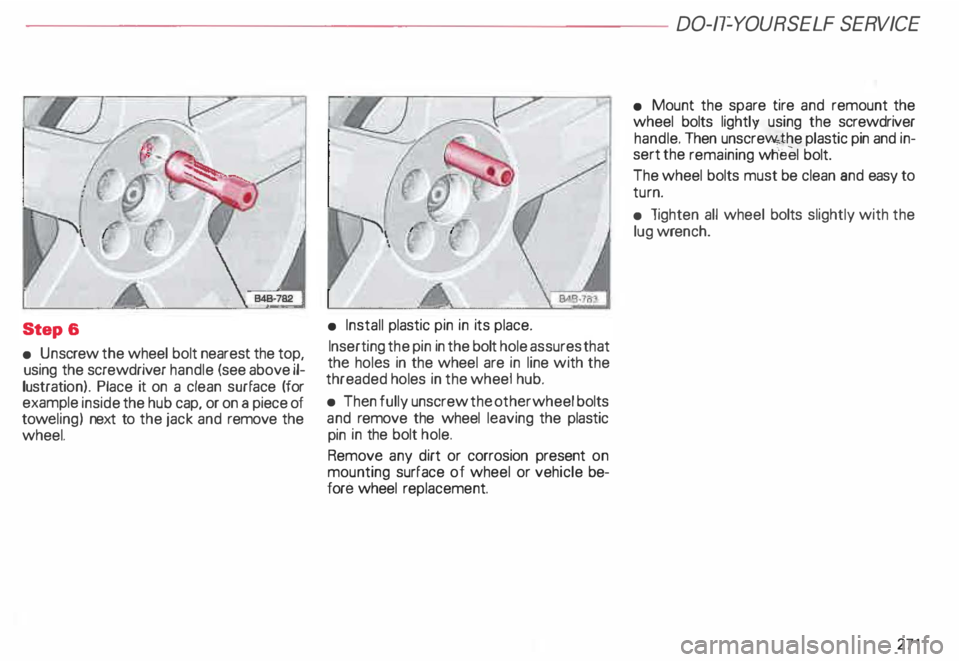
• Un screw the wheel bolt nearest the top,
using the screwdriver handle (see above il
lustratio n). Place it on a clean surface (for
example inside the hub cap, or on a piece of
tow eling) next to the jack and remove the
wheel.
l<:z�
(r.-
• Install plastic pin in its place.
Inserting the pin in the bolt hole assures that
the holes in the wheel are in line with the
threaded holes in the wheel hub.
• Then fully unscrew the other wheel bolts
and remove the wheel leaving the plastic
pin in the bolt hole.
Remove any dirt or corrosion present on
mounting surface of wheel or vehicle be
fore wheel replacement. •
Mount the spare tire and remount the
wheel bolts lightly using the screwdriver
handle. Then unscre�J'o4the plastic pin and in
sert the remaining wheel bolt.
The wheel bolts must be clean and easy to
turn.
• lighten all wheel bolts slightly with the
lug wrench.
271
Page 273 of 306
DO-IT-Y
OURSELF SERVICE----------------------
Step
7
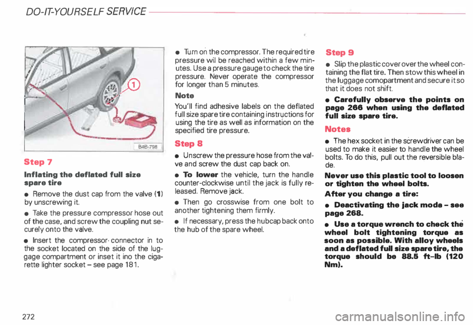
Inflating the deflated full size
spare tire
• Remove the dust cap from the valve (1 l
by unscrewing it.
• Take the pressure compressor hose out
of the case, and screw the coupling nut se
curely onto the valve.
• Insert the compressor· connector in to
the socket located on the side of the lug
gage compartment or inset it ino the ciga
rette lighter socket -see page 181.
272 •
Turn on the compressor. The required tire
pressure wil be reached within a few min
utes. Use a pressure gauge to check the tire
pressure. Never operate the compressor
for longer than 5 minutes.
Note
Yo u'll find adhesive labels on the deflated
full size spare tire containing i nstn .1ctions for
using the tire as well as information on the
specified tire pressure.
Step S
• Un screw the pressure hose from the val
ve and screw the dust cap back on.
• To lower the vehicle, turn the handle
counter-clockwise until the jack is fully re
leased. Remove jack.
• Then go crosswise from one bolt to
another tightening them firmly.
• If necessary, press the hubcap back onto
the hub of the spare wheel. Step
9
• Slip the plastic cover over the wheel con
taining the flat tire. Then stow this wheel in
the luggage comopartment and secure it so
that it does not shift.
• Carefully observe the points on
page 288 when using the deflated
full size spare tire.
Notes
• The hex socket in the screwdriver can be
used to make it easier to handle the wheel
bolts. To do this, pull out the revers ible bla-
de. ·
Never use this plastic tool to loosen
or tighten the wheel bolts.
After you change a tire:
• Deactivating the jack moda -see
page 268.
• Use a torque wrench to check the
wheel bolt tightening torque as
soon as possible. With alloy wheels
and a deflated full size spare tire, the
torque should be 88.5 ft-lb (120
Nm).
Page 274 of 306
•
Be sure to check the tire pressure
as quickly as possible after you
install a wheal that is fitted with
new tires.
If you notice while changing a tire
that the wheal bolts are corroded
and difficult to turn, then they
should be replaced before you
check the tightening torque.
Until then, drive with extra care and
at reduced speeds. m
WARNING
• If you are going to equip your ve
hicle with tires or rims which dif
fer from those which were factory
installed, then be sure to read the
information on page 257.
• Always store damaged wheel,
jack and tools securely in luggage
compartment. DO-IT-YO
URSELF SERVICE
Note
Remember that the deflated full size
spare tire is for temporary use only!
273
Page 275 of 306
DO-IT-YOURSELF
SERVICE----------------------
Fuses
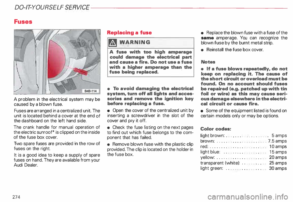
A problem in the electrical system may be
caused by a blown fuse.
Fuses are arranged in a centra lized unit. The
unit is located behind a cover at the end of
the dash board on the left hand side.
The crank handle for manual operation of
the electric sunroof* is cli pped on the inside
of the fuse box cover.
Two spare fuses are provided in the row of
fuses on the right.
It is a good idea to keep a supply of spare
fuses on hand. They are available from your
Audi Dealer.
274 Replacing
a fuse
� WARNING
A fuse with too high amperage
could damage the electrical part
and cause a fire. Do not use a fuse
with a higher amperage than the
fuse being replaced. ·
• To avoid damaging the electrical
system. turn off all lights and acces
sories and remove the ignition key
before replacing a fuse.
• Open the cover of the centralized unit by
inserting a screwdriver in the slot of the
cover and pry it off.
• Check the fuse listing on the next pages
to find out which fuse belongs to the com
ponent that has failed.
• Remove blown fuse with the plastic clip
prov ided. The clip is located on the holder in
the fuse box. •
Replace the blown fuse with a fuse of the
same amperage. You can recognize the
blown fuse by the burnt metal strip.
• Reinstall the fuse box cover.
Notes
• If a fuse blows repeatedly. do not
keep on replacing it. The cause of
the short circuit or overload must be
found. On no account should fuses
be repaired (e.g. patched up with tin
foil or wire) as this may cause seri
ous damage elsewhere in the electri
cal circuit or cause fire.
• Some of the equipment listed is found on
certa in models only or may be options.
Color codes:
light brown: . .
... • _ .. .. . __ . _ . 5 amps
brown: .... .
red: ....... .
light blue: ..
yellow: .....
transparent (white): ..•
light green: .. _
7.5 amps
10 amps
15 amps
20 amps
25 amps
30 amps
Page 276 of 306

Fuse
arrangement
No. 1 - Heated washer jets !
B45-087C I
A 11
- .. 5
2 - Turn signals . . . . . . . . .
. 10
3 - Headlight washer (relay)
illum ination for glove compartment,
climate control, Automatic
Tr ansmission, instrument cluster ... 5
4 - License plate light . . . 5
l) Amps No.
A1l
5 - Ins trument cluster, seat heating,
test connection for cruise control,
bulb monitor, Automatic
Tr ansmis sion display, switch lighting,
mirror switches and actuators,
airbag warning light, outside
temperature indicator, climate
control, solar roof, acoustic parking
assistance system, navigation
system, car telephone, 4 Level Air
Suspension ............ .. ...... 1 0
6 - Power locking system . . . . . . . . . 5
7 - Anti-lock brake system (ABS),
brake light switch . . . . . . . . . . . . 1 0
8 - Car telephone . . . . . . . . . . . . . . .
. 5
9 - Heated mirrors . . . . . . . . . . . . . . 1 0
1 0- Automatic headlight adjustment
. 5
11 -Cruise control
(Automatic Transmission) . . .
1 0
12- On Board Diagnostic system .... _ 10
13 -Brake lights . . . . . . 1 0 DO-IT-YOURSELF
SERVICE
No. 14 -Interior lights, reading lights,
anti-theft alarm system,
vanity mirror, seat memory ....... 10
15 -Instrument cluster, climate control,
mirror and seat mem ory, .
navigation system . . . . . . . . . . . . . . 1 0
16- Electronic Stability Programm ..... 5
17 -Navigation system, 4 Level Air
Suspension, automatic headlight
adjustment .............. ...... 10
18-Hig h-beam, right ......... ....... 10
19 -H igh-beam, left . . . . . . . . . . . . .. 1 0
20 � Low beam, right, headlight
adjustment . . . . . . . . . . . . . . . • . .
15
21 -Low beam, left, headlight
adjustment . . . . . . . . . . . . . . . .. 15
22 -Side marker and tail light, right . 5
23 -Side marker and tail light, left . . . . . 5
24 -Wiper and washer system . . 25
25 -Blower for heating (climate
control), solar roof 30
275
Page 277 of 306
DO-IT-YOURSELF
SERVICE----------------------
No.
A11 No.
A 11 Automatic
circuit breakers
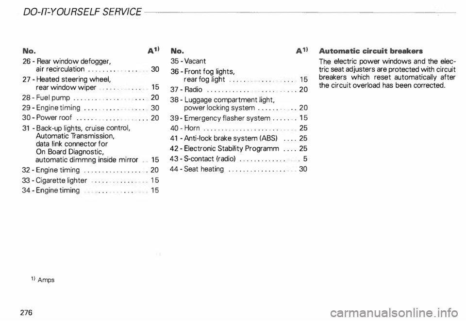
26 -Rear window defogger,
air recirculation . . . . . . . .
30
27 -Heated steering wheel,
rear window wiper , . . . . . 15
28 -Fuel pump . . . . . . . , . . . . 20
29 - Engine timing . . . . . . . . . .
30
30 -Power roof . . . . . .
. ... 20
31 -Back-up lights, cruise control,
Automatic Transmission,
data link connector for
On Board Diagnostic,
automatic dimmng inside mirror
15
32 -Engine timing . . . . . . . . . . . . . . . . . 20
33 -Ciga rette lighter 15
34 - Engine timing
1l Amps
276 15 35
-Va cant
36 -Front fog lights,
rear fog light ...... .
37 -Radio ........... .
38 - Luggage compartment light, . . .
15
. . ... 20
power locking system . . . . . . . . . . 20
39 -Emergency flasher system ....... 15
40 -Horn . . . . . . . . . . . . . . . . . . . . . . . 25
41 -Anti-lock brake system (ABS) .. .. 25
42 -Electronic Stability Programm .... 25
43 -$-contact (radio) . . . . . . . . . . . . . . 5
44 -Seat heating . ... ... . ... ... ..... 30 The
electric power windows and the elec
tric seat adjusters are protected with circuit
breakers which reset automatically after
the circuit overload has been correcte d.
Page 278 of 306
----------------------DO-IT-YOURSELF SERVICE
Replacing bulbs
It is becoming increasingly more and more
difficult to replace vehicle light bulbs since
in many cases, other parts of the car must
first be removed before you are able to get
to the bulb. This applies especially to the
light bulbs in the front of your car which you
can only reach through the engine compart
ment.
For your safety, we recommend that you
have your authorized Audi Dealer replace
any bulbs for you, since your dealer has nec
essary tools, the correct bulbs and the ex
pertise.
g Always heed all WARNINGS
� on page 232. Gas
discharge lamps
(Xenon lights)•
Yo ur vehicle may be equipped with gas dis
charge lamps. Due to the high elec trical
voltage, have the bulbs exchanged by a
qualified technician.
Headlights with xenon light are identified by
the high voltage sticker(see symbol above).
� WARNING
Only your authorized Audi Dealer
or a qualified workshop should
change the bulbs in gas discharge
lamps (xenon light). Due to the
high voltage, improper handling
can cause serious personal injury. Insta
lling I
replacing a radio
f you wish to install a radio or replace the
factory installed radio, please note the fol
lowing:
• The factory installed radio connectors are
designed for Genuine Audi Radios.
When installing a different radio, difficulties
could arise such as:
- the radio may not fit into the space pro
vided
- the electrical connections may not be
compat ible
- different connector terminals may be
needed.
• Therefore, we recommend that you have
your authorized Audi Dealer install or re
place the radiO.
They are the most familiar with the techni
cal features of your vehicle. They also offer
Genuine Audi Radios with the necessary
installation components and instructions.
� WARNING
Improperly installing a radio could
cause a short circuit.
This could result in an electrical
fire.
277
Page 279 of 306
DO-IT-Y
OURSELF SERVICE----------------------
Emergency starting
Note
Starting by pushing or towing
Yo ur vehicle with automatic trans
mission cannot be started by push
ing or towing.
Star ting with jumper cables
�W ARNING
• Batteries contain electricity.
acid. and gas. Any of these can
cause vary serious or fatal injury.
Follow the instructions below for
safe handling of your vahicle"s bat·
tery.
• Always shield your ayes and
avoid leaning over the battery
whenever possible.
278 �,
WAR NING continued
• A discharged battery can al
ready freeze at temperatures just
below 32 °F (0 °C). Before connect·
ing a jumper cable. the frozen bat
tery must be thawed completely.
otherwise it could explode.
• Do not allow battery acid to con·
tact ayes or skin. Flush any con
tacted area with water immediate
ly.
• Improper use of a booster bat
tery to start a vehicle may cause an
explosion.
• Vehicle batteries generate ex
plosive gases. Keep sparks. flame
and lighted cigarettes away from
batteries.
• Do not try to jump start any ve
hicle with a low acid level in the
battery. ,Al
WARNING continued
• The voltage of the booster bat
tery must also have a 12- Volt rat
ing.
The capacity (Ah) of the booster
battery should not be lower than
that of the discharged battery. Use
of batteries of different voltage or
substantially different Ah rating
may cause an explosion and per
sonal injur y.
• Use of batteries of different
voltage or substantially different
amp. (Ah) rating may causa an ex
plosion and Injury. The capacity
(Ah) of the booster battery should
not be lower than that of the dis
charged battery.
Page 280 of 306
----------------------DO-IT-YOURSELF SERVICE
Note
• Applying a higher voltage booster
battery will cause expensive dam
age to sensitive electronic compo
nents, such as control units, relays,
radio, etc.
• Ve hicle with discharged battery:
Turn off lights and accessories, move lever
of automatic transmission to N (Neutral)
or P (Park) and set parking brake. Use
of jumper cables
�W ARNING
• To avoid serious personal Injury
and damage to the vehicle, heed
all warnings and instructions of
the jumper cable manufacturer.
If in doubt, call for road service.
• The jumper cables must be long
enough so that the vehicles do not
touch.
• When
connecting jumper
cables, make sure that they cannot
get caught in any moving parts in
the engine compartment. Removing
the battery cover -see
page 245.
Improper hook-up of jumper cables
can ruin the generator.
Always connect POSITIVE (+ ) to
POSITIVE (+ ). and NEGATIVE (-)to
NEGATIVE (-).
279