ECU AUDI Q2 2021 Owner´s Manual
[x] Cancel search | Manufacturer: AUDI, Model Year: 2021, Model line: Q2, Model: AUDI Q2 2021Pages: 364, PDF Size: 87.77 MB
Page 11 of 364
- How can I call up information online?
^>page
191, Audi connect (infotainment).
- How can I use the Wi-Fi hotspot?
•=>page
201.
Navigation
- What ways are there to enter
a
navigation des
tination?
^>page
208.
- How do I operate the map functions?
•=>
page 219.
- How can I display traffic information?
=>
page 225.
Entertainment
- How can I listen to the radio?
^>page
228.
- How can I play media?
^page
243.
- How can I play music from my mobile phone via
the
infotainment
system?
•=>page
237, Blue
tooth audio
player.
Tips and tricks
- How can I unlock my vehicle from inside to let
passengers in?
=t>page
40.
- How can I open all the windows from outside
using the remote control key?
•=>page
47,
Convenience
open/close function.
- How can I operate both sides of the air condi
tioner together?
^page
69.
- How can I deactivate the front passenger's air-
bag?
•=>
page 288.
- How do I secure a child seat?
^>page
270.
- What do I have to be aware of when driving
through an automatic car wash?
<$page
312.
- How can I drive (more) economically?
^>page
72.
- How can I see when the next service date is?
^page
304.
Page 22 of 364
Instruments and controls
-Totaljourney
memory summary
- Energy consumers
^>page
20
- Driver assistance
^>page
104
- Traffic sign recognition
<=>page
108
The single journey memory processes the infor
mation on
a
journey from the time the ignition is
switched on until it is switched off. If the journey
is resumed within two hours after the ignition is
switched off, the new figures are automatically
included in the calculation.
Unlike the
single
journey memory, the totaljour-
ney memory is not erased automatically. In this
way, you can determine the period for which you
wish the on-board computer to supply driving in
formation.
Fuel consumption
The current fuel consumption can be shown in a
bar display
^>Fig.
15. The average fuel consump
tion from the single journey memory can also be
displayed.
If the barturns green, yourvehicle is
saving fuel using the following function:
- Recuperation: Electrical energy can be stored in
the battery (recuperation) if the vehicle is trav
elling downhill or coasting in gear (overrun). In
this case, the bar will move towards the
Q
symbol.
- Active Cylinder Management*: The engine au
tomatically shuts down two cylinders when per
formance demand is low and certain other
con
ditions have been met. This process is imper
ceptible to the occupants. The driver message
2-cylinder
mode will appear if the average fuel
consumption display
^>Fig.
15 is selected in the
instrument cluster. The cylinders are reactiva
ted under heavier load conditions.
Energy consumers*
In the Energy consumers view, auxiliary equip
ment currently affecting the vehicle's fuel
con
sumption is listed. The display shows up to
three energy consumers. The energy consumer
drawing the most power appears at the top of
the list. If more than three energy consumers are
switched on, the ones currently using the most
power are displayed. In addition, a scale
indi
cates the overall current fuel consumption of all
energy consumers.
Economy tips
Applies to: vehicles with Audi drive select and efficiency mode
In efficiency mode, economy tips are shown
briefly on the instrument cluster display in cer
tain situations where fuel economy is affected.
By following these economy tips, you can save
fuel.
To clear an economy tip from the display immedi
ately, press the left thumbwheel on the multi
function steering wheel.
To activate/deactivate economy
tips:
Select the
following on the infotainment system:
|MENU|
button > Car
>
Audi drive select. Select: efficien
cy
>
right control button > Economy tips.
© Note
- The date, the time and the time/date dis
play format can be changed via the infotain
ment system
^page
255.
- The economy tips are not always displayed
in every conceivable situation, but are delib
erately spaced out over time.
- Once you have cleared an economy tip from
the display, it will not appear again until the
next time you switch on the ignition.
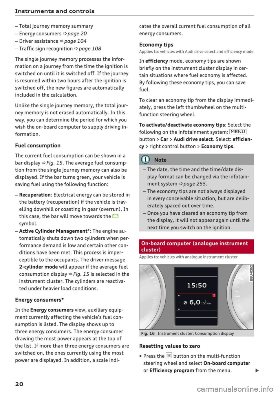
On-board computer (analogue instrument
cluster)
Applies to: vehicles with analogue instrument cluster
15:50
0
6,0
Fig.
16 Instrument cluster: Consumption display
Resetting values to zero
•
Press the
[Hi
button on the multi-function
steering wheel and select On-board computer
or Efficiency program from the menu. •
20
Page 61 of 364
Seats and storage
• To lower the head restraint, press the side but
ton and slide the head restraint downwards.
A WARNING
Please observe the safety warnings
^>page
266, Correct adjustment of head re
straints.
r,
IN
:
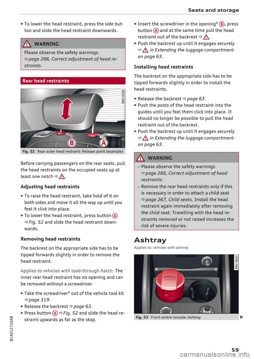
B
Fig.
52 Rear outer head restraint: Release point (example)
Before carrying passengers on the rear seats, pull
the head restraints on the occupied seats up at
least one notch
oA.
Adjusting head restraints
• To raise the head restraint, take hold of it on
both sides and move it all the way up until you
feel it click into place.
• To Lower the head restraint, press button
(A)
^>Fig.
52 and slide the head restraint
down
wards.
Removing head restraints
The backrest on the appropriate side has to be
tipped forwards slightly in order to remove the
head restraint.
Applies to vehicles with load-through hatch: The
inner rear head restraint has no opening and can
be removed without a screwdriver.
• Take the screwdriver* out of the vehicle tool kit
•=>
page 319.
• Release the backrest
opoge
63.
• Press button
(A)
^>Fig.
52 and slide the head re
straint upwards as far as the stop.
• Insert the screwdriver in the opening* (J), press
button
(A)
and at the same time pull the head
restraint out of the backrest
<=> /\.
• Push the backrest up until it engages securely
•=> /\
in Extending the luggage compartment
on page 63.
Installing head restraints
The backrest on the appropriate side has to be
tipped forwards slightly in order to install the
head restraints.
• Release the backrest
^>page
63.
• Push the posts of the head restraint into the
guides until you feel them click into place. It
should no Longer be possible to pull the head
restraint out of the backrest.
• Push the backrest up until it engages securely
•=> /\
in Extending the luggage compartment
on page 63.
A WARNING
- Please observe the safety warnings
^page
266, Correct adjustment of head
restraints.
- Remove the rear head restraints only if this
is necessary in order to attach a child seat
^>page
267, Child seats. InstaLl the head
restraint again immediately after removing
the child seat. Travelling with the head re
straints removed or not raised increases the
risk of severe injuries.
Ashtray
Applies to: vehicles with ashtray
~
-
a»
rS
Fig.
53 Front centre console: Ashtray
59
Page 63 of 364
Seats and storage
CO
rN
•-i
00
children unsupervised in the vehicle with the
key.
© CAUTION
- To avoid damage, please take care when de
taching connectors from the electrical pow
er sources.
-To avoid damage to the vehicle's electrical
system,
never connect equipment that
gen
erates electrical current, such as a solar
panel or battery charger, to the power sour
ces in order to charge the vehicle's battery.
- Always use the correct type of plugs to
avoid damaging the power sources.
©
USB charging sockets marked "CHARGE ON
LY" cannot transfer data and are intended for
charging only.
Storage
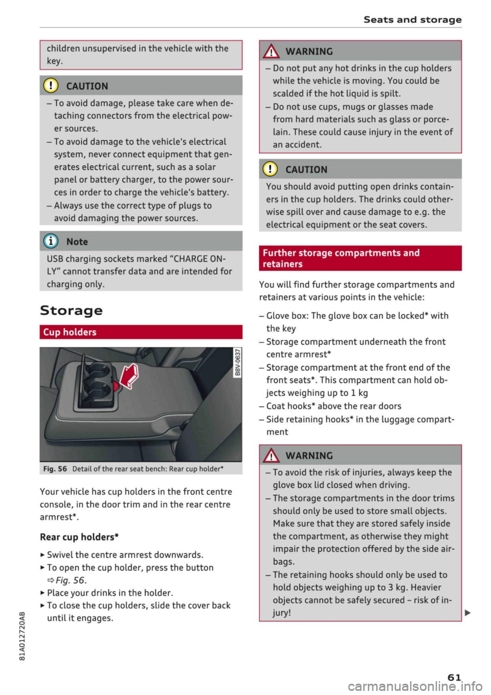
Cup holders
/
Fig.
56
BfT
^^—- j
^^ m /
Detail of the rear seat bench: Rear cup holder*
r^
n
co
3
>
CO
m
A
Your vehicle has cup holders in the front centre
console, in the door trim and in the rear centre
armrest*.
Rear cup holders*
• Swivel the centre armrest downwards.
• To open the cup holder, press the button
•=>
Fig.
56.
• Place your drinks in the holder.
• To close the cup holders, sLide the cover back
until it engages.
A WARNING
- Do not put any hot drinks in the cup holders
while the vehicle is moving. You could be
scalded if the hot liquid is spilt.
- Do not use cups, mugs or glasses made
from hard materials such as glass or porce
lain.
These could cause injury in the event of
an accident.
© CAUTION
You should avoid putting open drinks contain
ers in the cup holders. The drinks could other
wise spill over and cause damage to e.g. the
electrical equipment or the seat covers.
Further storage compartments and
retainers
You will find further storage compartments and
retainers at various points in the vehicle:
- Glove box: The glove box can be Locked* with
the key
- Storage compartment underneath the front
centre armrest*
- Storage compartment at the front end of the
front seats*. This compartment can hold ob
jects weighing up to 1 kg
- Coat hooks* above the rear doors
- Side retaining hooks* in the luggage compart
ment
A WARNING
- To avoid the risk of injuries, always keep the
glove box Lid closed when driving.
- The storage compartments in the door trims
should only be used to store small objects.
Make sure that they are stored safely inside
the compartment, as otherwise they might
impair the protection offered by the side air-
bags.
- The retaining hooks should only be used to
hold objects weighing up to 3 kg. Heavier
objects cannot be safely secured - risk of in
jury!
61
Page 65 of 364
Seats and storage
CO
<
O
rN
rN
•-i
00
• Use the fastening rings to secure the load
-arrows-.
• Please refer to the safety notes
^page
273.
Stretch net/storage net
Applies to: vehicles with stretch net/storage net
The
stretch net can be used to secure and hold
light items in the luggage compartment.
ri
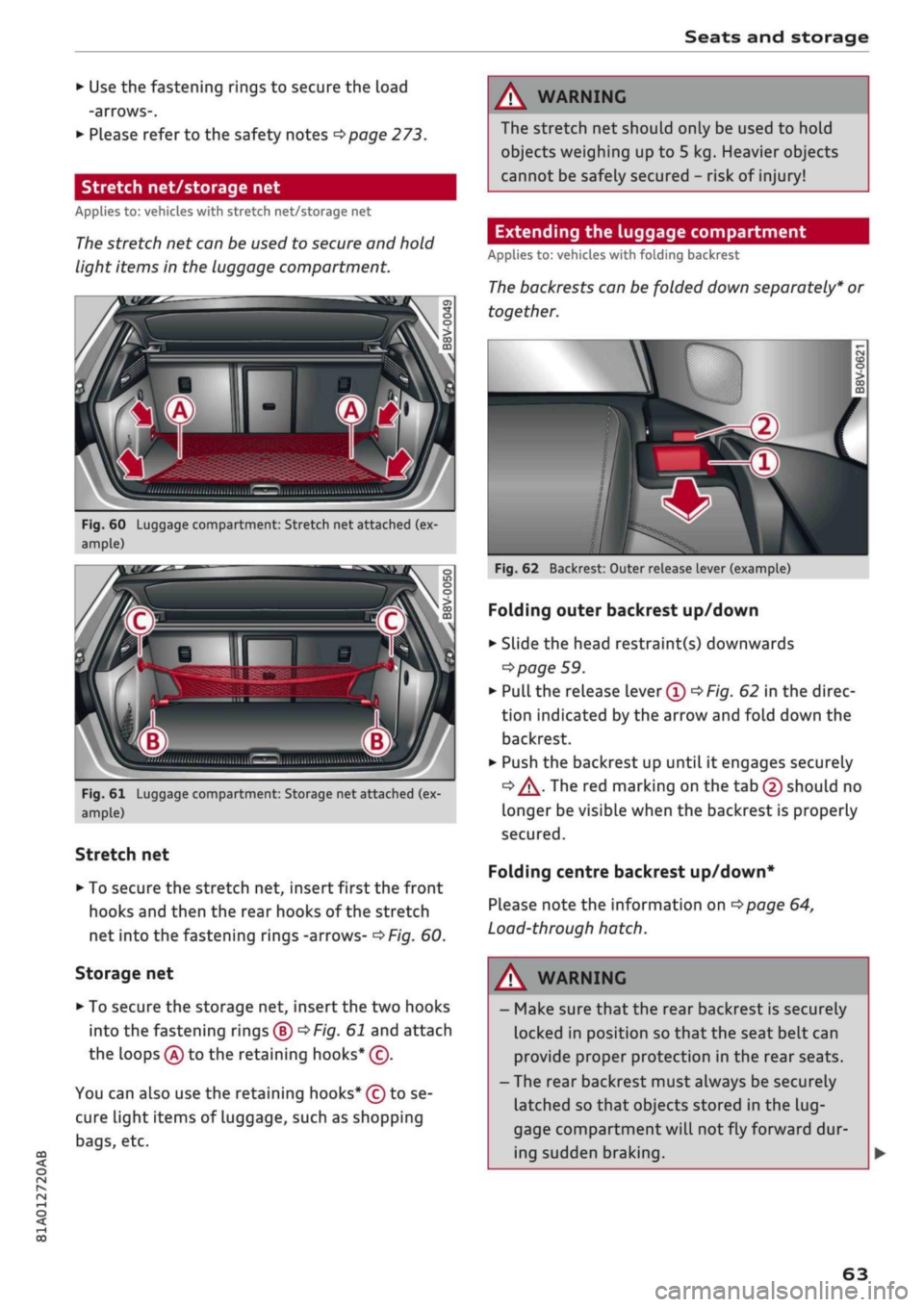
Fig.
60 Luggage compartment: Stretch net attached (ex
ample)
A
Q
"
Fig.
61 Luggage compartment: Storage net attached (ex
ample)
Stretch net
• To secure the stretch net, insert first the front
hooks and then the rear hooks of the stretch
net into the fastening rings -arrows-
^>Fig.
60.
Storage net
• To secure the storage net, insert the two hooks
into the fastening rings®
^F/g.
61 and attach
the loops
(A)
to the retaining hooks* (c).
You can also use the retaining hooks* (ç) to se
cure light items of luggage, such as shopping
bags,
etc.
A WARNING
The stretch net should only be used to hold
objects weighing up to 5 kg. Heavier objects
cannot be safely secured - risk of injury!
Extending the luggage compartment
Applies to: vehicles with folding backrest
The
backrests can be folded down separately* or
together.
\v
Fig.
62 Backrest: Outer release lever (example)
Folding outer backrest up/down
• Slide the head restraint(s) downwards
=>
page 59.
•
Pull
the release lever®
^Fig.
62 in the direc
tion indicated by the arrow and fold down the
backrest.
• Push the backrest up until it engages securely
<=» A-
The red marking on the tab (2) should no
Longer be visible when the backrest is properly
secured.
Folding centre backrest
up/down*
Please note the information on
^>page
64,
Load-through hatch.
WARNING
- Make sure that the rear backrest is securely
locked in position so that the seat belt can
provide proper protection in the rear seats.
- The rear backrest must always be securely
latched so that objects stored in the
lug
gage compartment will
not
fly forward dur
ing sudden braking.
63
Page 66 of 364
Seats and storage
© CAUTIOI
- If
you
need to adjust the front seats when
either of the rear backrests is folded for
wards, please take care to avoid damaging
the rear head restraints. If necessary, re
move the appropriate head restraints be
fore you slide back the front seats.
- Lower the rear head restraints before you
fold down the backrest
•=>
A in Rear head
restraints on page 59 - risk of damage!
- When returning the backrest to an upright
position,
make sure that the seat belts for
the outer rear seats are not caught up and
damaged in the catches for the backrest.
Load-through hatch
Applies to: vehicles with load-through hatch
ft
•
/ Bsa-1
j^^V^il
n^B
iV^yM
•
in
H o
• CD •
O
• >
CO
CD
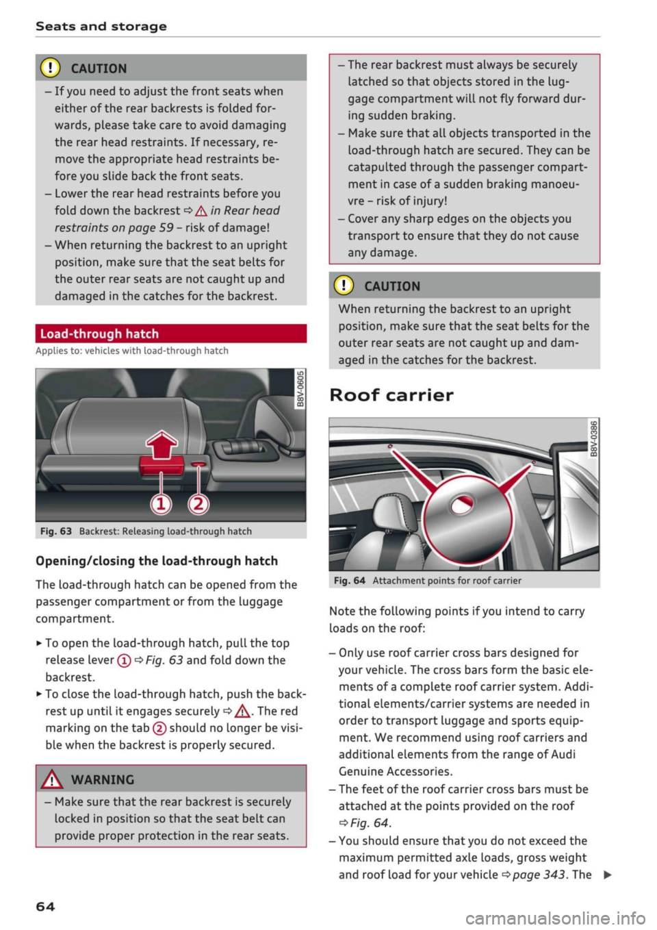
Fig.
63 Backrest: Releasing load-through hatch
Opening/closing the load-through hatch
The
Load-through
hatch can be opened from the
passenger compartment or from the luggage
compartment.
• To open the load-through hatch, pull the top
release lever®
OF/g.
63 and fold down the
backrest.
• To close the load-through hatch, push the
back
rest up until it engages securely
d>^.
The red
marking on the tab (2) should no longer be
visi
ble when the backrest is properly secured.
A WARNING
- Make sure that the rear backrest is securely
locked in position so that the seat belt can
provide proper protection in the rear seats.
- The rear backrest must always be securely
latched so that objects stored in the
lug
gage compartment
wilL
not fly forward dur
ing sudden braking.
- Make sure that all objects transported in the
Load-through
hatch are secured. They can be
catapulted through the passenger compart
ment in case of
a
sudden braking manoeu
vre - risk of injury!
- Cover any sharp edges on the objects you
transport to ensure that they do not cause
any damage.
© CAUTION
When returning the backrest to an upright
position,
make sure that the seat belts for the
outer rear seats are not caught up and dam
aged in the catches for the backrest.
Roof carrier
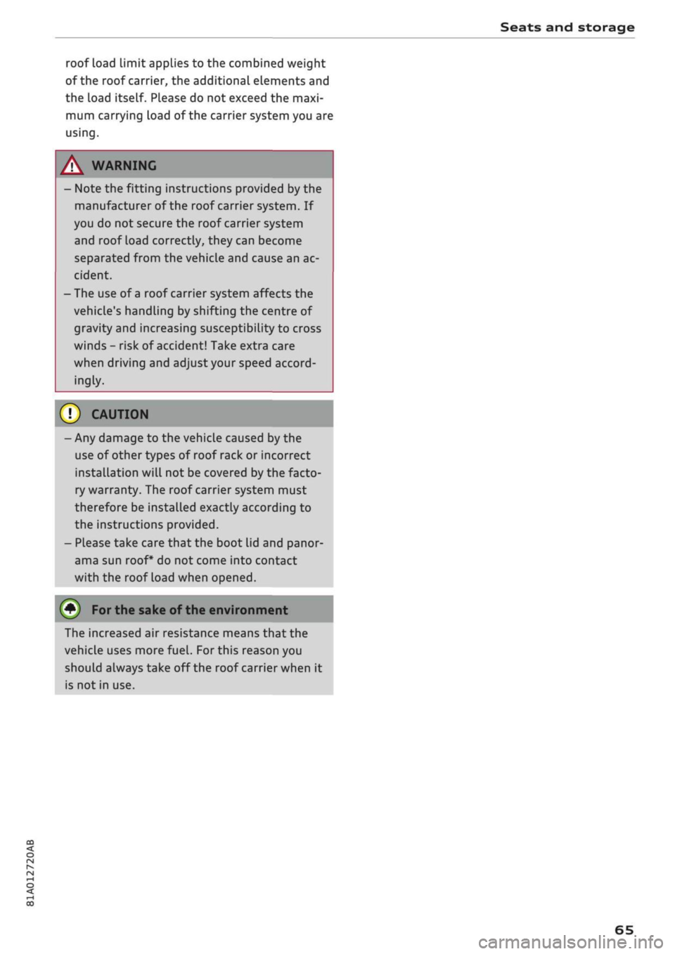
Fig.
64 Attachment points for roof carrier
Note the folLowing points if
you
intend to carry
loads on the roof:
- Only use roof carrier cross bars designed for
your vehicle. The cross bars form the basic ele
ments of
a
complete roof carrier system. Addi
tional elements/carrier systems are needed in
order to transport luggage and sports equip
ment. We recommend using roof carriers and
additional elements from the range of Audi
Genuine Accessories.
- The feet of the roof carrier cross bars must be
attached at the points provided on the roof
*>Fig.
64.
- You should ensure that you do not exceed the
maximum permitted axle loads, gross weight
and roof load
for
your vehicle
•=>page
343. The
64
Page 67 of 364
Seats and storage
CO
rN
rN
•-i
00
roof load limit applies to the combined weight
of the roof carrier, the additional elements and
the Load itself. Please do not exceed the maxi
mum carrying load of the carrier system you are
using.
A WARNIN
- Note the fitting instructions provided by the
manufacturer of the roof carrier system. If
you do not secure the roof carrier system
and roof load correctly, they can become
separated from the vehicle and cause an ac
cident.
- The use of
a
roof carrier system affects the
vehicle's handling by shifting the centre of
gravity and increasing susceptibility to cross
winds - risk of accident! Take extra care
when driving and adjust your speed accord
ingly.
CAUTION
- Any damage to the vehicle caused by the
use of other types of roof rack or incorrect
installation will not be covered by the facto
ry warranty. The roof carrier system must
therefore be installed exactly according to
the instructions provided.
- Please take care that the boot lid and panor
ama sun roof* do not come into contact
with the roof load when opened.
(•)
For
the sake of the environment
The increased air resistance means that the
vehicle uses more
fuel.
For this reason you
should always take off the roof carrier when it
is not in use.
65
Page 76 of 364

Driving
Steering
Adjusting the steering wheel position
The height and reach of the steering wheel can
be adjusted as required to suit the
driver.
Fig.
68 Steering column: Lever for steering column adjust
ment
•
Push the Lever
^>Fig.
68 down
<=> /\.
•
Move the steering wheel to the desired
posi
tion.
•
Then push the lever towards the steering
col
umn until the catch engages.
WARNING
- Never adjust the position of the steering
wheel when the vehicle is moving - this
could cause an accident.
- Press the lever upwards so it is secure and
so that the position of the steering wheel
cannot shift unexpectedly while the vehicle
is moving - risk of accident!
Starting and stopping
the engine (vehicles with
ignition Lock)
Starting the engine
Applies to: vehicles with ignition lock
Insert the key in the ignition lock to switch on
the ignition and start the engine.
Fig.
69 Ignition lock: Ignition key positions
Switching the ignition on/off
•
To switch on the ignition, turn the ignition key
to position ®. Vehicles without start/stop sys
tem*:
The rev counter needle will move to the
READY position.
• To switch off the ignition, turn the ignition key
to position ©. The rev counter needle will
move to the OFF position.
Diesel engines are automatically preheated when
you switch on the ignition.
Starting the engine
•
Manual gearbox: Press the clutch pedal all the
way down and move the gear lever into neutral.
•
Automatic gearbox: Press the brake pedal and
move the selector lever to position P or N.
•
Turn the ignition key briefly to position @. The
ignition key automatically returns to position
®. Do not press the accelerator.
Applies to: vehicles with diesel engine
•
The engine may take a few seconds Longer than
usual to start on cold days. Please keep your
foot on the clutch pedal (manual gearbox) or
brake pedal (automatic gearbox) until the en
gine starts. The indicator Lamp
E g
lights up
while the glow plugs are preheating.
74
Page 98 of 364
Towing a trailer
Towing a trailer
Driving the vehicle with a
trailer or caravan
Technical requirements
The
towing bracket must comply with certain
technical requirements.
Your car is intended mainly for transporting pas
sengers and luggage. However, if suitably equip
ped,
it can also be used to tow a trailer or cara
van.
If the car is supplied with a factory-fitted towing
bracket it will already have the necessary techni
cal modifications and meet the statutory require
ments.
A 13-pin socket is provided to make the electrical
connection between the car and the trailer. If the
trailer you wish to tow has a 7-pin plug, the nec
essary adapter cable can be obtained from a spe
cialist retailer.
If
a
towing bracket is to be fitted after the car is
purchased,
this must be done according to the in
structions of the towing bracket manufacturer
^page
102.
A WARNING
If
a
towing bracket is retrofitted, the installa
tion should be carried out by
a
qualified work
shop.
- In particular in high outside temperatures it
is not possible to drive up long steep gradi
ents without
a
suitable cooling system. The
engine would then overheat.
- Incorrect installation can result in a safety
risk.
Points to check before towing
There are a number of points which need to be
checked before towing a trailer or caravan.
*•
Observe the maximum permitted trailer
weights
^>page
342.
Trailer weights
Never exceed the maximum permitted trailer
weights.
If
you
do not load the trailer up to the maximum
permitted trailer weight, you can then climb cor
respondingly steeper gradients.
The maximum trailer weights listed are only ap
plicable for altitudes up to 1000 m above sea
level.
With increasing altitude the engine power
and therefore the car's climbing ability are im
paired because of the reduced air density, so the
maximum trailer weight has to be reduced ac
cordingly. The weight of the car and trailer must
be reduced by about 10% for every further
1000 m (or part thereof). This figure refers to
the combined weight of the (loaded) vehicle and
(Loaded) trailer.
The figures for the draw bar weight that appear
on the identification plate of the towing bracket
are for certification purposes only. The correct
figures for your specific model, which may be
lower than these figures for the towing bracket,
are given in the registration documents and in
•=>
page 343.
Drive select*
Please note that the
efficiency*
mode is not
available in towing mode.
Exterior lights
Before starting
a
journey, make sure that all the
lights for the trailer are working properly.
Distributing the load
Distribute loads in the trailer so that heavy ob
jects are as near to the axle as possible. Loads
carried in the trailer must be secured to prevent
them slipping. A badly distributed load can also
affect handling. This can activate the trailer sta
bilisation feature and cause the vehicle to reduce
speed.
Where possible, operate the trailer with the max
imum permitted draw bar weight on the ball
joint of the towing bracket, but do not exceed the
specified limit. •
96
Page 99 of 364
Towing a trailer
Tyre pressure
Check the tyre pressures on your car, and adjust
for "full
load"
conditions (refer to the sticker list
ing the tyre pressures)
^>page
307. It may also
be necessary to adjust the tyre pressures on the
trailer according to the recommendations of the
trailer manufacturer.
Exterior mirrors
Check whether you can see enough of the road
behind the trailer with the standard mirrors. If
this is not the case you should have additional
mirrors fitted. Both exterior mirrors should be
mounted on hinged extension brackets. Adjust
the mirrors to give sufficient vision to the rear.
Headlights
Before starting
a
journey, check the headlight
beam settings with the trailer hitched up. Adjust
the headlight settings if necessary.
On vehicles with halogen headlights, the
head
light range control must be adjusted, see
tapage
49.
The headlight range control will be adjusted au
tomatically if your vehicle is equipped with LED
headlights*.
Power supply
To ensure that the engine can be started again
after the ignition is switched off, the power
man
agement system
^>page
149 controls the distri
bution of electrical power and gradually switches
off unnecessary electrical equipment. The trailer
is supplied with power during this period. The
power supply to the trailer is interrupted while
the engine is being started.
Removable ball joint coupling
Vehicles with a factory-fitted towing bracket are
equipped with a removable
ball
joint coupling.
This is stored in the spare wheel well or in a sepa
rate bag on the floor of the luggage compart
ment, together with the necessary fitting instruc
tions.
We recommend having the car serviced be
tween the normal inspection intervals if it
used frequently for towing a trailer.
Trailer stabilisation system
Applies to: vehicles with towing bracket
Trailer stabilisation helps to reduce the risk of
the vehicle skidding when towing a
trailer.
When is the trailer stabilisation
system1'
activated?
Trailer stabilisation is active when the following
requirements are met:
- The ESC must be switched on
^>page
146 and
fully functional (no ESC malfunction).
- The trailer connector must be properly secured
in the vehicle socket.
- The vehicle speed must be higher than approx.
60 km/h.
How trailer stabilisation works
In many cases, the driver can stabilise a swaying
trailer by manually braking the vehicle.
However, if the ESC detects that the trailer is
swaying and this is affecting the towing vehicle,
it will automatically brake the vehicle in order to
stabilise the trailer. The indicator
Lamp Hi
will
flash in the instrument cluster. If possible, do
not turn the steering wheel at this stage.
In order to warn traffic behind you, the brake
lights will come on during this automatic braking
operation.
A trailer may sway quite considerably without the
trailer stabilisation system intervening.
If the system for activating the trailer brake
lights is defective, this will be indicated in the in
strument cluster display
opage
35,
:&
Bulb
monitor.
•
CO
rN
rN
t-H
o <
x)
Not available on vehicles for some markets.
97