Stop and start AUDI Q2 2021 Owner´s Manual
[x] Cancel search | Manufacturer: AUDI, Model Year: 2021, Model line: Q2, Model: AUDI Q2 2021Pages: 364, PDF Size: 87.77 MB
Page 4 of 364
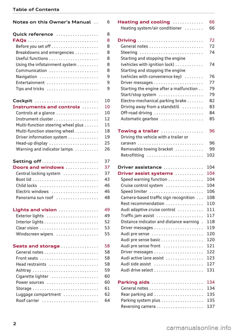
Table of Contents
Notes on this Owner's Manual .. 6
Quick reference 8
FAQs 8
Before you set off 8
Breakdowns and emergencies 8
Useful functions 8
Using the infotainment system 8
Communication 8
Navigation 9
Entertainment 9
Tips and tricks 9
Cockpit 10
Instruments and controls 10
Controls at a glance 10
Instrument cluster 12
Multi-function steering wheel plus 15
Multi-function steering wheel 18
Driver information system 19
Head-up display 25
Warning and indicator lamps 26
Setting off 37
Doors and windows 37
Central locking system 37
Boot lid 43
Child locks 46
Electric windows 46
Panorama sun roof 48
Lights and vision 49
Exterior lights 49
Interior lights 52
Clear vision 53
Windscreen wipers 55
Seats and storage 58
General notes 58
Front seats 58
Head restraints 58
Ashtray 59
Cigarette lighter 60
Power sources 60
Storage 61
Luggage compartment 62
Roof carrier 64
Heating and cooling 66
Heating system/air conditioner 66
Driving 72
General notes 72
Steering 74
Starting and stopping the engine
(vehicles with ignition lock) 74
Starting and stopping the engine
(vehicles with convenience key) 76
Driver messages 77
Starting the engine after a malfunction . . 79
Start/stop system 79
Electro-mechanical parking brake 82
Driving away from a standstill 83
Off-road driving 84
Automatic gearbox 85
Towing a trailer 96
Driving the vehicle with a trailer or
caravan 96
Removable towing bracket 99
Retrofitting 102
Driver assistance 104
Driver assist systems 104
Speed warning function 104
Cruise control system 104
Speed limiter 106
Camera-based traffic sign recognition ... 108
Rest recommendation 110
Audi adaptive cruise control
Ill
Traffic
jam assist 117
Distance indicator and distance warning . 118
Driver messages
119
Audi pre sense 120
Audi pre sense basic 120
Audi pre sense front 121
Driver messages 122
Audi active lane assist 123
Audi side assist 127
Audi drive select 131
Parking aids 134
General notes 134
Rear parking aid
135
Parking system plus 135
Reversing camera 137
2
Page 13 of 364
Instruments and controls
CO
<
o
IV
tN
t-H
o <
(D
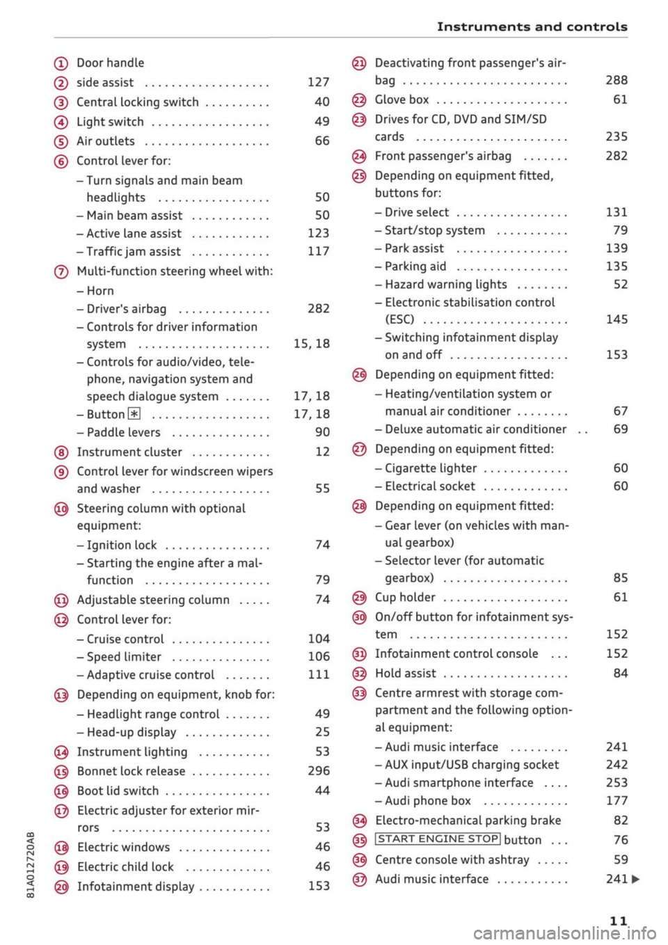
Doorhandle
(D side assist 127
(D CentraL
locking switch 40
@
Light switch 49
(D Air outlets 66
(?) Control lever for:
- Turn signals and main beam
headlights 50
- Main beam assist 50
- Active lane assist 123
-Trafficjam
assist 117
(7) Multi-function steering wheel
with:
- Horn
- Driver's airbag 282
- Controls for driver information
system 15, 18
- Controls for audio/video, tele
phone,
navigation system and
speech dialogue system 17, 18
-ButtonH
17,18
- Paddle levers 90
(5) Instrument cluster 12
(?) Control lever for windscreen wipers
and washer 55
@
Steering column with optional
equipment:
- Ignition lock 74
- Starting the engine after a
mal
function 79
@
Adjustable steering column 74
@
Control lever for:
- Cruise control 104
- Speed limiter 106
-Adaptive cruise control
Ill
@
Depending on equipment, knob for:
- Headlight range control 49
- Head-up display 25
@
Instrument lighting 53
@
Bonnet lock release 296
@
Boot lid switch 44
@
Electric adjuster for exterior mir
rors 53
@
Electric windows 46
@
Electric child lock 46
@
Infotainment display 153
Deactivating front passenger's air-
bag
Glove box
Drives for CD, DVD and
SIM/SD
cards
Front passenger's airbag
Depending on equipment fitted,
buttons for:
- Drive select
- Start/stop system
- Park assist
- Parking aid
- Hazard warning lights
- Electronic stabilisation control
(ESC)
-Switching infotainment display
on and off
Depending on equipment fitted:
- Heating/ventilation system or
manual air conditioner
- Deluxe automatic air conditioner
Depending on equipment fitted:
- Cigarette lighter
- Electrical socket
Depending on equipment fitted:
- Gear lever (on vehicles with
man
ual gearbox)
- Selector lever (for automatic
gearbox)
Cup holder
On/off button for infotainment sys
tem
Infotainment control console ...
Hold assist
Centre armrest with storage com
partment and the following option
al equipment:
- Audi music interface
- AUX input/USB charging socket
- Audi smartphone interface ....
- Audi phone box
Electro-mechanical parking brake
|START
ENGINE STOP] button
Centre console with ashtray
Audi music interface
288
61
235
282
131
79
139
135
52
145
153
67
69
60
60
85
61
152
152
84
241
242
253
177
82
76
59
241
•
11
Page 17 of 364
Instruments
and
controls
CO
<
o
IV
tN
I-I
00
Vehicles with manual gearbox
-
•
Shifting
up
a gear:
The
suggested gear
ap
pears
to the
right
of
the current gear when
a
higher gear
is
recommended.
-
4
Shifting down
a
gear:
The
suggested gear
ap
pears
to the
left
of
the current gear when
a
lower gear
is
recommended.
The gearyou
are
currently
in and the
recommen
ded gear will
be
displayed. Gears
may
occasional
ly
be
skipped
(3 • 5).
Vehicles with start/stop system:
If
all
the
condi
tions
for
a
stop phase
^>page
79
have been
met,
but the
gear lever
is in
gear with
the
clutch
depressed,
the
gear change indicator will recom
mend changing
to
•N.
Put the
gear lever
in
neu
tral and take your foot
off
the clutch pedal.
The
start/stop system will automatically switch
off
the engine.
Vehicles with automatic gearbox
The display
is
only visible
in
tiptronic mode
^>page
90.
The symbol
Î
after
the
current gear means
change
up a
gear.
© CAUTION
The gear-change indicator
is
intended
to
help
save
fuel.
It is not
intended
to
recommend
the right gear
for all
driving situations.
In
cer
tain situations, only
the
driver can choose
the
correct gear
(for
instance when overtaking,
driving
up
a steep gradient
or
towing a
trail
er).
(T) Note
Applies
to:
vehicles with manual gearbox
The gear-change indicator
in the
instrument
cluster goes
out
when you press
the
clutch
pedal.
Outside temperature display
When
the
vehicle
is
stationary
or
travelling
at
very
low
speeds,
the
temperature displayed
may
be slightly higher than
the
actual outside
tem
perature
as
a result
of
the heat radiated from
the
engine.
At temperatures below +5°C a snowflake symbol
appears next
to the
temperature display
<=> A-
A WARNING
Do
not
rely
on the
outside temperature dis
play
as an ice
warning. Bear
in
mind that
there
may be
patches
of
ice
on the
roads even
at outside temperatures around
+5
°C
-
risk
of
accident!
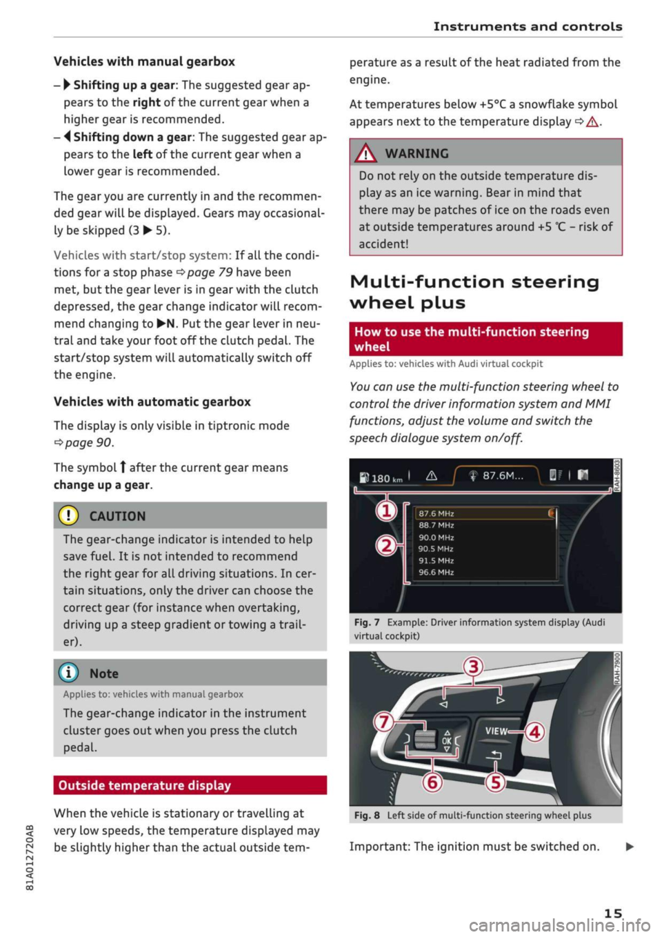
Multi-function steering
wheel plus
How
to use the
multi-function steering
wheel
Applies
to:
vehicles with Audi virtual cockpit
You
can
use
the
multi-function steering wheel
to
control
the
driver information system
and MMI
functions, adjust
the
volume
and
switch
the
speech dialogue system
on/off.
»180km
1
&_J
f
87.6M...
|f
|
H
n
^
_
X
m
®r
87.6 MHz CI /
88.7 MHz
90.0 MHz
90.5
MHz
91.5
MHz
96.6 MHz
Fig.
7
Example: Driver information system display (Audi
virtual cockpit)
In
1-
m
Fig.
8
Left side
of
multi-function steering wheel plus
Important:
The
ignition must
be
switched
on.
15
Page 26 of 364
Instruments and controls
Navigation
Applies to: vehicles with navigation system
Important: The navigation tab must be dis
played.
If route guidance has not been started, the driver
information system display will show
a
compass.
On vehicles with the Audi virtual cockpit*, the
map will be displayed.
•
Press the
HH
button or the left control button
o^page
16, depending on the equipment in
your vehicle.
The following functions are available on the driv
er information system, depending on the vehicle
equipment:
- To call up recent destinations: Select and
con
firm Last destinations > desired destination.
- To call up favourites*: Select and confirm Fa
vourites
>
desired destination.
Applies to: vehicles with analogue instrument cluster
- To display the navigation screen when route
guidance is active: Select and confirm Route
guidance.
- To display the compass when route guidance
is not active: SeLect and confirm Compass.
- To start route guidance to the stored home
address: If applicable, first select and confirm
Stop route guidance, and then select Favour
ites > Home address.
- To cancel the active route guidance: Select and
confirm Stop route guidance.
Applies to: vehicles with Audi virtual cockpit
- To start route guidance to the stored home
address: If applicable, first select and confirm
Stop route guidance, and then select Favour
ites > Home address.
- To cancel the active route guidance: Select
right control button > Stop route guidance.
Other settings
Applies to: vehicles with Audi virtual cockpit
- Select: right control button > desired
entry.
The following settings are available depending
on the equipment on your vehicle and on which
function is selected:
- Map colours
^page
221
- Map orientation
^>page
221
- Automatic zoom
^>page
221
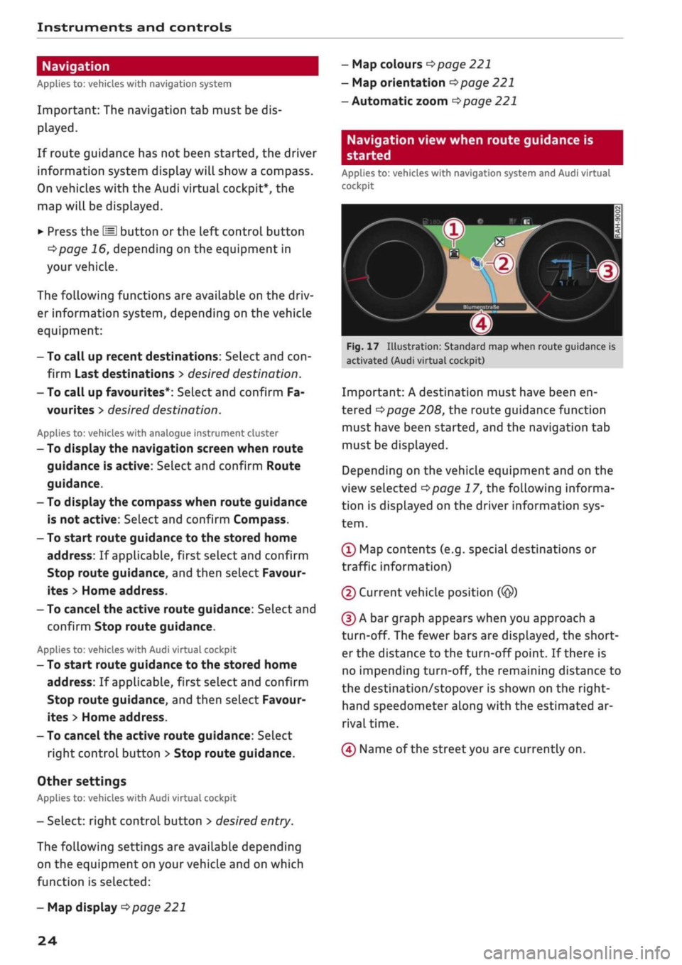
Navigation view when route guidance is
started
Applies to: vehicles with navigation system and Audi virtual
cockpit
1
Fig.
17 Illustration: Standard map when route guidance is
activated (Audi virtual cockpit)
Important: A destination must have been en
tered
Opage
208, the route guidance function
must have been started, and the navigation tab
must be displayed.
Depending on the vehicle equipment and on the
view selected
Opage
17, the following informa
tion is displayed on the driver information sys
tem.
(Ï) Map contents (e.g. special destinations or
traffic information)
(2) Current vehicle position
(@)
(D A bar graph appears when you approach a
turn-off. The fewer bars are displayed, the short
er the distance to the turn-off point. If there is
no impending turn-off, the remaining distance to
the destination/stopover is shown on the right-
hand speedometer along with the estimated ar
rival time.
(4) Name of the street you are currently on.
- Map display
^>page
221
24
Page 27 of 364
Instruments and controls
CO
s
rN rN
I-I
00
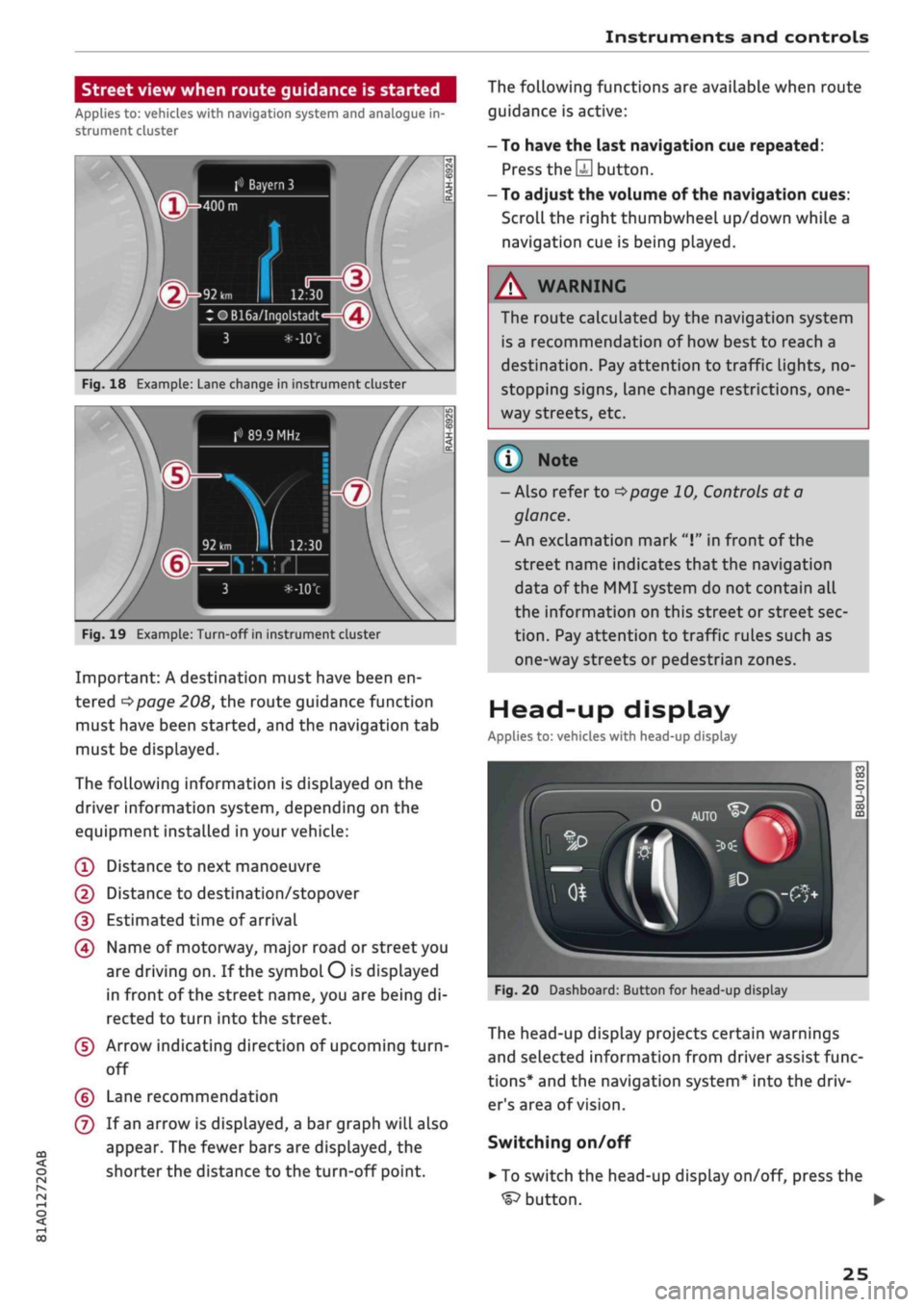
Street view when route guidance is started
Applies to: vehicles with navigation system and analogue in
strument cluster
f»
Bayern
3
:OB16a/Inqolstadt
Fig.
18 Example: Lane change in instrument cluster
> 89.9 MHz
Fig.
19 Example: Turn-off in instrument cluster
Important: A destination must have been en
tered
^>page
208, the route guidance function
must have been started, and the navigation tab
must be displayed.
The following information is displayed on the
driver information system, depending on the
equipment installed in your vehicle:
(T)
Distance to next manoeuvre
@
Distance to destination/stopover
(D Estimated time of arrival
(4) Name of motorway, major road or street you
are driving on. If the symbol
O
is displayed
in front of the street name, you are being di
rected to turn into the street.
(5) Arrow indicating direction of upcoming
turn-
off
(?) Lane recommendation
(7) If an arrow is displayed, a bar graph will also
appear. The fewer bars are displayed, the
shorter the distance to the turn-off point.
The following functions are available when route
guidance is active:
- To have the last navigation cue repeated:
Press
the S
button.
- To adjust the volume of the navigation cues:
Scroll the right thumbwheel up/down while a
navigation cue is being played.
A
WARNING
The route calculated by the navigation system
is a recommendation of how best to reach a
destination. Pay attention to traffic lights, no-
stopping signs, lane change restrictions,
one
way streets, etc.
(T)
Note
- Also refer to
^>page
10, Controls at a
glance.
- An exclamation mark
"I"
in front of the
street name indicates that the navigation
data of the MMI system do not contain all
the information on this street or street sec
tion.
Pay attention to traffic rules such as
one-way streets or pedestrian zones.
Head-up display
Applies to: vehicles with head-up display
Fig.
20 Dashboard: Button for head-up display
The head-up display projects certain warnings
and selected information from driver assist func
tions*
and the navigation system* into the driv
er's area of vision.
Switching on/off
• To switch the head-up display on/off, press the
^button.
•
25
Page 30 of 364
Instruments and controls
B
<$*
Fuel tank system
^page
35
Washer fluid level
^>page
35
1
Windscreen wipers
Éyal 1 ^poge
35
9~o
3
<£>
B-c
Sa
«D
Remote control key*
^>page
77
Driver's
door*
Opage
35
Battery in remote control key
^>page
38
Bulb monitor*
•=>
page 35
Headlight range control*
^>page
35
HP 1
Adaptive light*
^J |^poge35
gp
o
©-•
«•
@!
8
y
v
rs}
^* ^
v_^
AdBlue^
£2
Light sensor/rain sensor*
^>page
36
Gearbox (automatic gearbox)
^page
92,
Clutch (manual gearbox)
^>page
32
Steering lock
^>page
32
Engine start system
^>page
32
Electro-mechanical power steering
<=>page
148
Suspension control*
opage
36
Active lane assist*
\^>page
124
Side assist*
^>page
131
Pre sense*
^>page
122
AdBlue*
opage
292
AdBlue*
<^>page
292
28
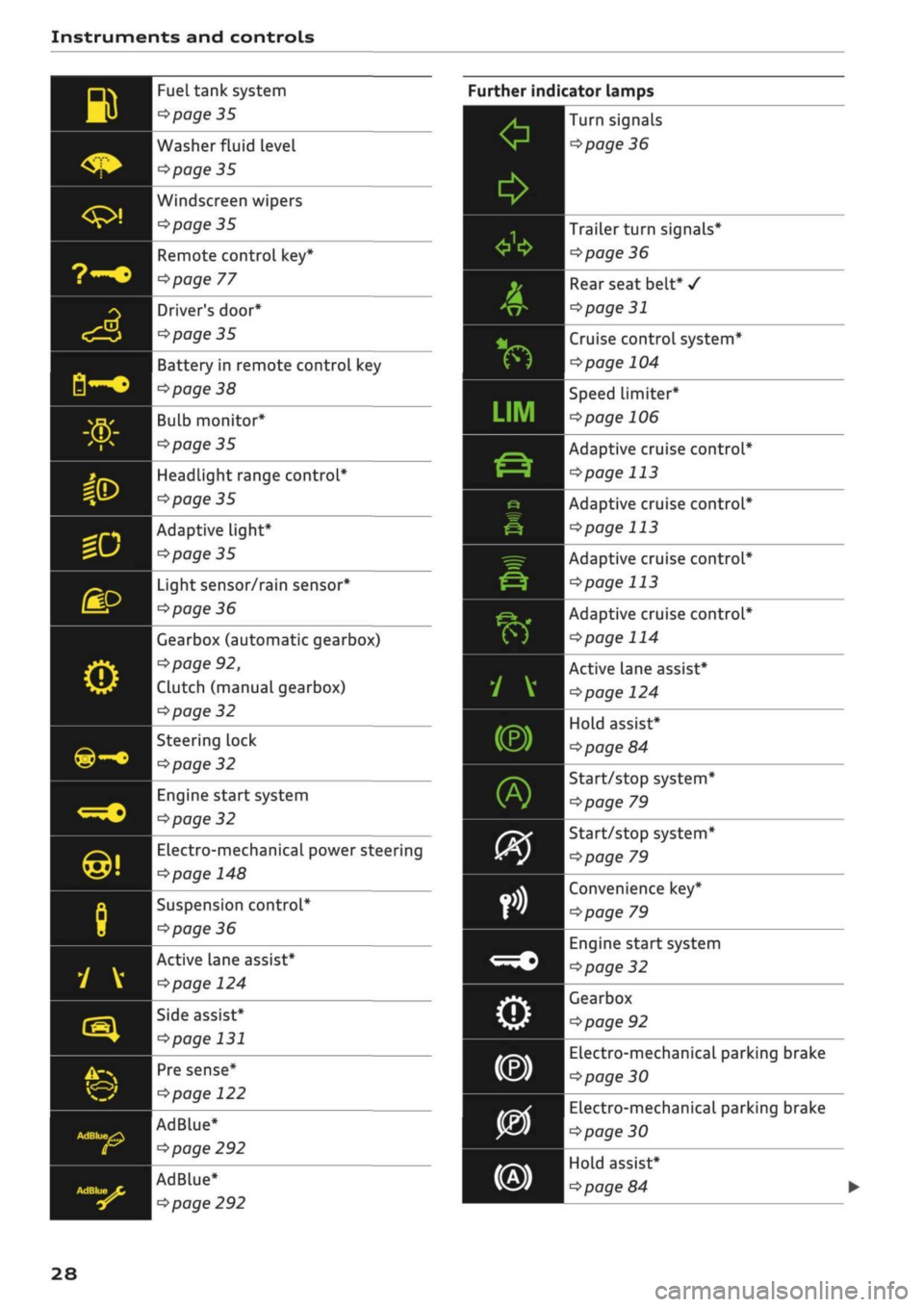
Further indicator lamps
0
*
A
&
v*
f)
•
inn
LIM
jr~\.
Ë-?
e
ê
^=r
&
É?k*
f)
1 V
(®)
fi£
)
09
orit
fn
<=^c
o
Turn signals
^>page
36
Trailer turn signals*
^>page
36
Rear seat belt*
/
<3page
31
Cruise control system*
^>page
104
Speed Limiter*
ï>page
106
Adaptive cruise control*
^>page
113
Adaptive cruise control*
^>page
113
Adaptive cruise control*
^>page
113
Adaptive cruise control*
^>page
114
Active lane assist*
^>page
124
Hold assist*
^>page
84
Start/stop system*
<^page
79
Start/stop system*
^•page
79
Convenience key*
^page
79
Engine start system
<=>page
32
Gearbox
ï>page
92
Electro-mechanical parking brake
^>page
30
Electro-mechanical parking brake
^>page
30
Hold assist*
^>page
84
Page 34 of 364
Instruments and controls
When the vehicle has gathered speed you will al
so hear
a
warning chime.
Applies to: vehicles with manual gearbox
© Note
For further information on the seat belts
•=>
page 275.
©-•
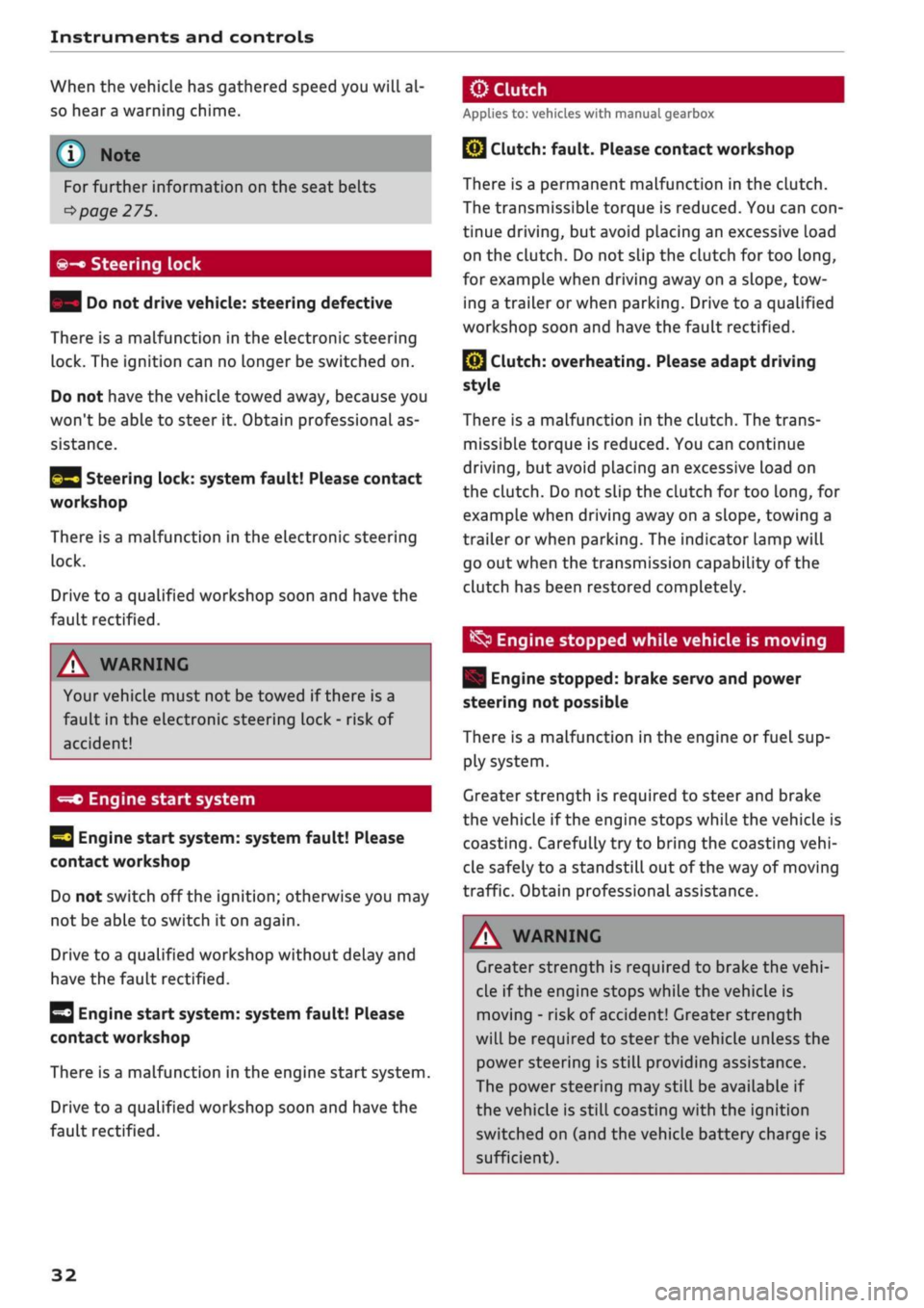
Steering lock
| Do not drive vehicle: steering defective
There is a malfunction in the electronic steering
lock. The ignition can no longer be switched on.
Do not have the vehicle towed away, because you
won't be able to steer it. Obtain professional as
sistance.
^3
Steering lock: system fault! Please contact
workshop
There is a malfunction in the electronic steering
lock.
Drive to a qualified workshop soon and have the
fault rectified.
A WARNING
Your vehicle must not be towed if there is a
fault in the electronic steering Lock - risk of
accident!
-=*>
Engine start system
H
Engine start
system:
system fault! Please
contact workshop
Do not switch off the ignition; otherwise you may
not be able to switch it on again.
Drive to a qualified workshop without delay and
have the fault rectified.
3
Engine start
system:
system fault! Please
contact workshop
There is a malfunction in the engine start system.
Drive to a qualified workshop soon and have the
fault rectified.
jBy
Clutch:
fault. Please contact workshop
There is a permanent malfunction in the clutch.
The transmissible torque is reduced. You can
con
tinue driving, but avoid placing an excessive load
on the clutch. Do not slip the clutch for too
long,
for example when driving away on a slope, tow
ing a trailer or when parking. Drive to a qualified
workshop soon and have the fault rectified.
Q}
Clutch: overheating. Please adapt driving
style
There is a malfunction in the clutch. The trans
missible torque is reduced. You can continue
driving,
but avoid placing an excessive load on
the clutch. Do not slip the clutch for too
long,
for
example when driving away on a slope, towing a
trailer or when parking. The indicator lamp will
go out when the transmission capability of the
clutch has been restored completely.
^
Engine stopped while vehicle is moving
| Engine stopped: brake servo and power
steering not possible
There is a malfunction in the engine or fuel sup
ply system.
Greater strength is required to steer and brake
the vehicle if the engine stops while the vehicle is
coasting.
Carefully try to bring the coasting
vehi
cle safely to a standstill out of the way of moving
traffic. Obtain professional assistance.
A WARNING
Greater strength is required to brake the
vehi
cle if the engine stops while the vehicle is
moving - risk of accident! Greater strength
will be required to steer the vehicle unless the
power steering is still providing assistance.
The power steering may still be available if
the vehicle is still coasting with the ignition
switched on (and the vehicle battery charge is
sufficient).
32
Page 35 of 364
Instruments and controls
CO
< o rN
iv
rN
•-i
00
£=s
Bonnet
| Warning! Bonnet not locked. Stop vehicle
and check bonnet lock
If the warning lamp lights up and the message
appears, the bonnet lock is not correctly engag
ed.
Stop your vehicle without delay and close the
bonnet
^page
296.
f*lu
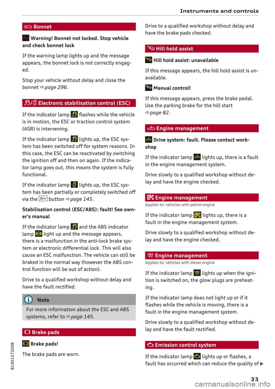
Electronic stabilisation control (ESC)
If the indicator lamp
§jj
flashes while the vehicle
is in motion, the ESC or traction control system
(ASR) is intervening.
If the indicator lamp
§|j
lights up, the ESC sys
tem has been switched off for system reasons. In
this case, the ESC can be reactivated by switching
the ignition off and then on again. If the indica
tor lamp goes out, this means the system is fully
functional.
If the indicator lamp
|g
lights up, the ESC sys
tem has been partially or completely switched off
via the
J^OFF
button
^>page
145.
Stabilisation control (ESC/ABS): fault! See
own
er's manual
If the indicator lamp
§§J
and the ABS indicator
lamp
EJ
light up and the message appears,
there is a malfunction in the anti-lock brake sys
tem or electronic differential lock. This will also
cause an ESC malfunction. The vehicle can still be
braked in the normal way (however the ABS
con
trol function will be out of action).
Drive to a qualified workshop without delay and
have the fault rectified.
(T)
Note
For more information about the ESC and ABS
systems, refer to
^>page
145.
O Brake
pads
S
Brake pads!
The brake pads are worn.
Drive to a qualified workshop without delay and
have the brake pads checked.
*S
Hill hold assist
|§i
Hill hold assist: unavailable
If this message appears, the hill hold assist is un
available.
Manual control!
If this message appears, press the brake pedal.
Use the parking brake for the hill start
^>page
82.
<^b
Engine management
Drive system: fault. Please contact work
shop
If the indicator lamp
Qg
lights up, there is a fault
in the engine management system.
Drive slowly to a qualified workshop without de
lay and have the engine checked.
EPC Engine management
Applies to: vehicles with petrol engine
If the indicator lamp
\$fi
lights up, there is a
fault in the engine management system.
Drive slowly to a qualified workshop without de
lay and have the engine checked.
W
Engine management
Applies to: vehicles with diesel engine
If the
indicator
Lamp
|jjj
Lights up when the
igni
tion is switched on, the glow plugs are preheat
ing.
If the indicator lamp does not light up or if it
flashes while the vehicle is moving, there is a
fault in the engine management system.
Drive slowly to a qualified workshop without de
lay and have the fault rectified.
O
Emission control system
If the indicator Lamp
£3 Lights
up or flashes, a
fault has occurred which can reduce the quality of •
33
Page 42 of 364
Doors and windows
Unlocking the vehicle
•
Take hold of the driver's/front passenger's door
handle. The
door
will be unlocked automatical-
iy-
•
To open the door, pull the door handle.
Locking the vehicle
• Automatic gearbox: Move the selector lever to
position P; otherwise it will not be possible to
lock the vehicle.
•
To lock the vehicle, close the door and touch
the sensor on the door handle once
^>Fig.
24,
•=>
A.-
Do
not
take hold of the door handle
while doing so.
The vehicle can be locked/unlocked from the
front doors only. The remote control key should
be within a range of about 1.5 metres from the
door handle. It does not matter where you carry
the key, for instance whether it is in your jacket
pocket or in a handbag or briefcase.
The Locking function may be affected if
you
grasp
the door handle while the vehicle is being locked.
Once the doors have been locked, they cannot be
opened again immediately. This will enable you
to check that the driver's door is properly closed.
The system will unlock either all the doors or only
one of the doors, depending on the settings you
have chosen on the infotainment system
•=>
page 41.
A\
WARNING
- Read and follow all the warnings
<=>
A
in
De
scription on page 37.
- Applies to vehicles with anti-theft alarm
system:
Do not leave anyone (especially
chil
dren) in the car if it is locked from the out
side and the safelock mechanism* is activa
ted:
the doors and windows cannot then be
opened from the inside
opage
42. Locked
doors could delay assistance in an emergen
cy, potentially putting lives at risk.
® Note
•
To save electrical power, the proximity
sen
sors are switched off after
a
few days. You
will then need to pull the door handle once
to unlock the vehicle, and a second time to
open it.
•
To prevent the vehicle battery from becom
ing discharged and thus maintain the
vehi
cle's starting ability for as long as possible,
the power management system will gradu
ally switch off convenience functions that
are not required. In this case you may not
be able to unlock the vehicle with this
con
venience function.
Central locking switch
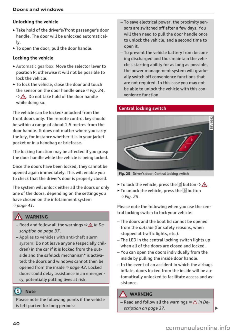
Fig.
25 Driver's door: Central locking switch
•
To lock the vehicle, press the [a] button
o A-
•
To unlock the vehicle, press the
M
button
=>
Fig.
25.
Please note the following when you use the
cen
tral locking switch to lock your vehicle:
- The doors and the boot lid cannot be opened
from the outside (for safety reasons, when
stopped at traffic lights, etc.).
- The LED in the central locking switch Lights up
when all of the doors are closed and locked.
- You can open the doors individually from the
inside by pulling the inside door handLe.
- In the event of an accident in which the airbags
inflate,
doors Locked from the inside will be au
tomatically unlocked to facilitate access and as
sistance.
Please note the following points if the vehicle
is left parked for long periods:
A WARNING
- Read and follow all the warnings
•=>
A in De
scription on page 37.
40
Page 46 of 364
Doors and windows
Power-operated boot lid
Applies to: vehicles with power-operated boot lid
The
boot lid can be opened and closed automati
cally.
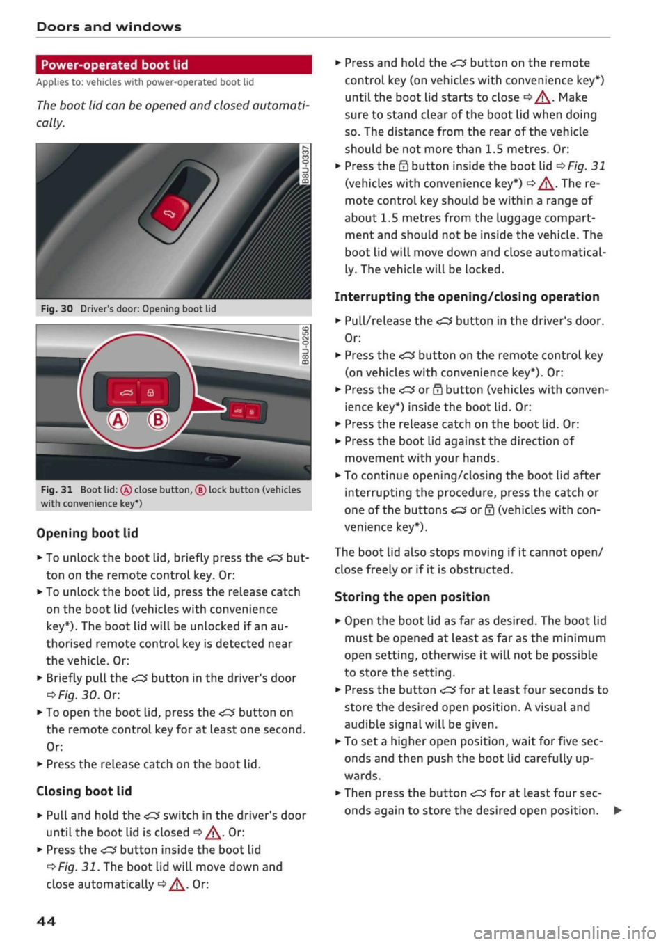
Fig.
30 Driver's door: Opening boot lid
Fig.
31 Boot lid:
(Â)
close button, ® lock button (vehicles
with convenience key*)
Opening boot lid
•
To unlock the boot lid, briefly press the
ton on the remote control key. Or:
•
To unlock the boot lid, press the release catch
on the boot Lid (vehicles with convenience
key*).
The boot lid will be unlocked if an au
thorised remote control key is detected near
the vehicle. Or:
•
Briefly
pulL
the
<£3
button in the driver's door
oFig.
30.
Or.
*•
To open the boot lid, press the
<^>'
button on
the remote control key for at least one second.
Or:
•
Press the release catch on the boot lid.
Closing boot lid
• Pull and hold the
<£3
switch in the driver's door
until the boot lid is closed
o/^.
Or:
•
Press the
«
button inside the boot lid
^>Fig.
31. The boot lid will move down and
close automatically
^^.
Or:
•
Press and hold the
<£3
button on the remote
control key (on vehicles with convenience key*)
until the boot lid starts to close
c>^.
Make
sure to stand clear of the boot lid when doing
so.
The distance from the rear of the vehicle
should be not more than 1.5 metres. Or:
•
Press the
0
button inside the boot lid
^>Fig.
31
(vehicles with convenience key*)
|=>^.
The re
mote control key should be within a range of
about 1.5 metres from the luggage compart
ment and should not be inside the vehicle. The
boot lid will move down and close automatical
ly. The vehicle will be locked.
Interrupting the opening/closing operation
•
Pull/release the
<£3
button in the driver's door.
Or:
•
Press the
^
button on the remote control key
(on vehicles with convenience key*). Or:
•
Press the
<£3
or
0
button (vehicles with conven
ience key*) inside the boot lid. Or:
•
Press the release catch on the boot lid. Or:
•
Press the boot lid against the direction of
movement with your hands.
•
To continue opening/closing the boot lid after
interrupting the procedure, press the catch or
one of the buttons
<£2
or 0 (vehicles with
con
venience key*).
The boot lid also stops moving if it cannot open/
close freely or if it is obstructed.
Storing the open position
•
Open the boot lid as far as desired. The boot Lid
must be opened at least as far as the minimum
open setting, otherwise it will not be possible
to store the setting.
•
Press the button
<£3
for at least four seconds to
store the desired open position. A visual and
audible signaLwill be given.
• To set
a
higher open position, wait for five sec
onds and then push the boot lid carefully up
wards.
•
Then press the button
«£3
for at least four sec
onds again to store the desired open position.
44