change time AUDI Q3 2015 Owners Manual
[x] Cancel search | Manufacturer: AUDI, Model Year: 2015, Model line: Q3, Model: AUDI Q3 2015Pages: 258, PDF Size: 64.9 MB
Page 4 of 258
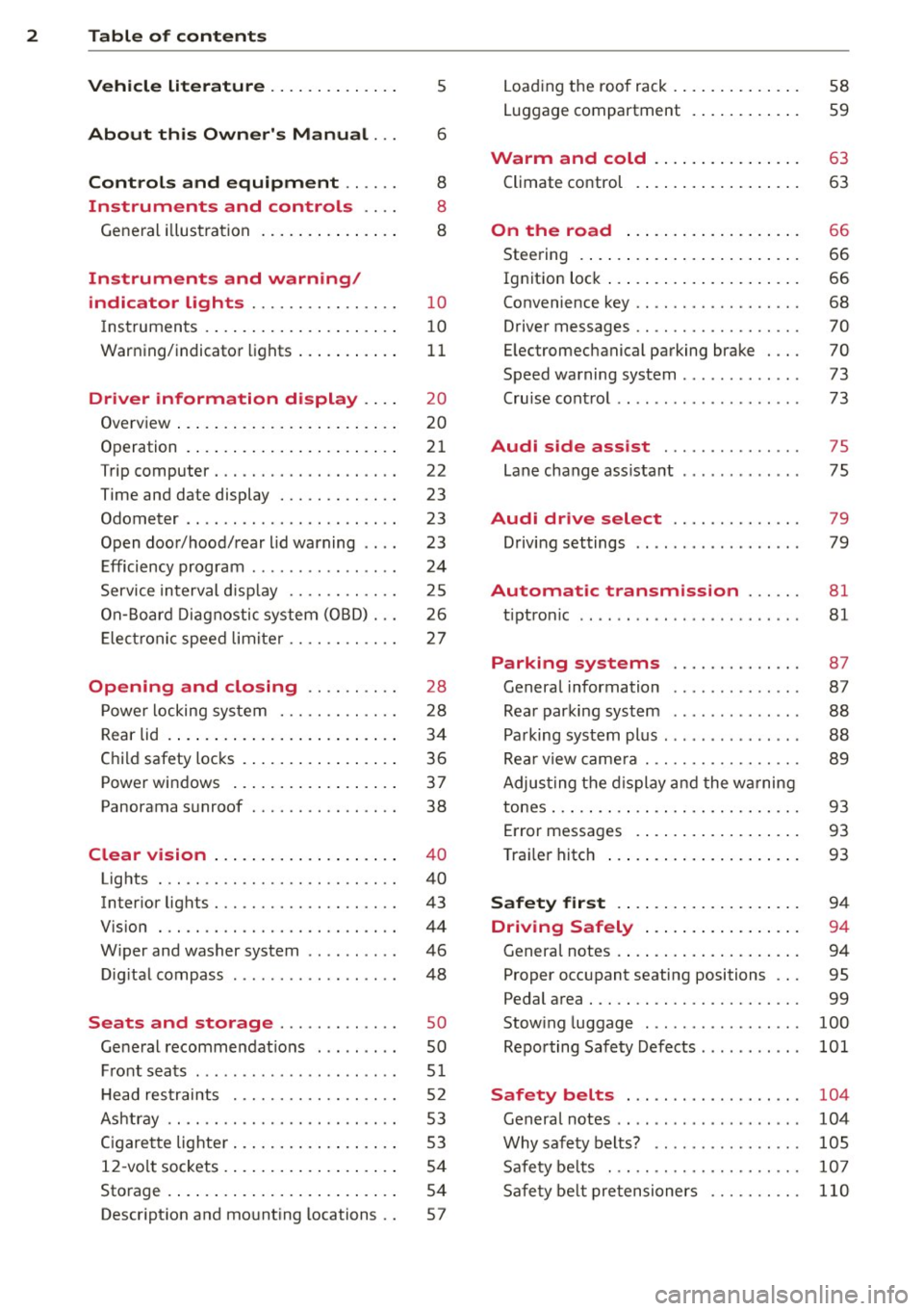
2 Table of contents Vehicle literature .. .. .. .. .. ... .
5
About this Owner's Manual . . . 6
Controls and equipment .. ... .
Ins truments and controls .. . .
General illus tration .... ... .. .. ... .
Instruments and warning /
indicator lights ........ .. .. .. . .
Ins truments . .. .. ..... ... .. .. ... .
War ning/ indi cator lights ... .. ... .. .
Driver information d isplay .. . .
Overview ... ... .. ..... ... .. .. ... .
Operation . .... .. ..... ... .. .. ... .
Trip computer . ........... .... ... .
Time and date display ..... .. .. .. . .
Odometer .. ........ ..... .. ..... .
Open doo r/hood/ rear lid warning .. . .
E fficiency p rogram ......... ... .. . .
S ervice in terval d isp lay .... .. .. ... .
On -Board D ia gnostic system ( OBD) . . . 8
8
8
1 0
1 0
11
2 0
20
2 1
22
23
23
23
24
2 5
26
Ele ctr onic spee d lim iter . . . . . . . . . . . . 2 7
Opening and closing .. .. .. .. . .
Powe r locking sy stem ..... .. .. .. . .
Rear lid ..... .. .. ..... ... .. .. ... .
C hil d safety locks . ..... ... .. .. ... .
Power win dows .. ..... ... .. .. ... .
Panorama s unroof ........ .. .. ... .
Clear vision .. .. ..... ... .. .. ... .
Lights . .. .. .. . .......... .. .. ... .
Inter ior lights ............. ... ... .
V 1s 1on . ...... ........... .... ... .
W iper and washer system . ... .. .. . .
Di gita l compass ........... ... .. . .
Seats and storage ...... ..... . .
Ge neral recomme ndat ions ..... .. . .
F ront sea ts .... .... ...... .. .. .. . .
H ead re straints .......... .. .. .. . .
Ashtr ay .. .. ............. ....... .
C igare tte lig hte r . ...... ... .. .. ... .
1 2- vo lt sockets . .. ..... ... .. .. ... .
Sto rage ..... .. .. ..... ... .. .. ... . 28
2
8
3 4
3 6
37
38
4 0
40
43
44
46
4 8
so
so
51
5 2
53
53
5 4
54
Descr ipt ion and mo unt ing locations . . 57 L
oad ing the roof rack . .. ..... .... . .
Luggage compartment . ..... ... .. .
Warm and cold .. ... ..... ... .. .
Climate control . .... .. ..... .... . .
On the road ... .. ... ..... ... .. .
Stee ring . ..... .. .. .... .... ... .. .
Ig nit ion lock ..... ... .. ..... .... . .
Convenience key .. ... .......... .. .
D river messages .. ............... .
E lectromechanical parking brake . .. .
Speed warning system . .......... . .
Cru ise cont ro l .. .. ............... .
Audi side assist .............. .
Lane change ass istant . .......... . .
Audi dr ive select ... ... ..... .. .
Driving set tings .. ..... ......... . .
Automatic transmission ... .. .
tiptron ic .. .. .. .. .. ... .. ... ..... .
Parking systems
58
59
63
63
66
66
66
68
70
70
73
73
75
75
79
79
81
81
87
Genera l information . . . . . . . . . . . . . . 87
Rea r parking syste m . . . . . . . . . . . . . . 88
P a rking system plus . . . . . . . . . . . . . . . 88
Rea r view came ra . . . . . . . . . . . . . . . . . 89
Adjus ting the display and the w arning
tones ... .. .... .. .. ... ..... ... .. . 93
E rror messages . . . . . . . . . . . . . . . . . . 93
T ra ile r hitch . . . . . . . . . . . . . . . . . . . . . 93
Safety fir st . . . . . . . . . . . . . . . . . . . . 94
Driving Safely . . . . . . . . . . . . . . . . . 94
Genera l notes . . . . . . . . . . . . . . . . . . . . 94
Proper occ upant seating positions . . . 95
Pedal area . . . . . . . . . . . . . . . . . . . . . . . 99
Stow ing luggage . . . . . . . . . . . . . . . . . 100
Reporting Sa fety Defects . . . . . . . . . . . 101
Safety belts . . . . . . . . . . . . . . . . . . . 104
General notes . . . . . . . . . . . . . . . . . . . . 104
Why safety belts? . . . . . . . . . . . . . . . . 105
Safe ty be lts . . . . . . . . . . . . . . . . . . . . . 107
Sa fe ty be lt pretensioners . . . . . . . . . . 110
Page 20 of 258
18 Instruments and warning/indicator lights
't':r.,. Engine oil sensor
1!11a Oil level sensor: System fault!
If the symbol illuminates, contact your au
thor ized Audi dealer a nd have the oil sensor
inspected. Until you have th is done, check the
oil level each time you refuel just to be on the
safe side~
page 184.
Bil Tank system
DD Please refuel
If the indicator light turns on for the first
time and the message appears, there are
about 1.8- 2.2 gallons (7.0 -8.5 li ters) of fue l
l eft in the tank . Time to refuel
~page 176.
ID'J Fuel tank system malfunction! Contact
dealer.
If the indicator light turns on and th is mes
sage appears, there is a malfunction in the
tank system.
Drive to your authorized Aud i dealer immedi
ately to have the malfunction corrected .
If the symbol illuminates, add windshield
washer fluid to the windshield washer system .
©-Engine start system
Ill Engine start system: Malfunction! Please
contact dealer.
If the indicator light turns on and the mes
sage appears, do
not sw itch the ignition off
because you may not be able to switch it on
again.
Drive to your authorized Aud i dealer immedi
ately to have the malfunction corrected .
Engine start system: Malfunction. Please
contact dealer.
There is a malfunction in the engine start sys
tem . Drive to
your authorized Audi dealer immedi
ately to have the ma lfunction corrected.
i§i Defective light bulb warning
If the J:I indicator light turns on, a bulb has
failed. The message ind icates the location of
the bu lb .
Vehicle lights: System fault!
If the message appears, there is a malfunc
tion in the headlights or lig ht switch.
Drive to your authorized Audi dealer immedi
ately to have the malfunction corrected .
&, WARNING
-Light bulbs are pressurized and could ex
p lode whi le they are being changed caus
ing serio us personal injury.
- Work with due care when handling the
high-vo ltage section of gas discharge
(xenon) lights*. Failure to do so could re
sult in death or serious injury.
{D Tips
Have the bulb replaced or the connect ion
r epaired by your authorized Audi Service
department.
~0 Headlight range control
II Headlight range control: System fault!
If the symbol II illuminates , the dynamic
headlight range control is no longer working
proper ly . Have the system checked and re
paired at your a uthorized Audi dea ler.
§0 Audi Adaptive Light
Appl ies to vehicles : wit h Audi adapt ive light
mfl Audi adaptive light: System fault!
If the indicator light turns on and this mes
sage appears, there is a malfunction in the
adaptive light system. The headlights still
funct ion.
Page 25 of 258
M N M N
0 ;::::, co
rl I.O
"' rl
"' rl
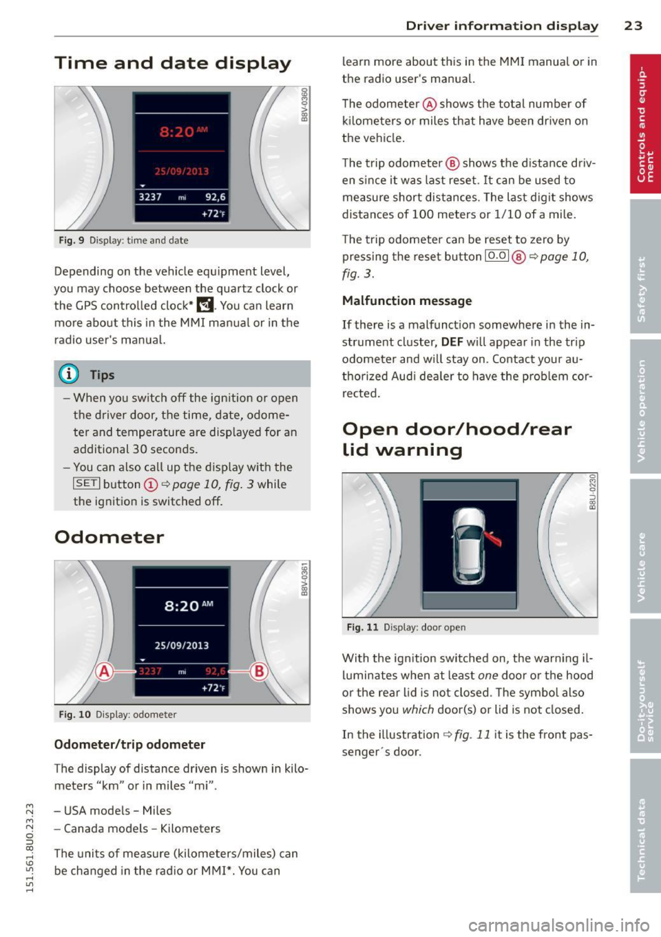
Time and date display
Fig. 9 Dis pl ay: time an d date
Depending on the veh icle equ ipment leve l,
you may choose between the quartz clock or
the GPS control led clock*
l!j . You can learn
more about this in the MMI manual or in the
radio user's ma nua l.
(D Tips
- When you switch off the ign ition or open
the driver door, the time, date, odome
ter and temperature are disp layed for an
additional 30 seconds.
- You can also call up the display w ith the
I SET I b utton (D ~ page 10, fig . 3 while
the ignition is switched off.
Odometer
F ig. 10 Dis play : odomete r
Odometer /trip odometer
The display of distance driven is shown in kilo
meters "km" or in miles "mi" .
- USA mode ls - Miles
- Canada models -Kilometers
The uni ts of me asure (kilometers/miles) can
be changed in the rad io or MMI*. You can
Dri ver inform ation di spl ay 23
learn more about this in the MM I manual o r in
the radio use r's manual.
T he odometer @shows the total number of
k il ometers o r miles that have been dr iven on
the vehicle.
The trip odometer @ shows the d istance driv
en since it was last reset . It can be used to
measure short distances. The last d igit shows
distances of 100 meters or 1/10 of a mi le.
The trip odometer can be reset to zero by pressing the reset button I
0.0 I @ ~ page 10,
fig. 3.
Malfunction message
If there is a malfunct ion somewhere in the in
strument cluster,
DEF w ill appear in the trip
odometer and w ill stay on . Contact your au
thorized Aud i dea le r to have the prob lem cor
r ected .
Open door/hood/rear
lid warning
F ig. 1 1 Dis play : door o pen
0
"' N 9 ::::, 0:, a,
With the ign ition sw itched on, the warn ing il
luminates when at least
one door o r the hood
or the rear l id is not closed . T he symbo l also
shows you
which door(s) or lid is not closed.
In the illustration
~ fig . 11 it is the front pas
senger · s door.
Page 27 of 258
M N M N
0 ::i co
rl I.O
"' rl
"' rl
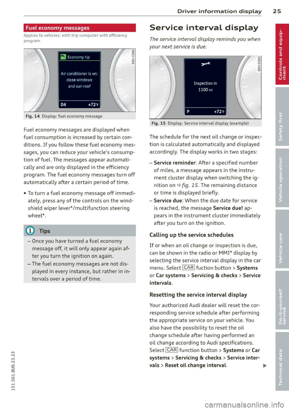
Fuel economy messages
App lies to vehicles: with trip computer w it h eff ic iency
p rogram
Fig . 14 Display: fuel economy message
Fue l economy messages are disp layed when
fuel consumption is increased by certain con
ditions. If you follow these fuel economy mes
sages, you can reduce your vehicle's consump
tion of fuel. The messages appear automati
cally and are only displayed in the effic iency
program. The fuel economy messages turn off
automatically after a certain period of time.
• To turn a fuel economy message off immedi
ately, press any of the controls on the wind
shield wiper lever*/multifunction steering
whee l* .
(D} Tips
- Once you have turned a fuel economy
message off, it will only appear again af
ter you t urn the ignition on aga in.
- The fuel economy messages are not dis
played in every instance, but rather in in
te rva ls over a period of time.
Dri ver inform ation di spl ay 25
Service interval display
The service interval display reminds you when
your next service is due.
Fig. 15 Display: Service interval display (example)
The schedule for the next o il change or inspec
t ion is ca lculated automatica lly and disp layed
accord ingly. The d isp lay works in two stages:
-Serv ice rem inder: After a spec ified number
of miles, a message appears in the instru
ment cluster display when switching the ig
nition on
¢fig. 15. The rema ining dis tance
or time is displayed br iefly.
- Se rvi ce due : When the due date for serv ice
is reached, the message
Se rvic e due! ap
pears in the instrument cluster immediate ly
after you turn on the ignition .
Calling up the service schedules
If or when an oil change or inspection is due,
can be shown in the rad io or MMI* disp lay by
selecting the service i nte rva l display in the car
menu . Selec t!CAR ! fuction button>
Sy ste m s
or C ar s ystem s > Ser vicing & check s > Service
intervals.
Resetting the service interval displa y
Your author ized Audi dealer will reset the cor
respondi ng service schedule after pe rforming
the appropr iate service on your veh icle. You
also have the possibi lity to reset the oil
change schedule after having performed an
oil change according to Audi specifications.
Se lect !CARI function button>
Sy stem s or Ca r
sy ste ms
> Servicing & checks > Service int er-
val s
> Reset oil cha nge int erval. ""
Page 28 of 258
26 Drive r in form ation d ispl ay
(D Note
-Only reset the oi l change display when
you have completed an o il change .
- If you d isconnect the battery term inals,
no calculatio ns can be made for the serv
ice interval display during this time and
no service rem inder will appear . Remem
ber that observing the proper service in
tervals is vitally important to extending
the life of you r vehicle, particularly the
engine, and maintaining its value. Even if
the mileage dr iven is low, the max imum
period of one year from one serv ice to
the next must not be exceeded.
On-Board Diagnostic
system (OBD)
Malfunction Indicator Lamp (MIL)
The Malfunction Ind icator Lamp (MIL) ¢'4 i n
the instrument cluster is part of the On-Board
Diagnostic (OBD II) system.
The warning/indicator light illuminates when
the ign ition is switched on and goes o ut after
the engine starts and the idle has stabilized.
Th is indicates that the MIL is working proper
l y.
If the light doe s not go out after the eng ine
is started, or illuminates wh ile you are driv
ing, a ma lfunction may exist in the engine sys
tem . If the light illuminates, the catalytic con
verter cou ld be damaged.
Continue driving
w ith reduced pow er (avoid
ing sustained high speeds and/or rapid accel
erations) and have the condition corrected.
Contact your authorized Audi dealer .
If the light ill uminates, the electronic speed
limiter may also be ma lfunctioning . For more
information
¢ page 2 7, Electronic speed
limiter.
An imp roperly clo sed fuel filler c ap m ay als o
c a u se th e M IL l ight to illuminate
¢ page 177.
On-Board Diagnostics
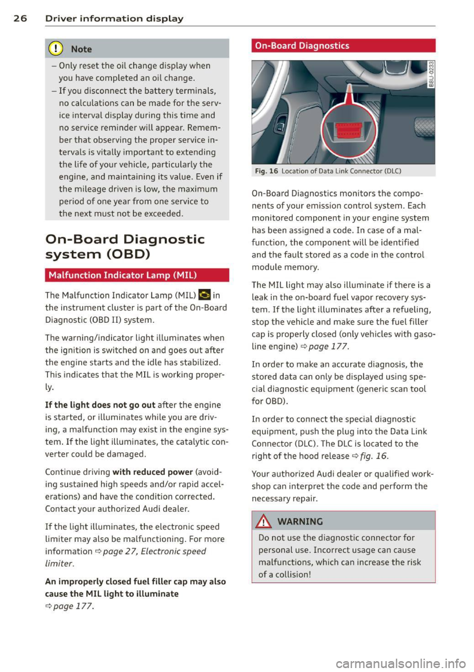
Fig. 16 Locat io n of Data Li nk Conn ector (DLC)
On-Board D iagnostics monitors the compo
nents of your em ission contro l system . Each
monitored component in your engine system
has been ass igned a code . In case of a mal
funct ion, the component will be identified
and the fault stored as a code in the control
module memo ry.
The MIL light may also illuminate if there is a lea k in the on-board fuel vapor recove ry sys
tem . If the ligh t illuminates after a refueling,
stop the vehicle and make sure the fuel fille r
cap is prope rly closed (only vehicles w ith gaso
line engine) ¢
page 177.
In order to make a n accurate diagnosis, the
stored data can on ly be displayed using spe
c ial d iagnostic equipment (generic scan tool
for OBD).
In order to con nect t he special diagnostic
equipment, push the plug in to the Data Link
Connector (D LC). The D LC is located to the
right o f the hood release
<::!;> fig. 16.
Your a uthorized Audi dea le r or qua lified wor k
shop can interpret the code and perform the
necessary repair.
,&_ WARNING ~ -
Do not use t he diagnost ic connecto r fo r
personal use . Incorrect usage can cause
mal functions, wh ich can increase the risk
of a collision!
Page 32 of 258
30 Opening and clo sing
@ Tips
- The operation of the remote contro l key
can be temporarily disrupted by interfer
ence from transmitters in the vicinity of
the veh icle work ing in the same frequen
cy range (e.g. a cell phone, radio equip
ment) .
- For security reasons, replacement keys
are on ly available from author ized Audi
dealer .
- For Decla ration of Compliance to United
States FCC a nd Industry Canada regula
t ions
9 page 24 0.
Check light and battery in remote
master key
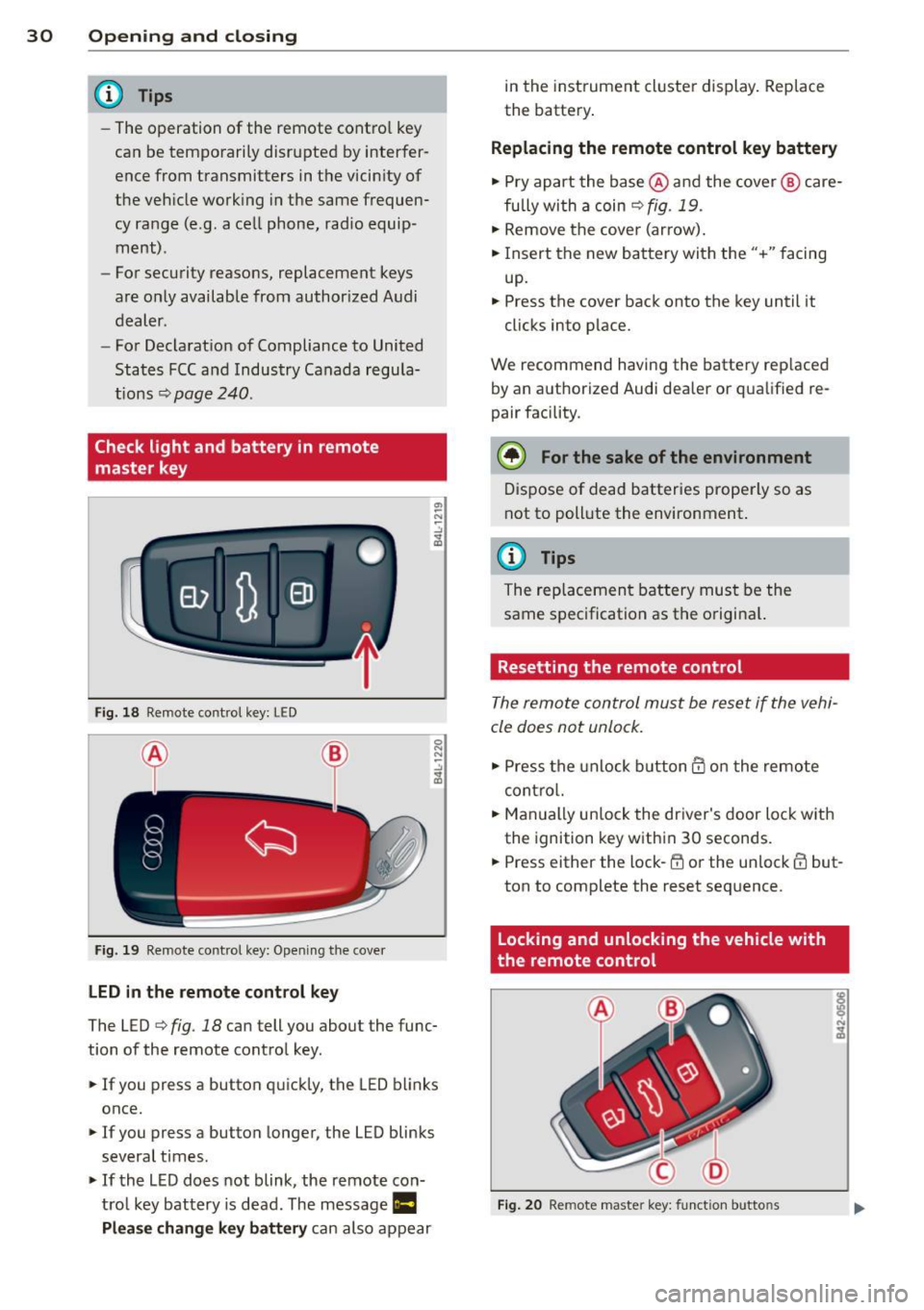
Fig . 18 Remote co nt rol key : LE D
Fi g. 19 Remote co ntrol key: Open in g the cove r
LED in the remote cont rol key
The LED 9 fig . 18 can tell you about the func
tion of the remote contro l key .
.. If you press a button q uickl y, the LED blinks
once.
1> If you press a button longer, the LED blinks
several times .
.. If the L ED does not blink, the remote con
tro l key battery is dead. The message
Ill
Plea se change key battery can also appear in
the instrument cluster display . Rep lace
the batte ry .
Replacing the remote control key battery
.. Pry apart the base @and the cover @ care
fu lly with a coin~
fig. 19.
.,. Remove the cove r (ar row) .
.. Insert the new battery with the" +" facing
up.
.. Press the cove r back onto the key until it
clicks into p lace.
We recommend having the battery rep laced
by an a uthorized Audi dea ler or qua lified re
pair facility .
$ For the sake of the environment
Dispose of dead batteries prope rly so as
not to poll ute the environment.
(D Tips
The rep lacemen t battery mus t be the
same spec ification as the origina l.
Resetting the remote control
The remote control must be reset if the vehi
cle does not unlock .
.. Press the unlock b utton @on the re mote
contro l.
.. Man ually un lock the dr iver's door loc k with
the ignition key w ith in 30 seconds .
.. Press either the lock-~ or the unlock @ but
ton to complete the reset seq uence.
Locking and unlocking the vehicle with
the remote control
Fig . 20 Remote maste r key: funct ion butto ns
Page 42 of 258
40 Clear vision
Clear vision
Lights
Switching the lights on and off
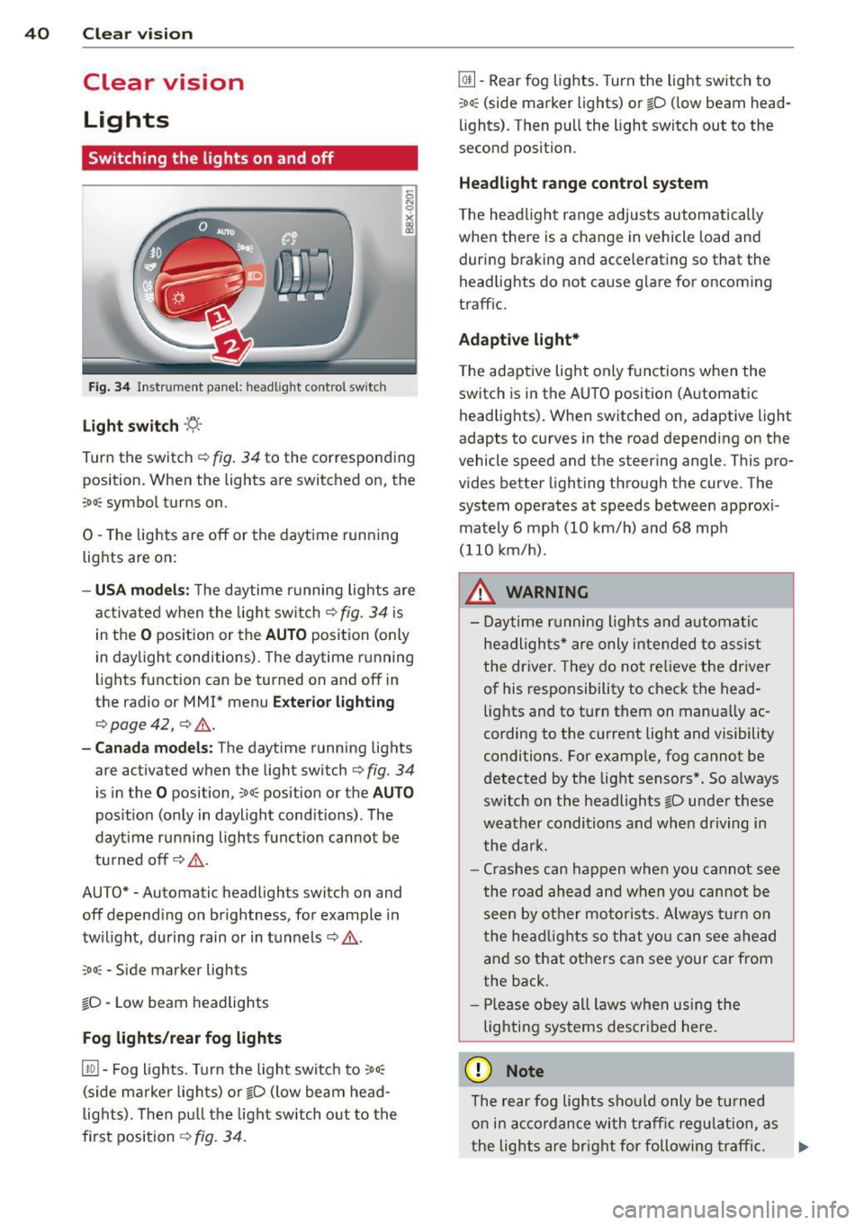
Fig . 34 Instrument panel: headlight control switch
Light switch -'t;. -
Tu rn the switch ¢ fig. 34 to the corresponding
position. When the lights are switched on, the
:oo : symbol turns on.
0 -The lights are off or the daytime running
lights are on:
- USA models: The daytime running lights are
activated when the light switch¢
fig. 34 is
in the
O position or the AUTO position (only
in daylight conditions). The daytime running
lights function can be turned on and off in
the radio or
MMI* menu Exterior lighting
¢ page 42, ¢ ,& .
-Canada models : The daytime running lights
are activated when the light switch¢
fig. 34
is in the O posi tion, co o: position or the AUTO
position (only in daylight conditions). The
dayt ime running lights function cannot be
turned off¢,& .
AUTO* -Automatic headligh ts swi tch on and
off depending on brightness, for example in
twilight, during rain or in tunnels¢,& .
:oo: -Side marker lights
io -Low beam headlights
Fog lights /rear fog lights
[!Q] -Fog lights. Turn the light switch to :oo:
(side marker lights) or io (low beam head
lights). Then pull the light switch out to the
first position ¢
fig. 34.
@I] -Rear fog lights. Turn the light switch to
:oo : (side marker lights) or io (low beam head
lights). Then pull the light switch out to the
second position .
Headlight range control system
The headlight range adjusts automatically
when there is a change in veh icle load and
during braking and accelerating so that the
headlights do not cause glare for oncoming
traffic.
Adaptive light*
The adaptive light only functions when the
switch is in the AUTO position (Automatic
headlights). When switched on, adapt ive light
adapts to curves in the road depending on the
vehicle speed and the steering angle. This pro
vides better lighting through the curve . The
system operates at speeds between approxi
mately 6 mph (10 km/h) and 68 mph
(110 km/h) .
_&. WARNING
- Daytime running lights and automatic
headlights* are only intended to assist
the driver. They do not relieve the driver
of his responsibility to check the head
lights and to turn them on manually ac
cording to the current light and visibility
conditions. For example, fog cannot be
detected by the light sensors*. So always
sw itch on the headlights
io under these
weather conditions and when driving in
the dark.
- Crashes can happen when you cannot see
the road ahead and when you cannot be
seen by other motorists. Always turn on
the headlights so that you can see ahead
and so that others can see your car from
the back.
- Please obey all laws when using the
lighting systems described here.
(D Note
The rear fog lights should only be turned
on in accordance with traffic regulation, as
-
the lights are bright for following traffic. .,._
Page 45 of 258
M N M N
0 ::i co
rl I.O
"' rl
"' rl
light switch is in the AUTO position
¢ page 40, fig. 34.
Daytime running lights
USA models : You can switch the dayt ime run
ni ng lights
on an d off .
Canada models:
The function cannot be
turned off .
It is ac tiva ted automat ica lly each
time the ignition is switc hed o n.
Emergency flashers
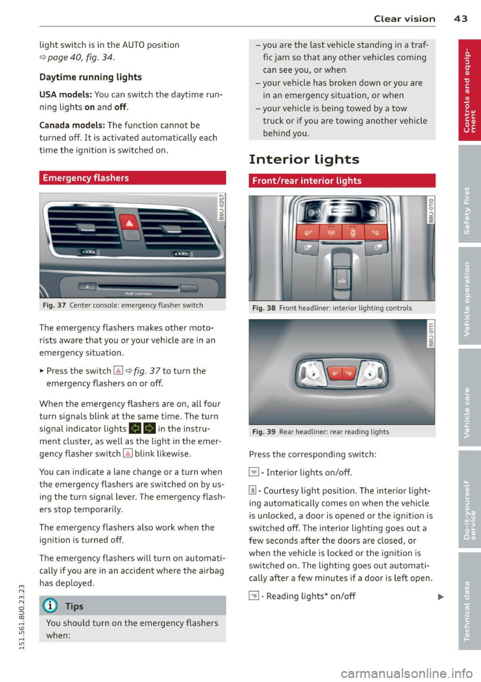
Fig . 3 7 Cente r conso le : emerge ncy flashe r sw itch
The emergency flashers makes other moto
rists aware that you or your vehicle are in an
emergency situation .
.,. Press the sw itch
Gil ¢ fig. 3 7 to turn the
emergency flashers on or off.
When the emergency flashers are on, all four turn signals blink at the same time. The turn
signa l ind icator lig hts
II 18 in the instru
ment cluster, as well as the light in t he emer
gency flashe r switch
[Ai bli nk likewise .
You can indicate a lane change or a turn when
the emergency flashers are switched on by us
ing the tu rn signa l lever . The emergency flash
e rs stop temporar ily.
The emergency f lashers also work when the
ignit io n is turned off.
The emergency flashers will turn o n automati
cally if you are in an accident where the airbag
h as dep loyed.
@ Tips
You shou ld t urn on t he emergency flashers
when:
Clear vi sion 43
- yo u are the la st veh icle standing in a t ra f
fic jam so that any other ve hicles coming
can see you, o r whe n
- yo ur vehicle has bro ken dow n or you are
in an emergency s ituation, o r when
- yo ur vehicle is be ing towed by a tow
truck or if you are towing another vehicle
beh ind you.
Interior Lights
Front/rear interior lights
Fig . 38 Fro nt headl iner: int eri or lig h ting co ntro ls
Fi g. 39 Rear headli ner: rea r read ing lig hts
Press the corresponding switch:
~ -In ter ior lig hts on/off .
[ii-Courtesy light pos it io n. The inter ior lig ht
ing auto mati ca lly comes o n when t he ve hicl e
i s un lo cke d, a door i s ope ned or the ig nitio n is
switched off. The interior lighting goes o ut a
few seconds after the doors a re closed, or
whe n the vehicle is locked or the ignition is
switched on. The lighting goes out automati
ca lly after a few minutes if a door is left open .
~ -Read ing lights * on/o ff ..,.
Page 60 of 258
58 Seat s a nd s tor ag e
attached to it to fall off the roof onto the
road .
- Objects falling from the roof of a vehicle
can cause a crash and persona l injury.
- Only mount the roof rack on the desig
nated locations on the roof¢
fig. 64 .
- The roof rack system must be insta lled
exactly according to the instructions pro
vided.
- When driving with a roof rack system,
changes to the center of gravity and wind
resistance can change the vehicle han
dling and lead to a collision . Always
adapt your driv ing and your speed to the
current conditions .
(D Note
-Your vehicle warranty does not cover any
damages to the veh icle caused by using
roof racks or mount ing structures not
approved by Audi for your vehicle . The
same applies to damage resulting from
i nco rrect roof rack installation .
-Always check the roof rack mountings
and hardware before each trip and dur
i ng a tr ip to make sure eve rythi ng is se
cu rely tightened. If ne cessary, retighten
the mo unt ings and check the ent ire sys
tem from time to time.
- After mounting a roof rac k system, or
when you transport objects on the roof
of your vehicle, the height of the vehicle
is natura lly increased . Be careful when
driving under low br idges or in parking
garages for examp le. This could cause
damage to the load and even the vehicle
i tself .
- Make sure that the open rear lid and the
sunroof do not come into contact w ith
objects on the roof .
Loading the roof rack
Always distribute loads evenly. Make sure
any thing on the roof rack is securel y tied
down.
.. Always distrib ute the loads on the roof rack
even ly.
.. Always attac h it em s to the roof rack securely
before you dr ive off .
T he max im um perm issible roof weight is
165 lb (75 kg ). The roof we ight is the total of
the weigh t of the roof rack, the at tachments
and the cargo you are carrying . You must a lso
not exceed the maximum load we ight for the
r oof rack you are using.
When using a roo f rack system which has a
lower load carrying capacity , you must not use
up the tota l maximum permiss ible load carry
ing capac ity specified above. Instead, you
shou ld load the roof rack system only to the
maximum capacity specified by the manufac
tu rer of the roo f rack sys tem.
A WARNING
=
Weak, damaged or imprope r straps used
to secure items to the roof rack can fail
d uring hard braking or in a coll is ion and
cause ser ious personal injury.
- Make sure the roof rack is installed exact
ly as specif ied above ¢
page 5 7.
- Always use s uitable mounting straps for
secur ing items to the roof rack to help
prevent items from sh ifting or flying for
ward .
- Items on the roof rack must always be
securely mounted.
- The use of a roof rack can negatively af
fect the way a vehicle hand les . Cargo
that is large, heavy, bulky, long or flat
will have a greater negat ive influence on
the vehicle's aerodynamics, center of
g rav ity and overall handling. Always
d rive s lowly, avoid s udden bra king and
maneuvers when transporting ca rgo on
the roof of your vehicle .
~
Page 67 of 258
M N
M N
0 ::i co ,...., \!) 1.1'1 ,...., 1.1'1 ,....,
0 Adjusting the temperature
Separate temperatures can be selected for the
driver's and front passenger's side using the
left and right rotary controls . The tempera
ture can be adjusted between +60
°F (+16 °C)
and +84 °F (+28 °C) . Outside this range, LO or
HI will appear on the air conditioner display .
In the two extreme settings the air condition
er operates continuously with maximum cool
ing or heating output, and the temperature is
not regulated automatically.
[:]1 (±] Adjusting the airflow
You can adjust the volume of air delivery man
ually to suit your individual requirements.
Press the
IAUTOI button for automatic blower
regulat ion .
~/1 :J!/l~ I Adjusting the air distribution
You can direct the flow of air manually to se
lected outlets. The buttons can be operated
e ither separately or in combination . Press the
IAUTOI button for automat ic air distribution.
J Adjusting the seat heating
When you press the button, the seat heating
is switched on at level 3 (the highest level) .
The LEDs indicate the temperature level. To
reduce the temperature, press the button
again . T o switch off the seat heating, press
the button repeatedly unti l all the LEDs have
gone out.
The seat heating automatically switches from level 3 to level 2 after 10 minutes .
I@ F RON T! Switching the defroster on/off
The windscreen and s ide windows are defrost
ed or demisted as quickly as possible . The air
output is increased to maximum and most of
the air comes out of the outlets below the
windscreen . The air recirculation mode is de
activated. The temperature should be set to
+ 72
°F (22 °() or higher.
The defroster is switched off when the
I AUTO I
button is pressed .
Warm and cold 65
!iii! REAR ! Switching the rear window
heating on/off
The rear window heating operates only when
the engine is running and switches off auto
matically after about 10 minutes.
Synchronisat ion
By pressing and ho lding the IAU TO j button,
you can set the temperature of the front pas
senger's side to the temperature of the driv
er's side. The synchronisation is deactivated as
soon as the temperature on the front pas
senger's s ide is changed .
Air outlets
The thumbwhee ls can be used to open and
close the air outlets in the center and on ei
ther side of the dashboard and rear center
console . The lever in the center of the outlets
can be used to adjust the direction of air flow.
Changing the temperature units
The temperature display can be switched be
tween
° F and 0C. Press and hold the 1- ·1 but
ton ¢
fig. 72 and turn the rotary control on
the driver's s ide to+ for 3 seconds.
A WARNING
- Do not use the recirculation for extended
periods of time. The windows could fog
up since no fresh air can enter the vehi
cle. If the windows fog up, press the air
recir culation button again immediately
to switch off the air recirculation func
tion or se lect defrost .
- Individ uals w ith reduced sensitivity to
pain or temperature could develop burns
when using the seat heating function. To
red uce the risk of injury, these individu
als should not use seat heating .
(D Note
To avoid damage to the heating elements
in the seats, do not kneel on the seats or
place heavy loads on a small area of the
seat.