instrument cluster AUDI Q3 2018 Owners Manual
[x] Cancel search | Manufacturer: AUDI, Model Year: 2018, Model line: Q3, Model: AUDI Q3 2018Pages: 230, PDF Size: 57.03 MB
Page 9 of 230
0 co ......
"' ,....
"' ...... 0 0 :::,
00
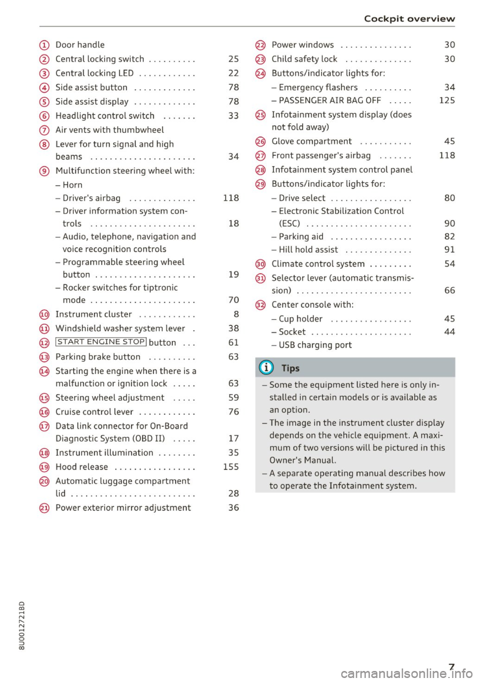
(!) Door handle
@
®
©
®
®
(J)
®
Central locking switch
Cent ral locking L ED ......... .. .
Side assist button
Side assist d isplay
H eadlight cont rol sw itch .... .. .
A ir vents with thumbwheel
L ever for turn s ignal and h igh
beams .. .. .... . .......... .. .
® Multifunction ste ering wheel with :
- Horn
- Driver's airbag ........... .. .
- Driver information system con-
trols .. .. ............... .. .
- Audio , te lephone, nav igation and
vo ice recognit ion controls
- Programmable steering wheel
button . .. .. ........... .. .. .
- Rocker switches for tiptronic
mode . ... .. ... ..... ... .. .. .
@ Instrument cluster ........... .
@ Windshield washer system lever
@ I S TART EN GIN E ST OPI button .. .
@ Pa rking brake button ....... .. .
~ Starting the engine when there is a
malfunction or ignition lock . ... .
@ Steer ing whee l adjustment .... .
@ Cruise contro l lever .... ... .. .. .
@ Data link connector for On-Board
Diagnostic System (OBD II) .. .. .
@ Inst rument illum ination ... .. .. .
@ Hood r ele as e .... ..... ... .. .. .
@ Automat ic luggage compartment
lid .. .. ... ............. ..... .
25
2 2
78
78
33
34
118
18
19
70
8
38
61
63
63
59
76
17
35
155
28
@ Power exterior mirror adjustment 3 6
Cockpit o ve rv iew
@ Power windows . .. .. .. ..... .. .
@ Child safety lock ............. .
@ Buttons/indi cator lights for:
- Eme rgency flashers .. ..... .. .
- PASSENG ER AIR BAG O FF .... .
@ Infotainment system display (does
not fold away)
@ G love compartment .......... .
@ Front passenger's airbag ...... .
@ Infota inment system control panel
@ Buttons/indicator lights for:
- Drive se lect .. .. ............ .
- E lectronic Stabilization Control
( E SC) . .. .. .. .. ....... ..... .
30
30
34
125
45
118
80
90
- Park ing aid . . . . . . . . . . . . . . . . . 82
- Hill hold ass ist . . . . . . . . . . . . . . 91
@ Climate contro l system . . . . . . . . . 54
@ Se lector lever (automatic transm is -
sion) . . . . . . . . . . . . . . . . . . . . . . . . 66
@ Center conso le w ith:
- Cup holder . . . . . . . . . . . . . . . . . 45
- Socket . . . . . . . . . . . . . . . . . . . . . 44
- USB charging port
(D Tips
-Some the eq uipment listed here is on ly in
sta lled in certain models or is available as
an opt ion.
- The image in the instrument cluster d isplay
depends on the vehicle equipment. A maxi
mum of two versions will be pictured in th is
Owner's Manual.
- A separate operat ing manua l describes how
to operate the Infota inment system .
7
Page 10 of 230
Instrumen ts and ind icator ligh ts
Instruments and indicator Lights
Instruments
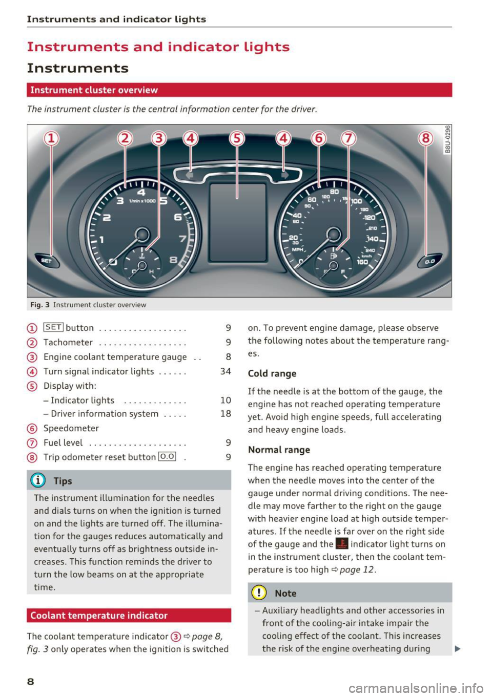
Instrument cluster overview
The instrument cluster is the central information center for the driver.
Fig. 3 Instrument cluster overv iew
(D ISETI button .... ........... .. .
Tachometer .... .. .. ..... .... .
Engine coolant temperature gauge 9
9
8 @
®
©
®
Turn signal ind icator lights ..... . 34
Disp lay w ith:
- Indicator lights
- Driver information system
10
18
@ Speedometer
0
®
Fu el level .. .... ........... .. .
Trip odometer reset button 10.0 1
@ Tips
The instrument illumination for the needles
and dia ls turns on when the ignition is turned
on and the lights are turned off. The illumina
tion for the gauges reduces automat ica lly and
eventually turns off as brightness outside in
creases . T his function reminds the drive r to
turn the low beams on at the approp riate
time.
Coolant temperature indicator
9
9
The coolan t temperature indic ato r@ r=:> page 8,
fig. 3 only operates when the igni tion is switched
8
"'
"' N
0
;::) a,
"'
on. To prevent engine damage, please observe
the following notes about the temperature rang
es.
Cold ran ge
If the needle is at the bottom of the gauge, the
engine has not reached operating temperature
yet. Avoid high eng ine speeds, full accelerating
and heavy engine loads.
Normal range
The engine has reached operating temperature
when the needle moves into the center of the
gauge under norma l driving condit ions. The nee
dle may move farther to the right on the gauge
with heavier engine load at hig h outside temper
atu res . If the needle is far ove r on the r ight side
of the gauge and the. in dicator light turns on
i n the instrument cluster, then the coolant tem
peratu re is too high
r=;, page 12.
(D Note
- Aux ilia ry headlights and ot her accessories in
front of the coo ling-a ir intake impa ir the
cooling effect of the coolant. This increa ses
the risk of the engine overheating dur ing ..,_
Page 11 of 230

a
co
...... N r--. N .-< 0 0 ::, co
high outside temperatures and heavy en
gine load .
- The front spoiler also he lps to distribute
cooling air correctly while driving. If the
spoiler is damaged, the cooling effect will
be impaired and the risk of the engine over
heating will increase. See an authorized
Audi dealer or authorized Audi Service Fa
cility for assistance.
Tachometer
The tachometer displays the engine speed in rev
olutions per minute (RPM) .
You should shift to the next lowest gear when
the engine speed is below 1,SOO RPM . The begin
ning of the red zone in the tachometer indicates
the maximum permissible engine speed for all
gears once the engine has been broken in and
when it is warmed up to operating temperat ure.
Before reaching the red zone, you shou ld shift in
to the next higher gear, choose the Dor S selec
tor lever position, or remove your foot from the
accelerator pedal.
CD Note
The needle in the tachometer @Q page 8,
fig. 3 may only be in the red area of the gauge
for a short time or there is a risk of engine
damage.
@ For the sake of the environment
Upshifting ea rly helps you to save fuel and re
duces operating noise.
Fuel level
The fuel level indicator only operates when the
ignition is switched on.
The
tD ¢ page 15 turns on if the reserve quan
tity of fue l is reached.
The fuel tank capacity of your vehicle is listed in
the
Technical Data section ¢ page 210.
CD Note
Never drive until the tank is completely emp
ty. The irregular supply of fuel that results
Instruments and indicator lights
from that can cause engine misfires . Uncom
busted fuel will then enter the exhaust sys
tem. This can cause overheat ing and damage
to the catalytic converter.
Odometer
Fig. 4 I n st ru me nt cluster : odometer
Trip odometer and odometer
The trip odometer @ shows the distance driven
since it was last reset. It can be used to measure
short distances.
T he trip odometer can be reset to zero by press
ing the
10.01 reset button @~ page 8, fig. 3.
The odometer @shows the total distance that
the vehicle has been driven.
Malfunction indicator
If there is a malfunction in the instrument clus
ter,
DEF will appear in the trip odometer display.
Have the malfunction corrected as soon as possi
ble.
Time/date display
You can switch between the quartz clock or the
GPS controlled clock* depending on the vehicle
equipment. For more information, refer to your
MMI Operating Manual.
Outside temperature display
The instrument cluster display shows the outside
temperature. At temperatures below 42 °F ( +S
°C), a snowflake symbol appears in front of the
temperature display . .,.
9
Page 12 of 230
Instruments and indicator lights
If your vehicle is stationary or if you are driving at
very low speeds, the temperature displayed may
be slightly higher than the actua l temperature
outside due to the heat radiating from the en
g ine.
A WARNING
Do not assume the roads are free of ice based
on the outs ide temperat ure display . Be aware
that there may be ice on roads even when the
outside temperature is around 42 °F (+5 °C)
a nd that ice can increase the risk of accidents .
You can set the un its used for temperat ure,
speed and other measurements in the Info
tainment system.
Indicator lights
Description
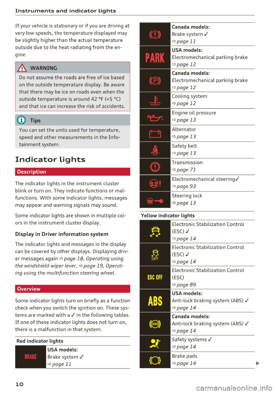
The indicator lights in the instrument cluster
blink or turn on . They indicate funct ions or ma l
functions . With some indicator lights , messages
may appear and war ning signals may sound .
Some indicator lights are shown in multiple col
ors in the instrument cluster display.
Di splay in Driver informat ion sy st e m
The indicato r lights and messages in the disp lay
can be covered by other displays. Disp laying driv
er messages again¢ page 18, Operating using
the windshield wiper lever,¢ page 19, Operat
ing using the multifunction steering wheel.
Overview
Some ind icator lights turn o n briefly as a function
check when you switch the ign ition on. These sys
tems are mar ked wit h a./ in the following tables .
I f one of these indica to r li gh ts does not turn on,
the re is a ma lfunction in that system.
Red indicator lights
10
--------------
US A mod els:
Brake system ./
¢ page 11
Canada model s:
Brake system ./
¢page 11
USA model s:
E lectromechanical parking brake
¢ page 12
Canada model s:
Elec trome chanical parking b rake
¢ page 12
Cooling system
¢ page 12
Engine oil pressure
¢ page 13
Alternator ¢ page 13
Safety be lt
¢ page 13
T ransmission
¢ page 71
El ectrome chanical stee ring ./
¢ pag e 93
Stee ring lock
¢page 13
Yello w ind icator lights
--------------
El ectron ic Stabil ization Co ntro l
( E SC) ./
¢page 14
E lectron ic Stabilization Control
(ESC) ./
¢ page 14
E lectron ic Stabilization Contro l
(ESC)
¢ page 89
USA models:
Anti-lock braking system (ABS) ./
¢ page 14
Canada model s:
Anti- lock b raking system (ABS) ./
¢ page 14
Safety systems ./
¢ page 14
Brake pads
¢ page 14
Page 19 of 230

a
co
...... N r--. N .-< 0 0 ::, co
/fj/c::::::::;/ c::5 Door, hood or luggage
compartment lid is open
II-If the indicator light turns on, then one of
the doors is not closed .
f-j-If the ind icator light tu rns on , then the hood
is not closed.
§-j -If the ind icator light turns on, then the lug
gage compartment lid is not closed.
On-Board Diagnostic
System (OBD)
Malfunction indicator lamp (MIL)
The malfunction indicator lamp (MIL) ¢.j in the
instrument cluster is part of the On-Board Diag
nostic System (OBD II).
The warning/indicator light turns on when the ig nition is switched on and turns off once the en
gine is started and is running in idle at a stab le
speed. This indicates that the MIL is functioning
correct ly.
If the light does not turn off after starting the
engine
or turns on while driving, this may indi
cate there is a malfunction in the engine.
If the
indicator turns on, the catalytic converte r may be
damaged .
Drive
with reduced engine performance (avoid
high speeds for extended periods of time and/or
fast acceleration) and have the malfunction cor
rected. See an authorized Aud i dealer or autho r
ized Audi Service Facility.
The MIL may also turn on if the fuel filler cap i s
not cl osed correctly
¢ page 153.
Instruments and indicator lights
On-Board Diagnostics
Fig. 5 Location o f Data Li nk Con necto r (OLC)
On-Board Diagnostics monitors the components
of your emission control system. Each monitored
component in your engine system has been as
s igned a code. In case of a malfunction , the com
ponent will be identified and the fault sto red as a
code in the control module memory.
The MIL light may also illuminate if there is a
leak in the on-board fuel vapor recovery system.
If the light illuminates after a refueling, stop the
vehicle and make sure the fuel f iller cap is prop
erly closed (only vehicles with gasoline engine)
r::'.>page 153 .
In order to make an acc urat e diagnosis, the stor
ed data can only be displayed using special diag
nostic equipment (generic scan tool for 080).
In order to connect the special d iagnost ic equip
ment, push the p lug into the Data Lin k Connector
(DLC). The DLC is located to the right of the hood
release ¢
fig. 5.
Your authorized Aud i dea ler or qualified work
shop can interpret the code and perform the nec
essary repair.
_& WARNING ~
Do not use the diagnostic connector for per-
sona l use. Incorrect usage can cause malfunc
tions, which can increase the risk of a colli
sion!
17
Page 20 of 230
Driver information system
Driver information
system
Overview
A pp lies to: ve hicles w ith driver information system
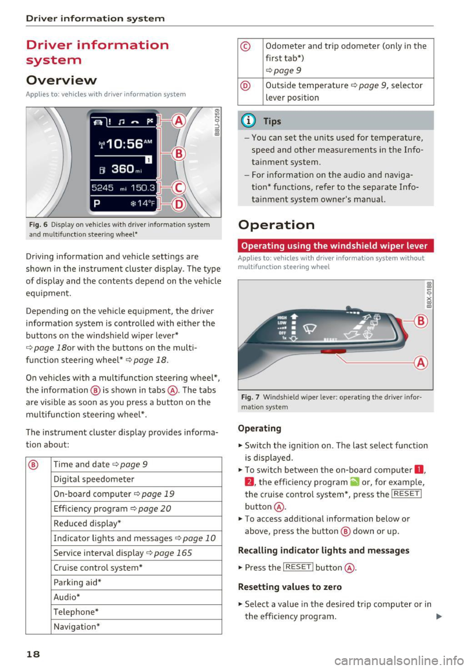
Fig. 6 Display on veh icles wit h driver informat ion system
and m ultifunc tion steering wheel*
:ll N 9 ::i a, ID
Driving information and vehicle settings are
shown in the instrument cluster display . T he type
of display and the contents depend on the vehicle
equipment.
Depending on the vehicle equ ipment, the driver
information system is controlled with either the
buttons on the windsh ield wiper lever*
¢ page 18or with the buttons on the mult i
function steering wheel*¢ page 18.
On vehicles with a multifunction steering wheel*,
the information ® is shown in tabs @. The tabs
are visible as soon as you press a button on the
multifunction steering wheel*.
The instrument cluster display provides informa
tion about:
® Time and date
¢ page 9
Dig ital speedometer
On -board computer¢ page 19
Efficiency program¢ page 20
Reduced display*
Indicator lights and messages¢ page 10
Serv ice interval display ¢page 165
Cruise control system* Parking aid*
Aud io*
Telephone* Navigation*
18
© Odometer and trip odometer (only in the
first tab*) ¢page
9
® Outside temperature~ page 9, selector
l ever posit ion
{!) Tips
- You can set the units used for temperature,
speed and other measurements in the Info
tainment system.
- For information on the audio and naviga
t ion* functions, refer to the separate Info
tainment system owner's manual.
Operation
Operating using the windshield wiper lever
Applies to : vehicles wit h dr iver infor mat ion system without
multif unct ion steer ing wheel
------ ®
Fig. 7 Windsh ie ld wipe r leve r: operating the drive r info r
ma tion system
Operating
~ Switch the ignit ion on . The last select function
is displayed.
~ To switch between the on -board computer 0 ,
fJ , the efficiency program a, or, for examp le,
the cruise contro l system*, press the
I RESET I
button@.
~ To access additiona l information below or
above, press the button ® down or up.
Recalling indicator lights and messages
~ Press the I RESET I button @.
Resetting values to zero
~ Select a value in the desired trip computer or in
the efficiency program. ..,.
Page 22 of 230
Driver information system
You can identify which on-board computer is cur
rently being shown in the disp lay based on the
small
O or fJ .
The on-board compu ter 0 ~ fig . 9 is a short-term
memory .
It collects driving information from the
time the ignition is switched on until it is switch
ed off. If you continue driving w ith in two hours
after switching the ignition off, the new values
are included when calculating the current trip in
formation .
Unlike the short-term memory, the long-term
memory (on-board computer
fJ ) is not erased
automatically. You can select the time period for
evaluating trip informat ion yourself .
You can call up the following information consec
utively in on-board computer
O or fJ :
-Date
-Range
- Travel time
- Average consumpt ion
- Average speed
- Distance
- Current fuel consumption
Inf ormation on the efficiency program
¢page 20.
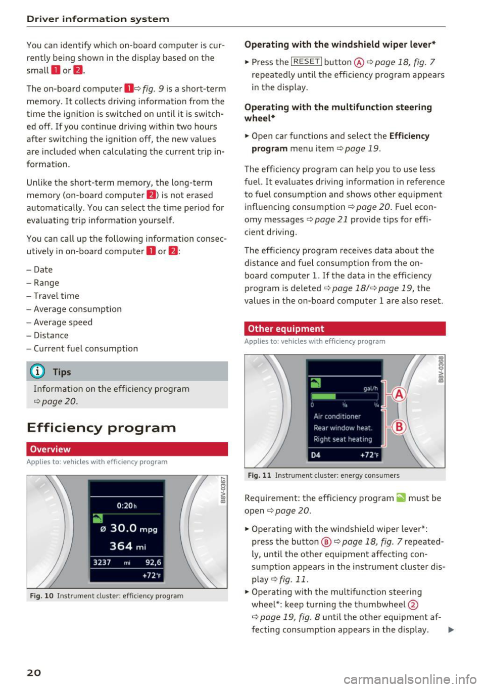
Efficiency program
Overview
App lies to: ve hicles w ith efficie ncy program
F ig. 10 Instrument cluster: efficiency program
20
Operating with the windshield wiper lever*
.,. Press the I RESET I button @¢ page 18, fig. 7
repeatedly until the efficiency program appears
in the display.
Operating with the multifunction steering
wheel*
.,. Open car functions and select the Efficiency
program
menu item ¢page 19.
The efficiency p rogram can help you to use less
fuel.
It evaluates dr iving information in reference
to fuel consumption and shows other equipment
influencing consumption
~ page 20. Fuel econ
omy messages ¢
page 21 provide tips for effi
c ient driving.
The effic iency program receives data about the
distance and fuel consumption from the on
board computer
1. If the data in the efficiency
program is deleted¢
page 18/¢ page 19, the
values in the on-board computer 1 are also reset.
Other equipment
App lies t o: vehicles wit h efficiency prog ra m
Fig. 11 Instrument cluster: energy cons umers
Requirement: the efficiency program ii must be
open ¢
page 20 .
.,. Operating with the windshield wipe r lever*:
press the button
@ ¢ page 18, fig. 7 repeated
ly, until the other equipment affecting con
sumption appears in the instrument cluster dis
play
~fig . 11 .
.,. Operating with the multifunction steering
wheel*: keep turning the thumbwheel @
~page 19, fig. 8 until the other equ ipment af-
fecting consumption appears in the display. .,..
Page 25 of 230
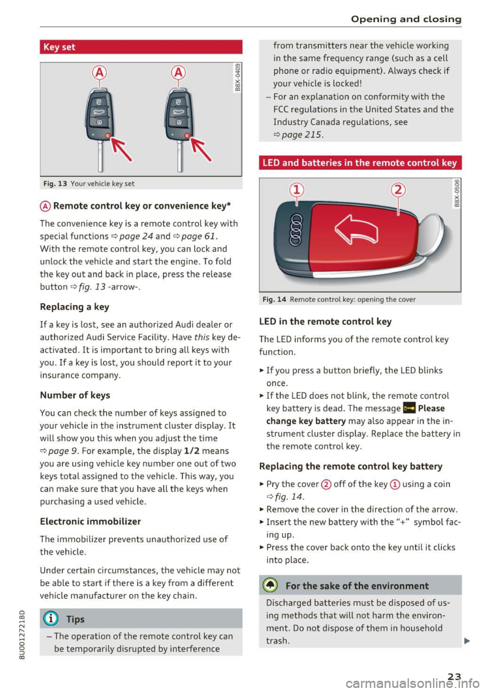
Key set
Fig. 13 Your vehicle key set
@ Remote control key or conven ience key*
The convenience key is a remote control key with
specia l functions ¢
page 24 and¢ page 61.
With the remote cont rol key, you can lock and
u nlock the vehicle and sta rt the eng ine . To fold
the key out and back in p lace, press the release
b utton ¢
fig. 13 -arrow- .
Replacing a key
If a key is lost, see an authorized Audi dealer or
author ized Audi Service Facility. Have
this key de
activated .
It is important to bring a ll keys with
you .
If a key is lost, yo u should report it to you r
in su rance company.
Number of keys
You can check the number of keys ass igned to
your veh icle in the instrument cluste r d isplay. It
will show you th is when you ad just the time
¢
page 9. For examp le, th e display 1/2 m eans
you are u sing veh icle key numbe r one ou t of two
keys tot al ass igned to th e vehicle. This w ay, yo u
can ma ke sure that you have all the keys whe n
pur chasing a used vehicle .
Electronic immobilizer
The immob ilizer prevents unautho riz e d use of
t he vehicle.
Unde r certain c ircumstances , the vehicle may not
be ab le to s tart if the re is a key from a different
ve hicl e manufact urer on the key cha in.
~ @ Tips N r--.
~ - The operation of the remote control key ca n
0 g be temporarily dis rupted by in terfe rence
(X)
Open ing and closing
fro m transmitters ne ar the veh icle wor king
in t he same fre quency range (such as a ce ll
phone or ra dio e quip ment) . Alwa ys c heck if
your vehicle is locked !
- For an ex pla nat io n on co nform ity w it h the
FCC regulat ions in t he Un ite d States and the
Indust ry Canada regulat ions,
see
¢page 215.
LED and batteries in the remote control key
Fig. 14 Re mote contro l key: ope ning the cover
LED in the remote control key
T he LED informs yo u of the remote co ntro l key
f unct ion .
... If you press a bu tton briefly, t he LED blinks
once.
... If the LED does not blin k, t he remote co ntro l
key batte ry is dead. The message
Ill Please
change key battery
may also appear in the in
strument cluster display . Replace the battery in
the remote cont rol key .
Replacing the remote control key battery
... Pry the cover@off of the key(!) usin g a coin
¢ fig. 14.
... Remove the cover in the d irection of the arrow.
... Inse rt the new batte ry with the" +" symbol fac
ing up .
... Press the cove r back onto the ke y unt il it clicks
into p lac e.
@ For the sake of the environment
Discha rg ed batter ies must be disposed o f us
i ng methods t hat w ill not harm t he env iron
m ent. Do no t disp ose of the m in hous ehold
t ra sh.
23
Page 36 of 230
Lights and Vision
-If you turn off the ignition whi le the exter ior
lights are on and open the door, a warning
tone sounds.
- In cool o r damp weather, the inside of the
headlights, turn s ignals and tail lights can
fog over due to the temperature d if f erence
between the inside and outside. They will
clear short ly after switch ing them on. This
does not affect the serv ice life of the light
i ng .
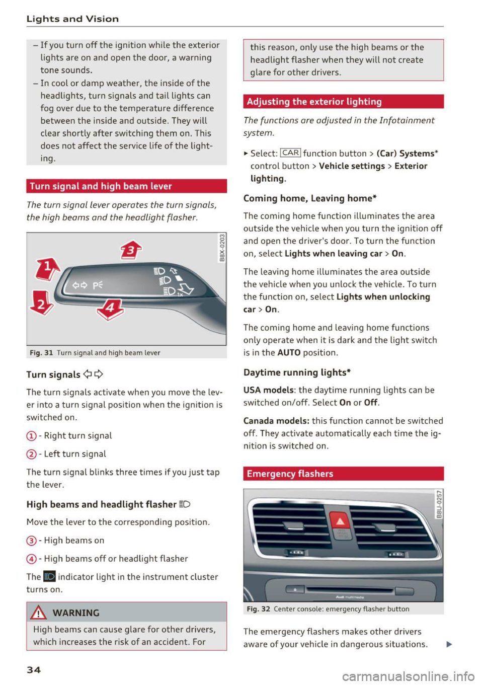
Turn signal and high beam lever
The turn signal lever operates the turn signals,
the high beams and the headlight flasher .
Fig. 31 Turn signal and high beam lever
Tu rn signals ¢ 9
The turn s ignals activate when you move the lev
er into a turn s ignal position w hen the ign ition is
sw itched on.
@ -Right turn signa l
@-Left turn signal
The turn signal blinks three times if you just tap
the lever.
High b eams and headl ight flasher ~D
Move the lever to the co rrespo nd ing pos it ion .
@ -High beams on
© -High beams off or headlig ht flasher
The
II indicator light in the instrument cluster
turns on .
A WARNING
High beams can cause glare fo r other drivers,
w hi ch increases the risk of an accident. For
34
this reason, only use the high beams or the
headlight flasher when they will not create
glare for other dr ivers.
Adjusting the exterior lighting
The functions are adjusted in the Infotainment
system .
.,.. Sele ct: !CAR ! function b utton> (Car ) Systems *
control button > Vehicle settings > Exte rior
lighti ng.
Coming home, Leaving home*
The coming home fun ction ill umin ates the a rea
outside the vehicle when you tu rn the ignit io n off
and open the driver's doo r. To turn the func tion
on, select
Light s when leaving car > On .
The leaving home illum ina tes the area ou tside
the ve hicle when yo u un lo ck the vehicle . To turn
the function on, se lect
Lights when unlocking
car > On.
The coming home and leav ing home func tions
on ly opera te when it is dar k and the l ight switc h
i s in the
AUTO position.
Daytime running lights*
USA models :
the daytime running lights can be
swit ched on/off. Sele ct
On or Off .
Canada models:
this function cannot be sw itched
off . They activate automatically each time the ig
nit ion is switched on .
Emergency flashers
Fig. 32 Center conso le: emerge ncy flasher button
The emergency flashers makes other drivers
aware of your veh icle in dange rous situations.
In N 0
~ Cl) m
Page 37 of 230
a
co
...... N r-N .... 0 0 ::, co
"' Press the &I. button to switch the emergency
flashers on or off.
You can indicate a lane change or a turn when the
emergency flashers are switched on by using the
turn signal lever . The eme rgency flashers stop
temporarily .
The emergency flashers also work when the igni
tion is turned off.
(D Tips
You shou ld sw itch the emergency flashers on
if:
- you are the last car in a t raff ic jam so that
all othe r vehicles approach ing from beh ind
ca n see you, or if
- you r vehicle has bro ken down or you are
having an emergency, or if
- you r vehicle is being towed or if you a re tow
i ng anot her vehicle
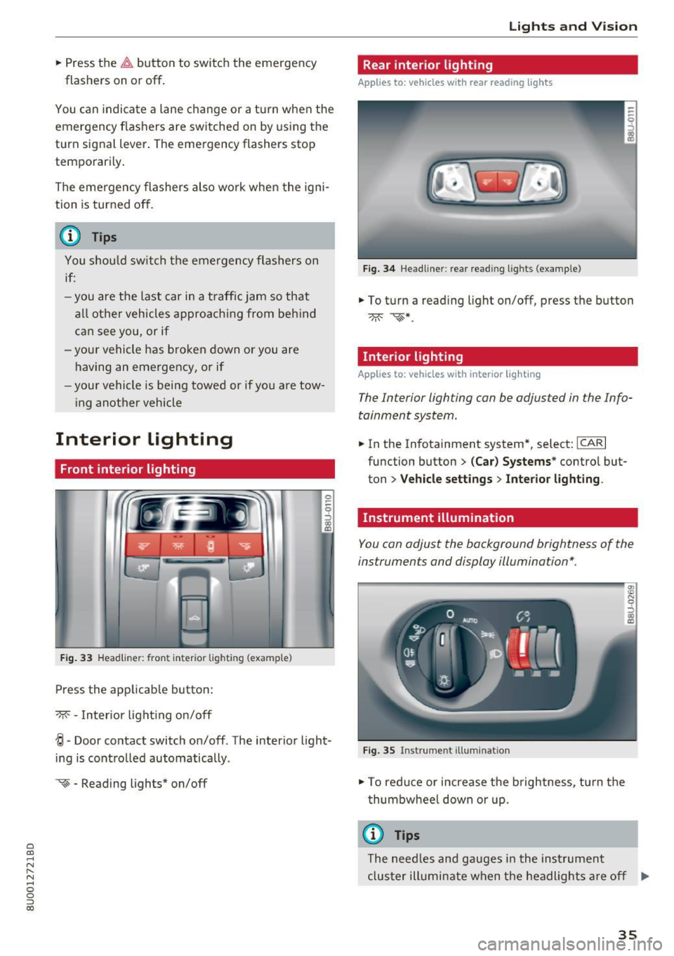
Interior Lighting
Front interior lighting
Fig . 33 Headliner: front inter ior lighting (example)
Press the app licab le button :
-M- -Inter ior light ing on/off
0
~
"' a,
~ - Door contact switch on/off . The interior light
ing is controlled automatically.
~ - Reading lights* on/off
Lights and V ision
Rear interior lighting
Applies to: vehicles with rear reading lights
Fig. 3 4 Headliner: rear reading l ights (example)
"' To turn a read ing light on/off, press the button
Interior lighting
Applies to: vehicles with interior lighting
The Interior lighting can be adjusted in the Info
tainment system.
"' In the Infotainment system*, select: ICARI
function button > (Car) Sy stems * control but
ton
> Vehicle setting s > Interior lighting .
Instrument illumination
You can adjust the background brightness of the
instruments and display illumination*.
F ig. 35 Instrument illuminat ion
"' To red uce or increase the b rightness, tu rn the
thumbwhee l down or up.
(D Tips
The need les and gauges i n the inst rument
cluster illumi nate when the headlights a re off
Iii>
35