engine AUDI Q3 2019 Owners Manual
[x] Cancel search | Manufacturer: AUDI, Model Year: 2019, Model line: Q3, Model: AUDI Q3 2019Pages: 280, PDF Size: 72.73 MB
Page 3 of 280
83A012721BA
Foreword
Thank you for choosing an Audi - we value your trust in us.
Your new Audi will allow you to experience the best in groundbreaking technology and premium quality
equipment that a vehicle has to offer. We recommend that you read your Owner's Manual thoroughly
so that you quickly become acquainted with your Audi and make use of all of its features.
In addition to explaining how the different features work, we provide many useful tips and information
concerning your safety, how to care for your vehicle, and how to maintain your vehicle's value. We also
give you useful tips and information on how to drive your vehicle more efficiently and in an environ-
mentally-friendly manner.
We hope you enjoy driving your Audi and we wish you safe and pleasant motoring.
AUDI AG
A WARNING
Operating, servicing and maintaining a passenger vehicle or
off-highway motor vehicle can expose you to chemicals includ-
ing engine exhaust, carbon monoxide, phthalates, and lead,
which are known to the State of California to cause cancer and
birth defects or other reproductive harm. To minimize expo-
sure, avoid breathing exhaust, do not idle the engine except as
necessary, service your vehicle in a well-ventilated area and
wear gloves or wash your hands frequently when servicing
your vehicle. For more information go to www.P65Warnings.
ca.gov/passenger-vehicle.
Page 5 of 280
83A012721BA
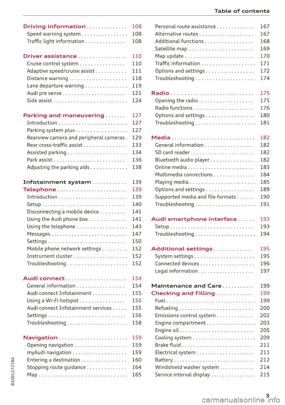
Table of contents
Driving information.............. 108
Speed warning system.........-..000- 108
Traffic light information.............. 108
Driver assistance................. 110
Cruise control systeM.......... 000 eee 110
Adaptive speed/cruise assist........... 111
Distance warning.................005 118
Lane departure warning............... 119
AUdi PrOSONsSe & seis + 2 mews 2» nee 2 oem 121
Side assist... 2... eee eee eee eee 124
Parking and maneuvering....... 127
IMtroduetion « x cicvers < e ersuens + x enavane oo saree 127
Parking system plus...............04. 127
Rearview camera and peripheral cameras. 129
Rear cross-traffic assist. ............-. 133
Assisted parking .............0.00005- 134
Parkassist': sexs « s neem sg aes + e wae 2 136
Adjusting the parking aids............. 138
Infotainment system............ 139
Telephone
Introduction
Setup..........
Disconnecting a mobile device......... 141
Using the Audi phone box............. 141
Using the telephone................0. 143
MESSAGES crus + ¢ ween ¢ 3 eeuen xy eee 4 2 ae 147
SOttiMGSicraice o saaneme « u eneneve © icameneies © eyeaeite 150
Mobile phone network settings......... 152
Instrument cluster.............2-.00. 152
Troubleshooting sais . eves 6 coarse es cae 152
AU CONMECE ces ¢ s xeee x 2 ews a i ee 154
Generalinformation................. 154
Audi connect Infotainment............ 155
Using a Wi-Fi hotspot................ 155
Audi connect Infotainment services..... 155
Settings............0 0.0000... 0000. 156
Troubleshooting sass ss eee ss ees ss ees 158
IIS VIG ABI. 5 cccccas os cones o enemies aoe 15S:
Opening navigation.................. 159
myAudi navigation.................0. 159
Entering adestination................ 160
Stopping route guidance.............. 164
Maize: = 2 sews ¢ 2 Som & eee Ee ees Fe eee 165
Personal route assistance............. 167
Alternative routes............02e000 167
Additional functions................. 168
Satellite mapiee e «sons e siemens ae aacens 2 4 ve 169
Map update............. 0. eee eee eee 170
Tratficintoritiationie: « : waa: xs seen 6 2 eu LZ)
Options and settings.............000e 172
Troubleshooting...............-.000- 174
R&GIO’: onic cs wea ss wens se eee & o Hews 175
Opening the radio................04. 175
Radio functions..................-4. 176
Options and settings...............0. 180
Troubleshooting.................0005 181
MG@Gias = acs ¢ = secs s © seme « s Seems so SeURS 182
General information ................. 182
SD card reader..........0.-..00 eee 182
Bluetooth audio player.............0. 182
Online Medias « ssi + exes ae omens oo veer 183
Multimedia connections.............. 184
Playing tedia. = s sees s 2 sees se wees ee 185
Options and settings...............0. 189
Supported media and file formats...... 190
Troubleshooting «ess 2s secu se vee ss ees 191
Audi smartphone interface...... 193
Setup... ee eee eee eee eee 193
Troubleshooting............ee eee eee 194
Additional settings.............. 195
SySteMm Settings: < saws ss sews se eee & 195
Connected devices............ 0 cee ee 196
Legal information................... 197
Maintenance and Care........... 199
Checking and Filling............. 199
FUGlaias s os08,8 & aay @ § aovon & § Sanne 8 OF eee 199
RePUCLING: is «a cms so ewes oe ese vB seen 200
Emissions control system............. 202
Engine compartment................. 203
EMGIMeiOils: acre « ¢ qaiea & © meee s 2 seNoN 8 Es 205
Cooling system. ............--00 00 eee 209
Brake fluid... . 0... eee eee eee 211
Electrical system.........--.0----05- 211
Battery. =o cecness « ommnaine « 0 omecwne 6 3 oats = oe 212
Windshield washer system............ 214
Service interval display............... 215
Page 9 of 280
83A012721BA
Quick access
Electromechanical parking brake
button ......... cece eee eee 90
Selector lever (automatic transmis-
SION) 26... eee ee eee eee 82
Audi phone Dox esessie so seas & 6 cere 141
START ENGINE STOP] button .... 80
Depending on equipment: ®®®
— Starting the engine when there is
amalfunction ............0005 81
—Ignition lock ................. 80
@3) Steering wheel adjustment ...... 56
@4 Lever for:
— Cruise control system ......... 110
— Adaptive cruise assist .......... 111
@) Data link connector for On Board
Diagnostic System (OBD) ........ 255
@8 Hood release .............0.0.. 204
@) Buttons for:
—~ CIGKES! mu: ¢ ¢ sem x ¢ etme Fo cee 43
—All-weather lights ............ 43
Luggage compartment lid button . 34
@3 Exterior mirror adjustment ...... 47
G0 Buttons for:
— Power windows .............. 38
—Child safety lock .............. 38
@ Tips
Some the equipment listed here is only instal-
led in certain models or is available as an op-
tion.
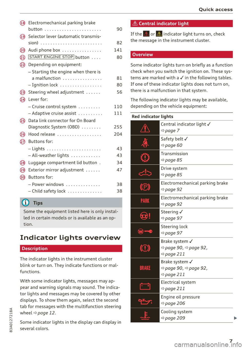
Indicator lights overview
The indicator lights in the instrument cluster
blink or turn on. They indicate functions or mal-
functions.
With some indicator lights, messages may ap-
pear and warning signals may sound. The indica-
tor lights and messages may be covered by other
displays. To show them again, select the second
tab for messages with the multifunction steering
wheel > page 12.
Some indicator lights in the display can display in
several colors.
A\ Central indicator light
If the wa or A indicator light turns on, check
the message in the instrument cluster.
Some indicator lights turn on briefly as a function
check
when you switch the ignition on. These sys-
tems are marked with a V in the following tables.
If one of these indicator lights does not turn on,
there is a malfunction in that system.
The following indicator lights may be available,
depending on the vehicle equipment:
Red indicator lights
Central indicator light ¥
=>page 7
Safety belt
=> page 60
Transmission
=> page 85
Drive system
=> page 85
Electromechanical parking brake
=> page 92
Electromechanical parking brake
=> page 92
Steering ¥
=> page 97
Steering lock
=> page 97
Brake system ¥
=> page 90, > page 92,
=> page 211
Brake system 4
=> page 90, > page 92,
=> page 211
Electrical system
=> page 211
Engine oil pressure
=> page 206
Cooling system
=> page 209
Page 10 of 280
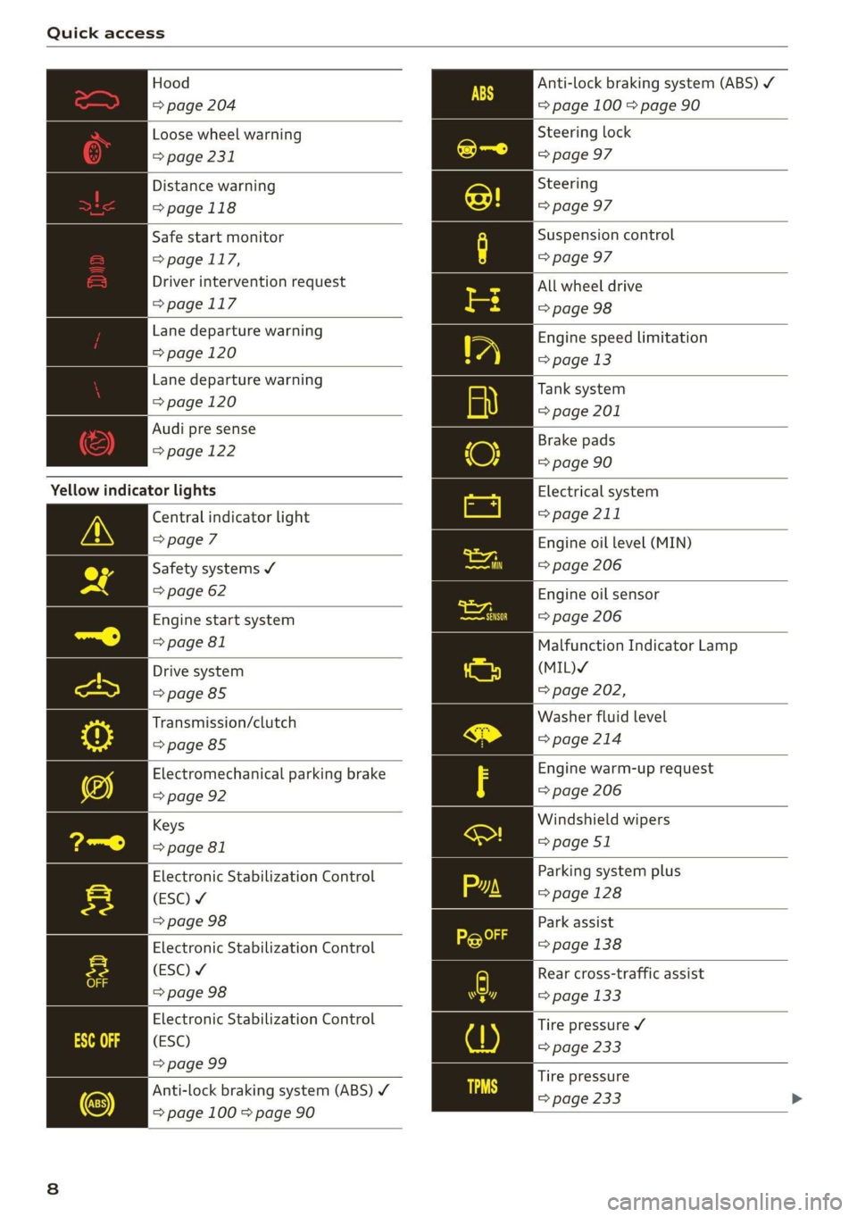
Quick access
Hood
=> page 204
Loose wheel warning
=> page 231
Distance warning
=> page 118
Safe start monitor
= page 117,
Driver intervention request
=>page 117
Lane departure warning
=> page 120
Lane departure warning
=> page 120
Audi pre sense
=> page 122
Yellow indicator lights
Central indicator light
=> page 7
Safety systems ¥
=> page 62
Engine start system
=> page 81
Drive system
=> page 85
Transmission/clutch
=>page 85
Electromechanical parking brake
=> page 92
Keys
=> page 81
Electronic Stabilization Control
(ESC) ¥
=> page 98
Electronic Stabilization Control
(ESC) ¥
=> page 98
Electronic Stabilization Control
(ESC)
=> page 99
Anti-lock braking system (ABS) ¥
=> page 100 > page 90
Anti-lock braking system (ABS) /
= page 100 > page 90
Steering lock
=> page 97
Steering
=> page 97
Suspension control
=> page 97
All wheel drive
=> page 98
Engine speed limitation
=> page 13
Tank system
=> page 201
Brake pads
=> page 90
Electrical system
=> page 211
Engine oil level (MIN)
=> page 206
Engine oil sensor
=> page 206
Malfunction Indicator Lamp
(MIL)Y
=> page 202,
Washer fluid level
=>page 214
Engine warm-up request
=> page 206
Windshield wipers
=> page 51
Parking system plus
=> page 128
Park assist
=> page 138
Rear cross-traffic assist
=> page 133
Tire pressure ¥
=> page 233
Tire pressure
=> page 233
Page 13 of 280
83A012721BA
Instrument cluster
‘ul ant cluster
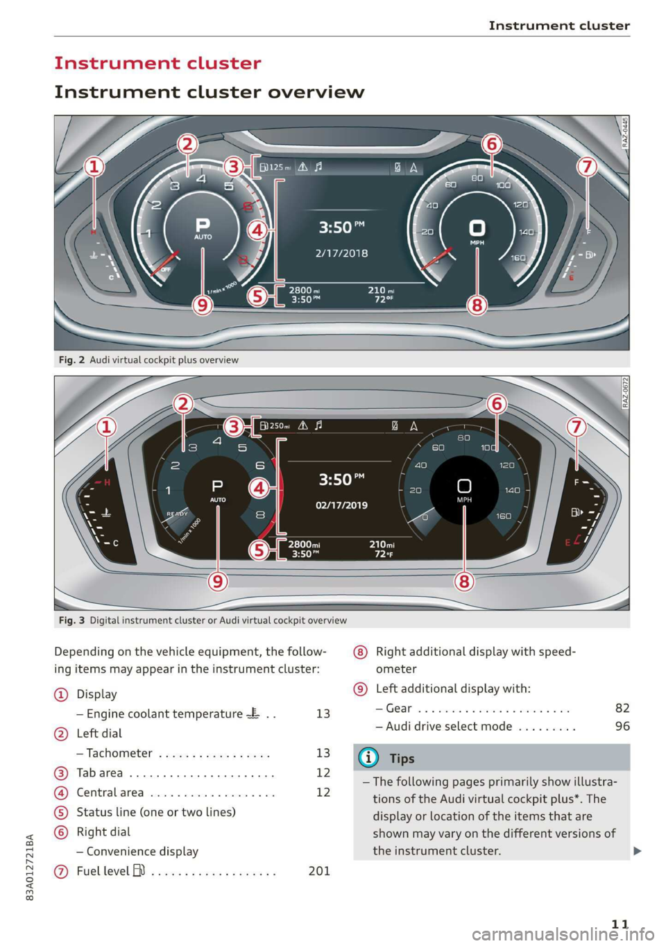
Instrument cluster overview
HO
2/17/2018
3:50™
02/17/2019
Fig. 3 Digital instrument cluster or Audi virtual cockpit overview
Depending on the vehicle equipment, the follow-
ing items may appear in the instrument cluster:
Right additional display with speed-
ometer
(9) Left additional display with:
@) Display
— Engine coolant temperature ~E .. 13 Gear... eee eee eee
5) Left dial — Audi drive select mode .........
D: be’
= Tachometer sss s x sews 2 2 eee 13 @ Tips
ue — The following pages primarily show illustra-
i tions of the Audi virtual cockpit plus*. The
©) Status line (one or two lines) display or location of the items that are
) Right dial shown may vary on the different versions of
— Convenience display the instrument cluster.
@ Fuellevel BD i ects ss cews sc enas es 201
11
>
Page 15 of 280
83A012721BA
Instrument cluster
> Applies to: MMI: Select on the home screen:
SETTINGS > Display & brightness > Virtual
cockpit.
> To adjust the desired layout, press @).
Adjusting the additional display
Applies to: Audi virtual cockpit
Depending on the vehicle equipment, the addi-
tional displays that can be selected may vary.
> Applies to: MMI: Select on the home screen:
SETTINGS > Display & brightness > Virtual
cockpit > (Configure).
> Select the desired additional display.
Reducing the display
Depending on the vehicle equipment, you can
hide the central area in the instrument cluster.
> Select in the instrument cluster: Vehicle func-
tions tab > FE] button > Reduced display, or
> Press the VIEW button on the multifunction
steering wheel.
Coolant temperature
display
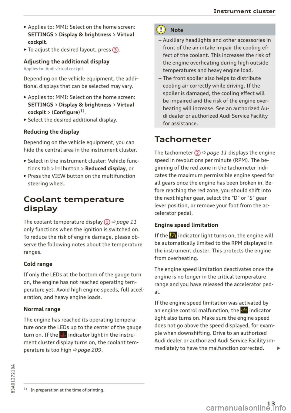
The coolant temperature display @) > page 11
only functions when the ignition is switched on.
To reduce the risk of engine damage, please ob-
serve the following notes about the temperature
ranges.
Cold range
If only the LEDs at the bottom of the gauge turn
on, the engine has not reached operating tem-
perature yet. Avoid high engine speeds, full accel-
eration, and heavy engine loads.
Normal range
The engine has reached its operating tempera-
ture once the LEDs up to the center of the gauge
turn on. If the i | indicator light in the instru-
ment cluster display turns on, the coolant tem-
perature is too high > page 209.
) In preparation at the time of printing.
CG) Note
— Auxiliary headlights and other accessories in
front of the air intake impair the cooling ef-
fect of the coolant. This increases the risk of
the engine overheating during high outside
temperatures and heavy engine load.
—The front spoiler also helps to distribute
cooling air correctly while driving. If the
spoiler is damaged, the cooling effect will
be impaired and the risk of the engine over-
heating will increase. See an authorized Au-
di dealer or authorized Audi Service Facility
for assistance.
Tachometer
The tachometer 2) > page 11 displays the engine
speed in revolutions per minute (RPM). The be-
ginning of the red zone in the tachometer indi-
cates the maximum permissible engine speed for
all gears once the engine has been broken in. Be-
fore reaching the red zone, you should shift into
the next higher gear, select the "D" or "S" gear
lever position, or remove your foot from the ac-
celerator pedal.
Engine speed limitation
If the Ay indicator light turns on, the engine will
be automatically limited to the RPM displayed in
the instrument cluster. This protects the engine
from overheating.
The engine speed limitation deactivates once the
engine is no longer in the critical temperature
range and you have released the accelerator ped-
al.
If the engine speed limitation was activated by
an engine control malfunction, the By indicator
light also turns on. Make sure the engine speed
does not go above the speed displayed, for exam-
ple when downshifting. Drive to an authorized
Audi dealer or authorized Audi Service Facility im-
mediately to have the malfunction corrected.
13
>
Page 16 of 280
Instrument cluster
@) Note
The tachometer needle should only be in the
red zone briefly: Otherwise, this increases the
risk of engine damage. The location where the
red zone begins varies depending on the en-
gine.
Odometer
The trip odometer and odometer are displayed in
the status line ©) > page 11.
The trip odometer shows the distance driven
since it was last reset. It can be used to measure
short distances. The odometer shows the total
distance that the vehicle has been driven.
Resetting the trip odometer
> Select in the instrument cluster: Vehicle func-
tions tab > [=] button > Reset mi.
@) Tips
Distances are displayed in mi (miles) or km
(kilometers).
Outside temperature
display
The outside temperature is displayed in the sta-
tus line @) > page 11.
If your vehicle is stationary or if you are driving at
very low speeds, the temperature displayed in
the instrument cluster may be slightly higher
than the actual temperature outside due to heat
radiating from the engine.
At temperatures below 41 °F (+5 °C), a snowflake
symbol appears in front of the temperature dis-
play > A.
ZA\ WARNING
Do not assume the roads are free of ice based
on the outside temperature display. Be aware
that there may be ice on roads even when the
outside temperature is around 41 °F (+5 °C)
and that ice can increase the risk of accidents.
14
Vehicle functions
The trip computer is displayed in the first tab of
the driver information system. Additional vehicle
functions can be accessed depending on the vehi-
cle equipment.
> Press the =] button on the multifunction steer-
ing wheel.
— On-board computer > page 14
— Reduced display > page 13
— Reset trip odometer > page 14
On-board computer
Resetting values to zero
Requirement: the Consumption, Short-term
memory, or Long-term memory display must be
selected.
> To reset the values in one of the memories to
zero, press and hold the left thumbwheel on
the multifunction steering wheel for one sec-
ond, or
> Select in the instrument cluster: Vehicle func-
tions tab > [=] button > Reset mi.
Depending on the vehicle equipment, you can call
up the following displays in the on-board com-
puter one at a time by turning the left thumb-
wheel on the multifunction steering wheel:
— Time and date > page 195
— Average consumption > page 15
— Short-term memory overview
— Long-term memory overview
— Energy consumers > page 15
— Driver assistance
Short-term memory and long-term memory
The short-term memory collects driving informa-
tion from the time the ignition is switched on un-
tilit is switched off. If you continue driving within
two hours after switching the ignition off, the
new values will be included when calculating the
current trip information.
Page 79 of 280
83A012721BA
Warm and cold
Warm and cold
Climate control system
Your vehicle has a deluxe automatic climate con-
trol system with two zones where the tempera-
ture and air distribution can be adjusted sepa-
rately on the left and right front sides.
The climate control system warms, cools, dehu-
midifies, and filters the incoming air. It is the
most effective when the windows and panoramic
glass roof are closed. If there is a build-up of
heat inside the vehicle, ventilation can help to
speed up the cooling process.
In all heating mode functions except defrost, the
blower only switches to a higher speed once the
engine coolant has reached a certain tempera-
ture.
Pollutant filter
The pollutant filter removes pollutants such as
dust and pollen from the air.
ZA WARNING
— You should not use the recirculation mode
for an extended period of time, because no
fresh air is drawn in and the windows can
fog when cooling mode is switched off. This
increases the risk of an accident.
— Individuals with reduced sensitivity to pain
or temperature could develop burns when
using the seat heating function. To reduce
the risk of injury, these individuals should
not use seat heating.
() Note
To reduce the risk of damage to the seat heat-
ing elements, do not kneel on the seats or
place heavy pressure on one area of the seat.
(@) For the sake of the environment
Energy can be saved by switching off the A/C
mode.
@ Tips
—To prevent interference with the heating
and cooling output and to prevent the win-
dows from fogging over, the air intake in
front of the windshield must be free of ice,
snow, and leaves.
— Condensation from the cooling system can
drip and form a puddle of water under the
vehicle. This is normal and does not mean
there is a leak.
— The energy management system may tem-
porarily switch off certain functions, such as
the seat heating* or rear window defogger.
These systems are available again as soon as
the energy supply has been restored.
— If the front passenger's seat heating is
turned on, it will not turn on again automat-
ically if more than 10 minutes have passed
between switching the ignition off and
switching it on again.
77
Page 81 of 280
83A012721BA
Warm and cold
The air vents are adjustable > page 79.
Air vents are located under the front seats and on
the end of the center console to heat the rear of
the vehicle. You can adjust the amount of air and
the air distribution using the thumbwheels.
& Defrosting
The windshield and side windows are defrosted
or cleared of condensation as quickly as possible.
The maximum amount of air flows mainly from
the vents below the windshield. Recirculation
mode switches off. The temperature should be
set at +72°F (22°C) or higher. The temperature is
controlled automatically. In the § setting, the
A/C cooling mode switches on automatically, de-
pending on the outside air temperature.
The AUTO button switches the defroster off.
<= Recirculation mode
In recirculation mode, the air inside the vehicle is
circulated and filtered. This prevents the unfil-
tered air outside the vehicle from entering the
vehicle interior. The recirculation mode can be
turned on manually or automatically”.
Switching recirculation mode on and off: Press
the <> button.
Automatic recirculation mode®*: The air quality
sensor that is designed for diesel and gasoline
exhaust automatically switches the recirculation
mode on or off depending on the level of pollu-
tants in the outside air. Auto recirculation can be
switched on or off.
Applies to: MMI: Select on the home screen: Ve-
hicle > Climate control > Auto recirculation.
You can press either the <, AUTO or §% button
to switch recirculation mode off.
@ Rear window defogger
The rear window defogger only operates when
the engine is running. It switches off automati-
cally after approximately 10 to 20 minutes, de-
pending on the outside temperature.
To prevent the rear window defogger from
switching off automatically, press and hold the
® button for more than two seconds. This re-
mains stored up to approximately 15 minutes af-
ter turning off the ignition.
a Seat heating*
The seat heating temperature can be set at mul-
tiple levels. Press af once to switch on the highest
level. Press af again to decrease the heat output
one level at a time. The seat heating is off when
the LED in the button is off.
Adjusting the vents
You can open or close the center and rear vents in
the cockpit as well as the vents in the rear center
console using the thumbwheels. The levers ad-
just the direction of the airflow from the vents.
Steering wheel heating
Sy ieee Keli
Applies to: vehicles with steering wheel heating
> Press the @ © page 26, fig. 19 button on the
multifunction steering wheel to switch the
steering wheel heating on and off.
@) Tips
The steering wheel heating settings are stor-
ed automatically and assigned to the vehicle
key that is in use.
Te
Applies to: vehicles with steering wheel heating
@& Steering wheel heating: on / Steering wheel
heating: off
This message appears if you switched the steer-
ing wheel heating on or off by pressing the but-
ton on the multifunction steering wheel.
79
Page 82 of 280
Driving
Driving
Starting the vehicle
eta
Applies to: vehicles with convenience key
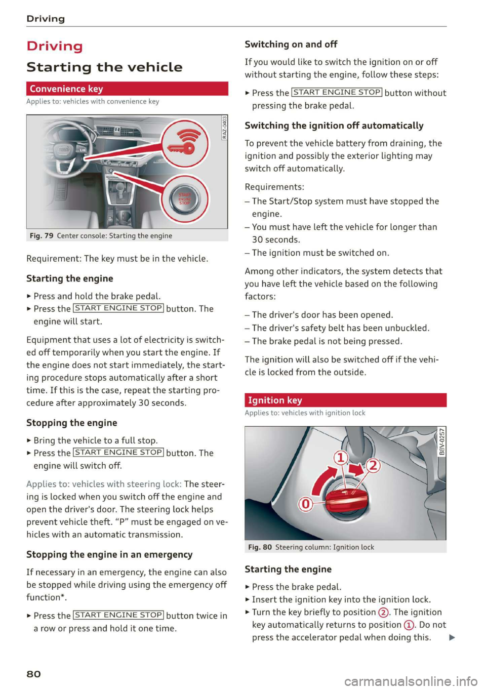
Fig. 79 Center console: Starting the engine
Requirement: The key must be in the vehicle.
Starting the engine
> Press and hold the brake pedal.
> Press the [START ENGINE STOP.
engine will start.
button. The
Equipment that uses a lot of electricity is switch-
ed off temporarily when you start the engine. If
the engine does not start immediately, the start-
ing procedure stops automatically after a short
time. If this is the case, repeat the starting pro-
cedure after approximately 30 seconds.
Stopping the engine
> Bring the vehicle to a full stop.
> Press the [START ENGINE STOP
engine will switch off.
button. The
Applies to: vehicles with steering lock: The steer-
ing is locked when you switch off the engine and
open the driver's door. The steering lock helps
prevent vehicle theft. “P” must be engaged on ve-
hicles with an automatic transmission.
Stopping the engine in an emergency
If necessary in an emergency, the engine can also
be stopped while driving using the emergency off
function*.
START ENGINE STOP > Press the button twice in
a row or press and hold it one time.
80
Switching on and off
If you would like to switch the ignition on or off
without starting the engine, follow these steps:
START ENGINE STOP > Press the button without
pressing the brake pedal.
Switching the ignition off automatically
To prevent the vehicle battery from draining, the
ignition and possibly the exterior lighting may
switch off automatically.
Requirements:
— The Start/Stop system must have stopped the
engine.
— You must have left the vehicle for longer than
30 seconds.
— The ignition must be switched on.
Among other indicators, the system detects that
you have left the vehicle based on the following
factors:
— The driver's door has been opened.
— The driver's safety belt has been unbuckled.
— The brake pedal is not being pressed.
The ignition will also be switched off if the vehi-
cle is locked from the outside.
eT
Applies to: vehicles with ignition lock
ny 6 a =
> @ oO
Fig. 80 Steering column: Ignition lock
Starting the engine
» Press the brake pedal.
> Insert the ignition key into the ignition lock.
> Turn the key briefly to position @). The ignition
key automatically returns to position @. Do not
press the accelerator pedal when doing this. >